

Digiop Black BLK-IPS101 Quick Installation Manual
H.264 Network IP Camera
Attach peripheral devices to t he terminal blocks as neede d. For detailed interface sp ecications, refer to the
user manual.
Quick Installation Guide
This document guides you through the basic steps to ins tall and congure your Digiop® Black BLK-IPS101 IP
camera. For detailed instr uctions, refer to the User Manual.
Find the camera’s MAC address on the pro duct label and enter it here: __ ___ ___ ____ ___ ___
Step 1. Install the camera
Install the camera mounting bracket using the instructions provided with the bracket .
Attach the adapter for mounting the camera to side with the label or to the opposite side with the four
screws provided.
Mounting
adapter
Remove the protec tive cap covering the camera CCD.
Attach the lens assembly to the cam era by screwing it clockwis e onto the camera until it is fully seate d. The
lens may require a mounting ring adapter to t onto t he camera.
Step 2. Connect the camera to the LAN
Attach the network L AN cable to the Ethernet connec tor on the camera backpanel.
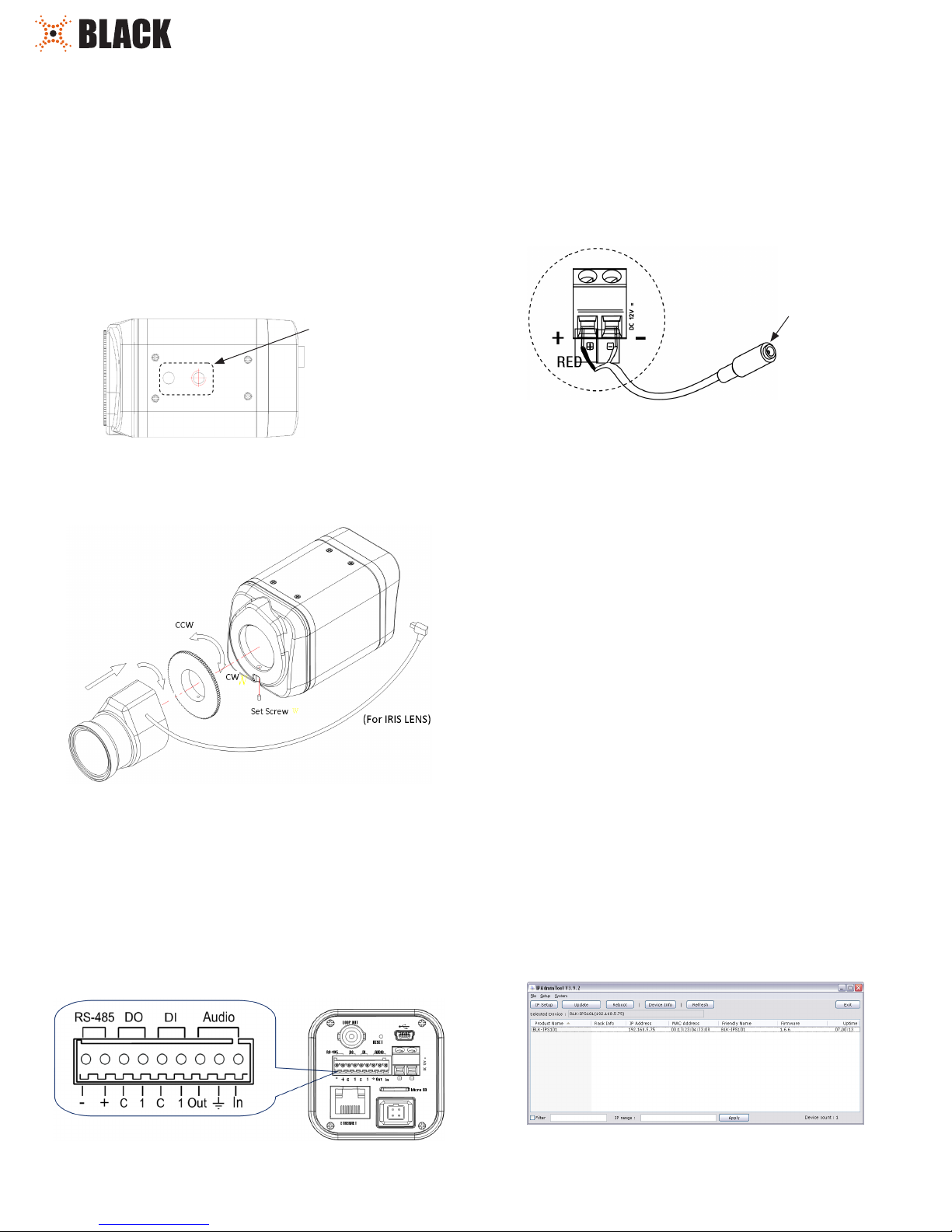
Your camera can be powered locally with a 12 V DC adapter, or across the LAN (PoE). If using the power
adapter, attach the DC jack adapter cable to the DC 12V power adapter terminals on the back of the camera.
Connect the red wire of the adapter c able to the + terminal, and the black (or white) wire to the - terminal.
DO NOT apply power to the camera at t his time.
DC Jack
Adapter
Cable
Step 3. Install IPAdmin Tool
The IPAdminTool is a u tility for conguring the network settings of your Digiop Black camer as and installing
new rmware. It can be loaded on a Micro soft Windows XP, Vista or Windows 7 operating system. At a
computer on the sam e LAN (subnet) where your cameras will be installed, do the f ollowing:
1. Insert the CD mini disk provided w ith your camera into your computer’s CD ROM drive and open the
CD in a Windows Explorer window.
Tighten the lens set screw with the hex wrench prov ided.
If the lens assembly has an Auto Iris feature, attach the lens cable to the 4 -pin connector on the back of the
camera.
Attach the camera to the mounting bracket.
CONNECTIONS
Connections to the camera for audio in and out (microphone and speaker), D/I sensor, alarm, and RS-4 85
control are made through the 9-pin ter minal block. Plug the terminal block into the mating connec tor on
the camera.
2. Find the IPAdminTool directory on the CD.
3. Copy the IPAdminTool directory with its contents to your computer hard drive.
Step 4. Configure the network settings of you camera
When your IP camera is attached to a network and initially powered o n, it at tempts acquire compatible
network s ettings from a DHCP ser ver. If it cannot nd a DHCP ser ver, it congure s itself with the following
static (xed) settings, which may or may not be compatible with other devices on the net work.
IP address: 192.168.0.100
Subnet mask: 255.255.255.0
Gateway: 192.168.0.1
Your camera must be congured with static network sett ings that are compatible with the LAN. If your
LAN has a DHCP ser ver, use the following sub-step. Other wise, use the sub-step pro cedure below for LANs
without DHCP.
Installing cameras on LANs with DHCP
1. Connect your c amera to the LAN, then power on the camera.
2. Open the IPAdminTool directory on your computer, then double click t he le IPAdminTool.exe to
start the application. When the IPAdmin Tool starts, it will discover all the IP devices it suppor ts that
exist on the network . The discovery process may take a few minutes.
1
www.digiop.com
BLK-IPS101_CQ
5/27/11
Review the list of IP devices found by IPAdmin Tool. You can identify your camera by the MAC
address. If the c amera was not found, click the Refresh but ton every minute until your camera
appears in the lis t.
3. After nding your camera, right clic k the entry, then select IP Address from t he drop-down list. An
IP Setup window will open.
Static Option
4. In the IP Setup window, click the Static option bullet. If you have other compatible net work
settings you want to apply to the device, enter them in the appropriate locations. Click Setup to
save settings.
d. Record the IP Address, Subnet Mask, and Default Gateway f or your PC’s Ether net adapter for
future ref erence.
NOTE
The Ethernet adapter data you see by using ipcong will probably be d ierent from tha t shown
in the example above. If you are using Windows Vista or Windows 7, the IP address is identied
as the “IPv4 Address.”
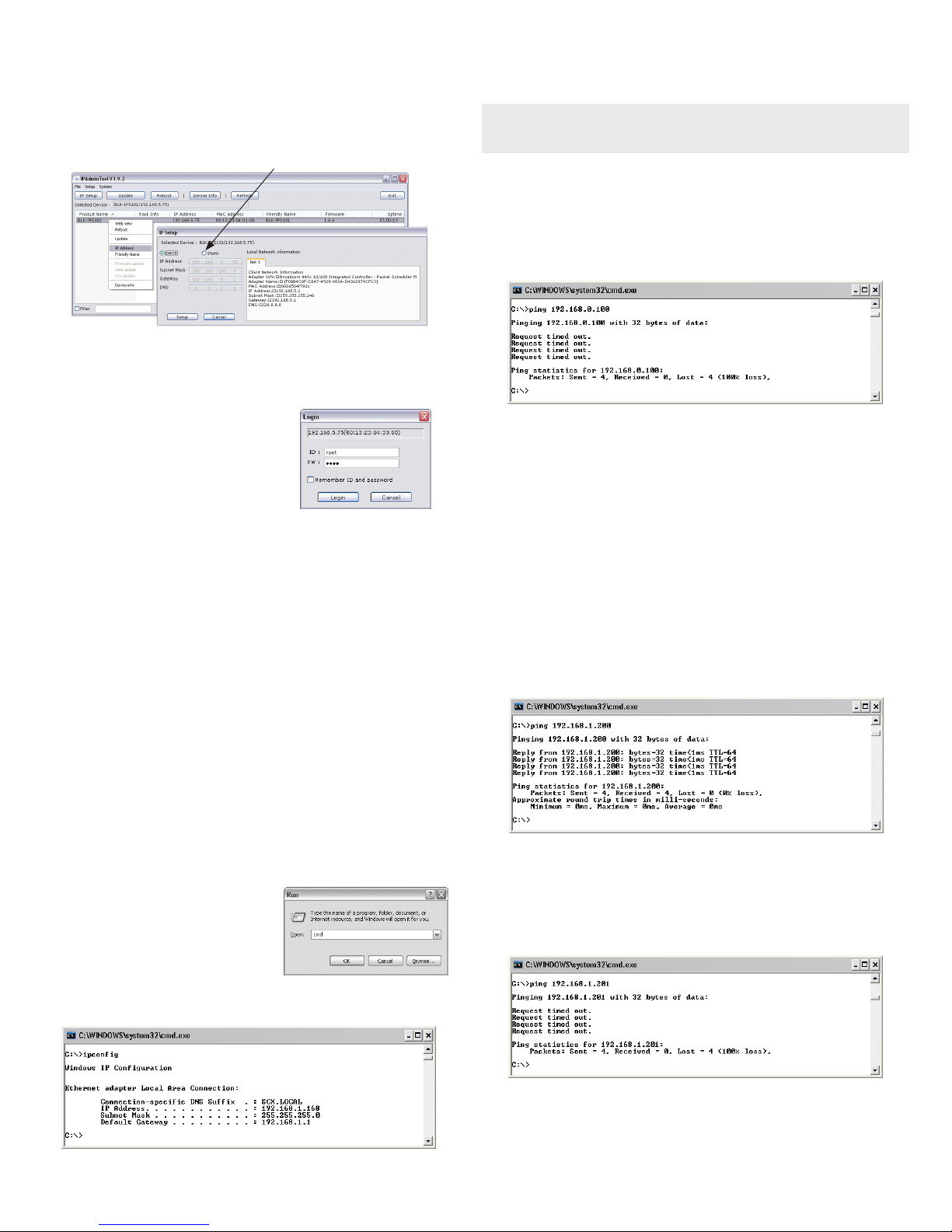
Check LAN for defa ult IP address compatibi lity
Before conne cting your camera to the LAN, check the net work to see if IP address 192.168.0.100 is already
in use. At a Microsof t Windows computer attached to the LAN where the camera will be connecte d, open a
Command Prompt window and enter:
ping 192.168.0.100
5. In the Login window, enter the ID and PW
(password) for your camera, then click Login. The
default adminis trator values for the ID and PW are
root and pass.
6. In the IPAdmin Tool window, click Refresh. Verif y that the entry representing the camera now
shows the (new) static IP address.
7. Continue with procedure Step 5. Setup c amera Basic Conguration.
Installing cameras on LANs without DHCP
In network s without a DHCP server, cameras must be powere d on and recongured one at a time to avoid
addressing conic ts between other cameras, or possibly with another device on the net work. Conguring
the networ k settings of your cameras includes these steps:
— Determine t he network settings of your computer.
— Check the network for compatibilit y with the default static network s ettings of your camera.
— Find an IP address that is not in use and c an be assigned to your camera.
— Attach your camera to the net work, power it on, and conguring i t with new network
settings.
Determine t he network settings o f your computer
1. At a PC attached to the LAN where your camera will be connected, determine the IP addre ss, subnet
mask, and default gateway of your PC. To nd this information:
a. Hold down the Windows key and press r to
open the Run dialog box.
b. Type cmd in the entr y eld, then click OK to
open the Command Prompt window.
The “Reques t timed out” response indicates that the IP address is not in use and the camera can be
connected without causing conict s. If the response from the ping command received a “Reply..”, the IP
address is in use. Contact Technical Supp ort for further assistance, if ne eded.
Find network se ttings (IP addresses) that are n ot in use
1. At your PC, nd an IP address on your network that is not in use:
a. Write down the EXACT IP address of your PC up to the third/last period. Using the e xample
shown above, this ex pression is: 192.168.1. Af ter the third period, include any number
between 1 an d 254 that is dierent from the one in your PC’s IP address, 168. As a r st try,
let’s choose 20 0, which will form the IP addre ss 192.168.1.200.
b. Next, use the ping command in the Command Prompt window to see if this IP address is in
use on your net work. Enter:
ping 192.168.1.200.
In the example shown above, the message “Reply f rom 192.168.1.200: ..” indicates that
your PC can reach a device with that IP addre ss, and that address is in use (i.e., you cannot
use it for your camera).
c. Since the ping tes t showed that 192.168.1.200 is in use, try another number bet ween 1 and
254. Let’s try to ping 192.168.1.201. At the command prompt, enter: ping 192.168.1.201
c. At the command prompt, enter ipcong. The response will show the your PC’s network
settings.
2
www.digiop.com
d. In this test, the message “Request timed out” indicates that your PC cannot reach the
device with that IP address, and that address is probably not in use. If this test showed that
this IP address is in use, try other IP addresses u sing the steps above until an unused address
is found.
© 2011 DIGIOP, Inc. All rights reserved.
 Loading...