

Digiop Black BLK-IPE4101 Quick Installation Manual

4-Channel H.264
Network Video Encoder
Quick Installation Guide
This document guides you through the basic steps to ins tall and congure your DDIGIOP™ Black
BLK-IPE4101 4-channel IP encoder. For detaile d instructions, refer to the User Manual.
Find the four MAC ad dress on the product label and enter them here: _ _____ _____ ___ ____.
__ _____ _____ _____ _. ___ ____ ___ ___ ____ _. ___ ___ _____ _____ __.
Step 1. Install the encoder
Mount the encoder in a s ecure location using the hardware installation kit provided. The kit includes
mounting brackets that slide into the sides of the encoder.
Connect video feeds f rom four analog cameras to the four Vin BNC connec tor (Vin1, Vin2, Vin3, Vin4) on the
front of the encoder.
1. Insert the CD disk provided with your encoder into your computer’s CD ROM drive and open the CD in
a Windows Ex plorer window.
2. Find the IPAdminTool directory on the CD.
3. Copy the IPAdminTool directory with its contents to your computer hard drive.
Step 4. Configure the network settings of you encoder
When your IP encoder is at tached to a network and ini tially powered on, it attempts acquire compatible
network s ettings for each IP channel from a DHCP ser ver. If it cannot nd a DHCP server, it congures each
channel with the f ollowing static (xed) sett ings:
IP address: 192.168.0.100
Subnet mask: 255.255.255.0
Gateway: 192.168.0.1
Your encoder must be congure d with static network settings that are compatible with the LAN. If your
LAN has a DHCP ser ver, use the following sub-s tep. Otherwise, use the sub -step procedure below for LANs
without DHCP.
Installing encoders on LANs with DHCP
1. Connect your encoder to the LAN, then plug in the power adapter to power it on.
2. Open the direc tory IPAdminTool directory on your computer, then double click the le
IPAdminTool.exe to start the application. When IPAdmin Tool star ts, it will discover all the IP
devices it supports that exist on the network. The discover y process may take a few minutes.
Connections to the encoder for audio in and out (microphone and speaker), D/I sensor, alarm, video out
BNC, RS-232C, and RS- 485 control are made through two 6-pin and two 8-pin terminal blocks. Vin1 is
associated with Ain1 (microphone), Aout1 (speaker), DI1 (sensor), DO1 (alarm output), and the rs t IP
channel. Similarily, Vin2 is associated with Ain2, Aout 2, etc. Attach peripheral devices to the terminal
blocks as shown below. For detailed interface specications, refer to the us er manual.
Ain
Ain
Grounds
1 - 4 DI 1 - 4 RS-232 TX, RX, Gnd
Aout
1 - 4
Grounds
Ground
DO 1 - 4Aout
RS-485 +, –, Gnd
Common
Step 2. Connect the encoder to the LAN
Attach a net work LAN cable to the RJ-45 connector on the encoder backpanel.
Attach the DC12V adapter to the power connector on the encoder. DO NOT apply p ower to the encoder
at this time.
Step 3. Install IPAdmin Tool
Check the list of devices found by IPAdmin Tool. You can identif y your encoder IP channels by their
MAC addresses.
The Rack Info eld “M” number is directly associate d with the Vin channel (M0 for Vin1, M1 for Vin2,
etc.). The Rack Info identiers in the list may not appear in order. See the following table for t he
example shown above.
Rack Inf o Vin Chan nel IP Add ress (via DHCP) MAC Addre ss
R0, B0, M0 Vin1 192.168.5.43: 00:13:23:D4:D1:45
R0, B0, M1 Vin2 192.168.5.59 00:13:23:D4:D1:46
R0, B0, M2 Vin3 192.168.5.61 00:13:23:D4:D1:47
R0, B0, M3 Vin4 192.168.5.50 00:13:23:D4:D1:48
If an encoder channel was not found, click the Refresh button ever y minute until the four channels
for your encoder app ear in the list.
3. Right click your encoder entry with Rack Info R0, B0,M0 (IP channel associated with Vin1), then
select IP Address from the drop- down list. An IP Setup window will open.
Static Option
The IPAdminTool is a utility for conguring the net work settings of your DIGIOP™ Black encoders and
installing new rmware. It can be loade d on a Microsoft® Windows® XP, Vista or Windows 7 operating
system. At a computer on the same LAN (subnet) where your encoder will be installe d, do the following:
1
www.digiop.com
BLK-IPE4101_PQ
8/1/11
4. In the IP Setup window, click the Static option bullet. If you have other compatible network settings
you want to apply to the dev ice, enter them in the appropriate loc ations. Click Setup to continue.
5. In the Login window, enter the ID and PW
(password) for your encoder, then click Log in. The
default adminis trator values for the ID and PW are
root and pass.
6. In the IPAdmin Tool window, click Refresh. Verif y that the entry representing the encoder now
shows the (new) static IP address.
7. Repeat these s teps to setup the other three encoder IP channels.
8. Continue with procedure Step 5. Setup encoder Basic Conguration.
Find network se ttings (IP addresses) that are n ot in use
1. At your PC, nd an IP address on your network that is not in use:
a. Write down the EXACT IP address of your PC up to the third/last period. Using the e xample
shown above, this ex pression is: 192.168.5. After the third period, include any numb er
between 1 an d 254 that is dierent from the one in your PC’s IP address, 3. As a rst try, let’s
choose 75, which will form the IP address 192.168.5.75.
b. Next, use the ping command in the Command Prompt window to see if this IP address is in
use on your net work. Enter: ping 192.168.5.75.
Installing encoders on LANs without DHCP
Conguring the network settings of your encoders includes these steps:
— Determine t he network settings of your computer.
— Check the network for compatibilit y with the default static network s ettings of your encoder.
— Find four network settings (IP addresses) that are not in us e and can be assigned to the IP
channels of your encoder.
— Attach the encoder to the net work, power it on, and congure each IP channel with new
network s ettings.
Determine t he network settings o f your computer
1. At a PC attached to the LAN where your encoder will be connected, deter mine the IP address, subnet
mask, and default gateway of your PC. To nd this information:
a. Hold down the Windows key and press r to
open the Run dialog box.
b. Type cmd in the entr y eld, then click OK to
open the Command Prompt window.
c. At the command prompt, enter ipcong. The response will show the your PC’s network
settings.
d. Record the IP Address, Subnet Mask, and Default Gateway f or your PC’s Etherne t adapter for
reference later.
NOTE
If you are using Windows Vista or Windows 7, the IP address is identied as the “IPv4 Address.”
Check the LAN for de fault IP address compati bility
In the example shown above, the message “Reply f rom 192.168.5.75: ..” indicates that
your PC can reach a device with that IP addre ss, and that address is in use (i.e., you cannot
use it for your enco der).
c. Since the ping tes t showed that 192.168.5.75 is in use, try another number b etween 1 and
254. Let’s try to ping 192.168.5.20. At the command prompt, enter: ping 192.168.5.20
d. In this test, the message “Request timed out” indicates that your PC cannot reach the
device with that IP address, and that address is probably not in use. If this test showed that
this IP address is in use, try other IP addresses u sing the steps above until an unused address
is found.
e. Repeat the se steps to nd IP addresses for the other IP channels of your encoder.
Attach your e ncoder to the network, power i t on, and conguring it wi th new network setting s
1. Connect the encoder to the LAN, then plug in the power adapter to power it on. Wait until the
initialization process complete s (about 4 minute s) before cont inuing.
2. Open the direc tory IPAdminTool directory on your computer, then double click the le
IPAdminTool.exe to start the application. When the IPAdmin Tool starts, it will discover all the IP
devices it supports that exist on the network. The discover y process may take a few minutes.
3. In the Product list, nd the entries with the MAC addresses of t he encoder you installed. If all four IP
addresses are not shown, click Refresh once a minute until all four addresses are shown.
4. Right click the encoder entry with Rack Info R0,B0,M0 (IP channel associated with Vin1), then
select IP Address.
Static Option
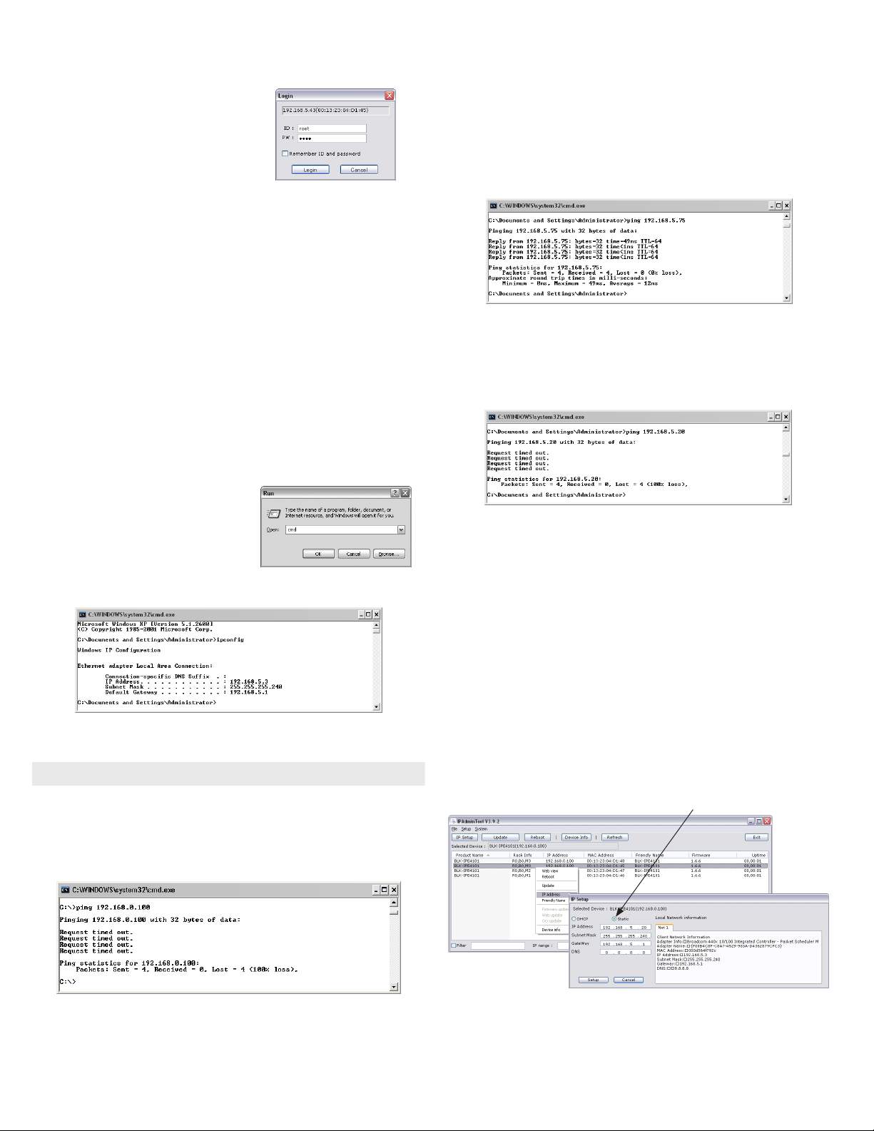
Before conne cting your encoder to the LAN, che ck the network to see if IP address 192.168.0.100 is already
in use. At a Microsof t Windows computer attached to the LAN where the encoder will be connected, open
a Command Prompt window and enter: ping 192.168.0.100
The “Reques t timed out” response indicates that the IP address is not in use and the encoder can be
connected without causing conict s. If the response from the ping command received a “Reply..”, the IP
address is in use. Contact Technical Supp ort for further assistance, if ne eded.
2
www.digiop.com
5. In the IP Setup window:
a. Selec t the Static option if it is not selected.
b. Enter the new IP addres s for your encoder into the IP Address eld.
c. Enter the subnet mask of your computer into the Subnet Mask eld.
© 2011 DIGIOP, Inc. All rights reserved.
 Loading...