

Page 1
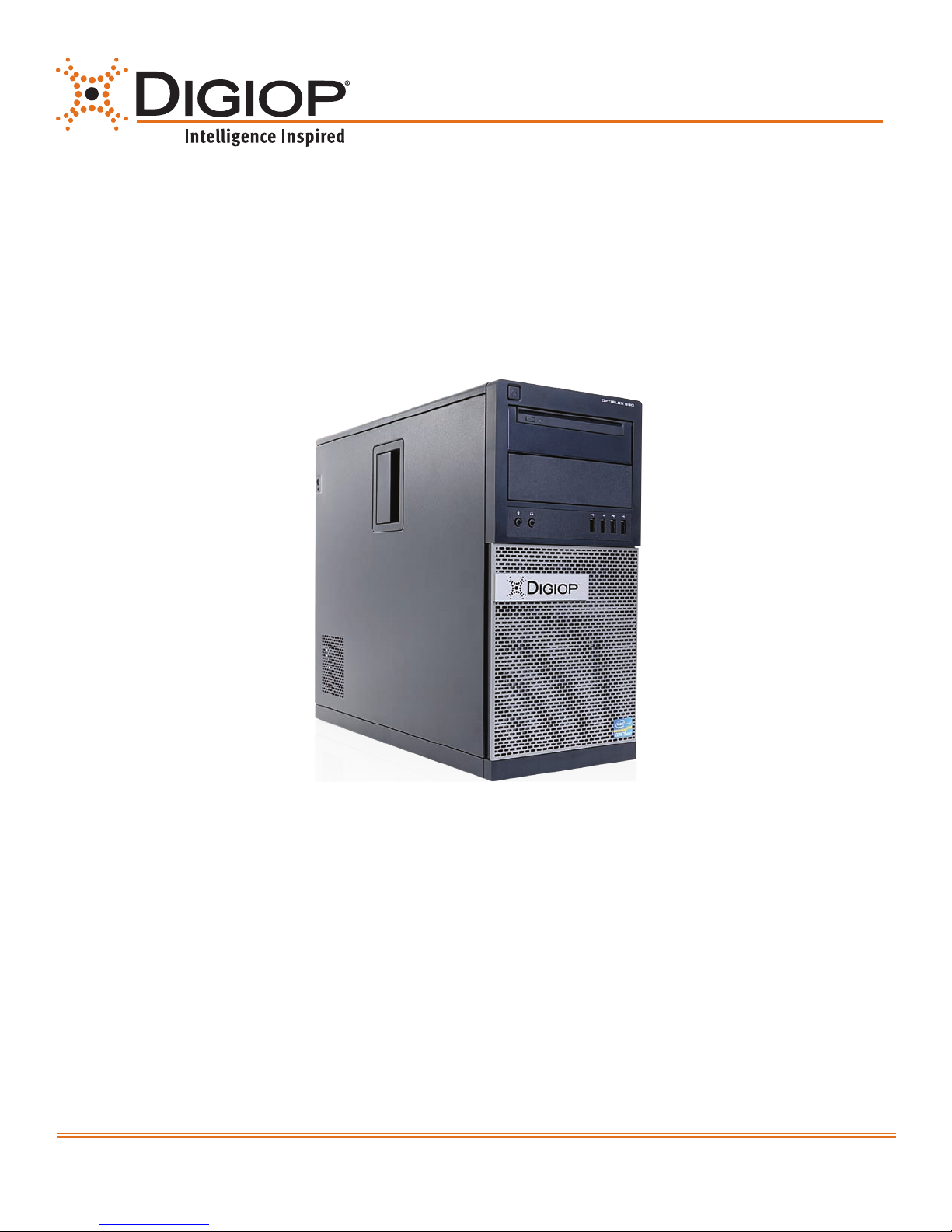
DIGIOP® 990 Chassis
Hardware Quick Start Guide
Video and Data Management System
DIGIOP® 990 Chassis for AH, AI, PH Series Systems
Congratulations on your new DIGIOP® Video and Data Management System.
This guide provides setup instructions for your server hardware.
For more information, visit www.digiop.com
www.digiop.com
1
DO_Opti990-H4_CoQ
1/14/13
Page 2

1. Getting Started
Unpacking the Contents
The following are included with your system. Please inspect
these and the other system components while unpacking.
• Quick Start Guide
• Surge Protection Notice
• Recovery DVDs
• Application DVD
• Mouse/Keyboard
• Power Cord
• Video Input Cable(s) (AH, PH Series only)
• Audio Input Cables (AH Series only)
• PTZ Control Cable (AH Series only)
• RS232 PTZ Control Cable
• I/O Connector (PH Series only)
Choose a Proper Location
Select a location for the system that meets the following
requirements.
Notice: Excessive heat can shorten the life of electronics.
• Adequate ventilation to avoid excessive heat (climate
controlled environment)
• Uninterrupted Power Supply (UPS)
• Moisture-free environment
• A place away from direct sunlight
• An area with minimal dust or debris
Site Installation
Hardware Setup – Connect all input devices and external peripherals to the system. Please refer to the diagrams in regard to
what should be connected to your system.
• Indoor & Outdoor Camera(s)
• VGA/DVI monitor
• Spot Out Monitor
• PTZ Camera(s) - Optional
• Audio in
• Speakers - Optional
Notice: When installing indoor and outdoor cameras, an in-line surge suppressor or equivalent should be used to reduce
exposure to surges and lightning strikes.
2
www.digiop.com
• Ethernet
• Mouse
• Keyboard
• Relays and I/O
• Cash Register (RS232) - Optional
• Power Cord
Page 3
2. About Your System
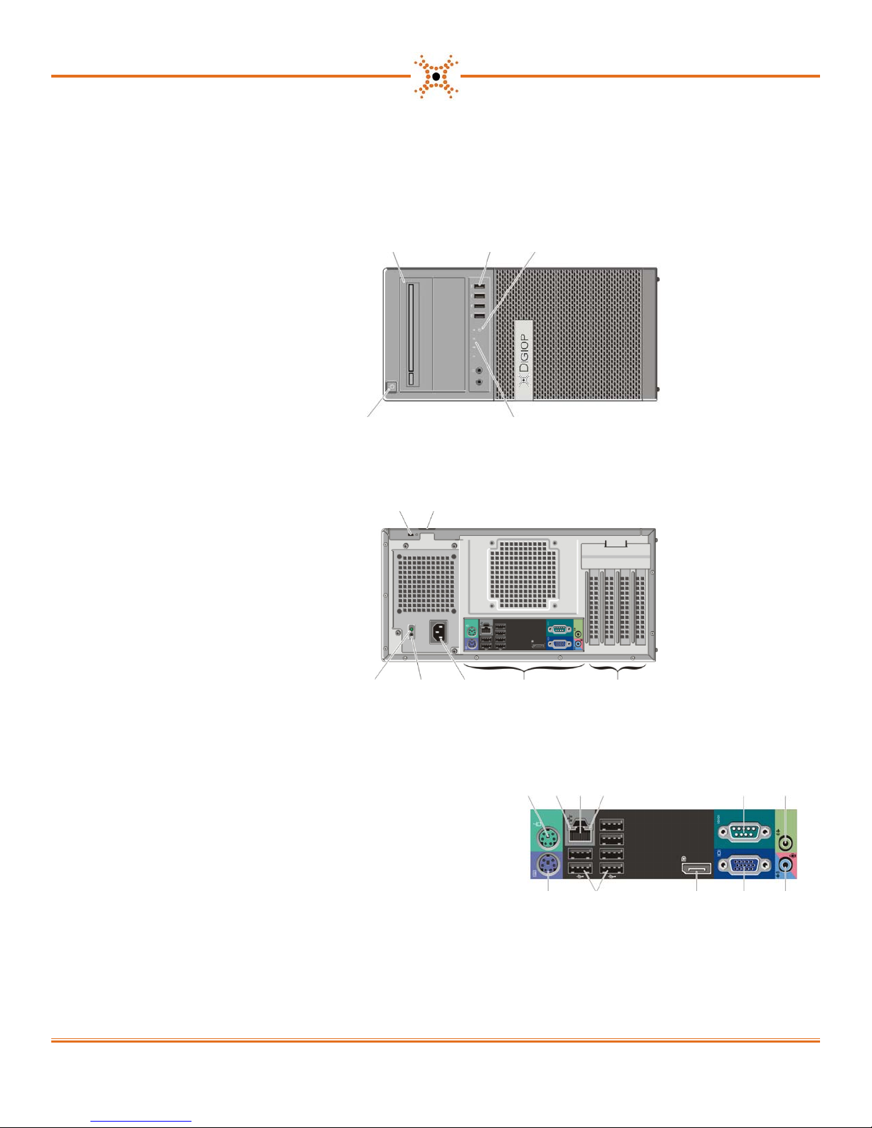
Front View
1. Slot load optical drive and eject button
2. USB 2.0 connectors (4)
3. Drive activity light
4. Diagnostic lights
5. Power button, power light
Back View
21 3
45
1. Security-cable slot
2. Padlock ring
3. Expansion-card slots
4. Back panel connectors
5. Power cable connector
6. Power supply self test button
7. Power supply diagnostic light
Back Panel Connectors
1. PS/2 Mouse connector
2. Link integrity light
3. Network connector
4. Network activity light
5. Serial connector
6. Line-out connector
21
7. Line-in (not used)
8. VGA connector
9. DisplayPort connector
10. USB 2.0 connectors (6)
11. PS/2 Keyboard connector
3457 6
21
3 4 5
6
91011
7
8
*NOTICE: Using the DisplayPort for video may require an optional adapter to connect to older monitors which only support VGA and/or DVI
(available at www.dell.com).
When connecting to a DisplayPort monitor or adapter, multi-monitor capability of the system is not be available during boot or when running DOS.
Output will be limited to the DisplayPort monitor only. When the system is booted to Windows and the graphics driver is loaded, multi-monitor support will
be fully functional.
www.digiop.com
3
Page 4
3. Setting Up Your System
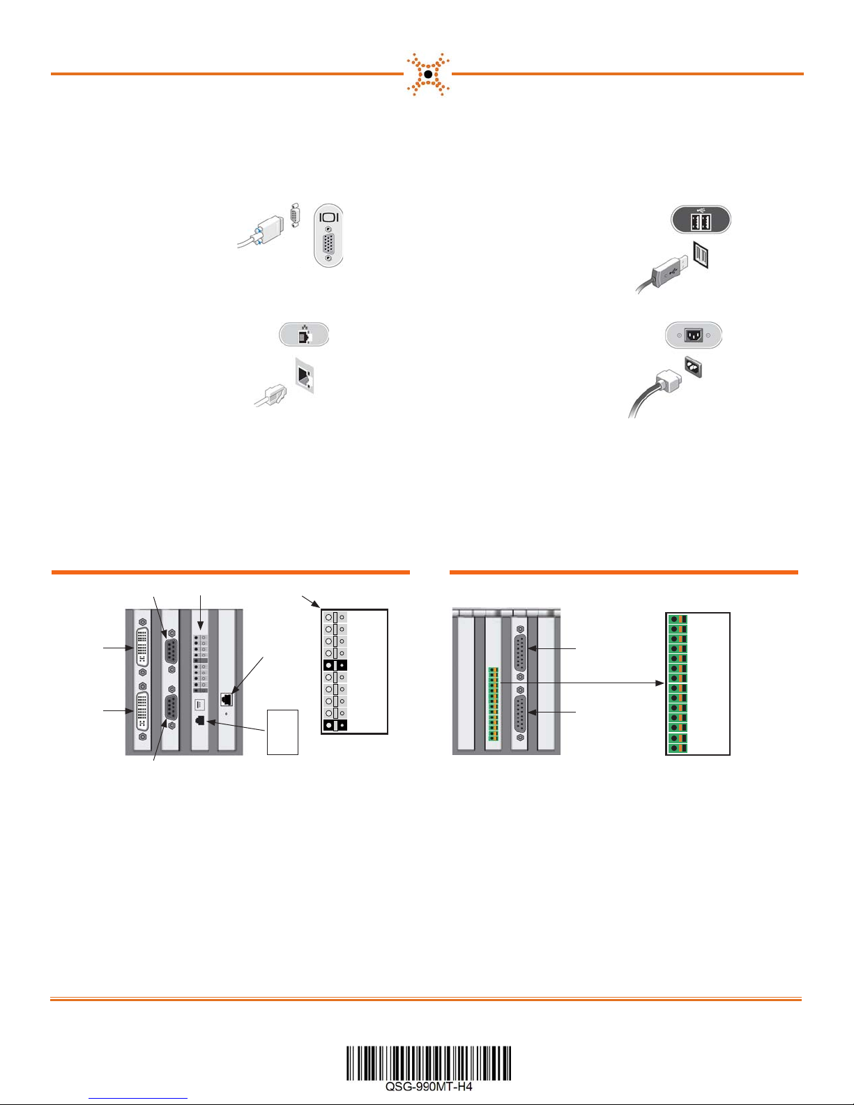
1. Connect the monitor
using a VGA cable
3. Connect network
cable(s) to Ethernet
port(s).
5. Connect the video cable(s) to the video capture board for
analog and hybrid systems. (AH, PH systems only. AI systems
do not include expansion cards. )
AH Series Systems
Audio In CH9 - CH16
Sensors and Control Terminals
2. Connect a USB device,
such as a keyboard
or mouse.
4. Connect the power
cable(s).
PH Series Systems
Video In
CH17 - CH32
Video In
CH1 - CH16
Audio In CH1 - CH8
4
Network
card
RS485
Terminals:
TX+
TX–
RX+
RX–
Control 1
Control 2
Control 3
Control 4
Ground
Sensor 1
Sensor 2
Sensor 3
Sensor 4
Ground
Video In
CH9 - CH16
Audio In
CH3 - CH4
(PH only)
Video In
CH1 - CH8
Audio In
CH1 - CH2
(PH only)
Sensor 1
Ground
Sensor 2
Ground
Sensor 3
Ground
Sensor 4
Ground
Relay 2
Ground
Relay 1
Ground
RS485 TRX +
RS485 TRX −
Copyright © 2012, 2013 DIGIOP, Inc. • Indianapolis, IN • tel: 800.968.3606 • fax: 317.663.2077 • www.digiop.com
DIGIOP is a registered trademark of DIGIOP, Inc. All rights reserved.
 Loading...