

Page 1
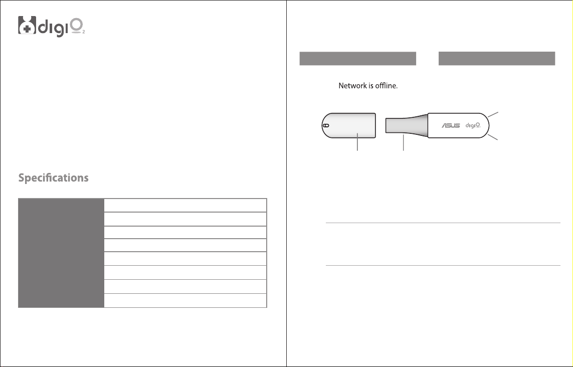
LED status indicators
Care Pal Dongle
Thank you for purchasing an digiO2 product!
The Care Pal dongle is a Bluetooth dongle that integrates data from
compatible Bluetooth-enabled sphygmometers, electrocardiograms,
pulse oximeters, blood glucose meters, weighing scales, and
thermometers.
Using the Care Pal dongle, data from these compatible medical devices
may be sent to a paired PC via wireless and secured transfers.
I/O port
Storage capacity
Bluetooth
LED indicators
Rating
Supported OS
Operation Environment
Storage Environment
USB 2.0
32 MB for 30-day data storage
4.0 class 2
2
5Vdc, 100mA
Windows® 8, Windows® 7, Windows® XP
10~40C (50~104F), 10% to 95% RH
-20~50C (-4~122F), 5% to 95% RH (Non-condensing)
Network LED
Color Status
Blue Network is online.
Orange
dongle cover
USB connector
Bluetooth LED
Color
Status
Blue
Bluetooth is enabled.
Orange
Bluetooth is disabled.
Network LED
Bluetooth LED
Installing the Care Pal dongle software
IMPORTANT! Ensure that your system runs .Net Framework 3.5 before
installing the
www.microsoft.com/en-us/download/details.aspx?id=21#overview
1. Turn on your computer or laptop then connect the
dongle to a USB 2.0 port.
2. Under My Computer, open the
then select eHealthSetup.
Care Pal
dongle software. You may download this version via
Care Pal
dongle’s storage drive
Care Pal
3. Choose Yes in the succeeding window to begin the installation
process.
Page 2
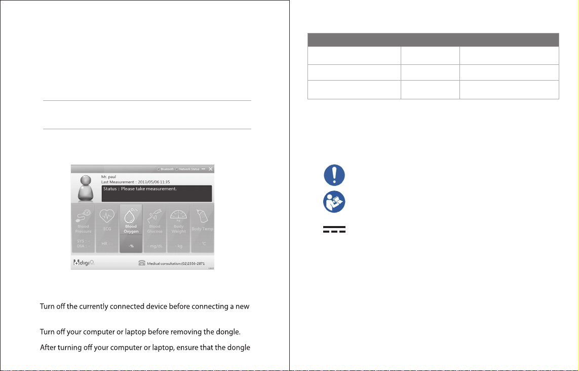
Using your Care Pal dongle
Troubleshooting
1. Turn on your laptop or computer.
2. Insert the
Care Pal
dongle in an available USB 2.0 port on your
laptop or computer.
3. Turn on the bluetooth device you would like to pair with your
Care Pal
dongle.
IMPORTANT! Ensure that all the devices are within a 3-meter range from
the dongle.
4. The following screen appears to prompt you to input your current
data using the compatible bluetooth device.
Safety tips when using your Care Pal dongle
•
device.
•
•
is also removed to avoid overwriting it with new data.
Problems
LED display does not light up No power Make sure that your PC is powered on.
Network LED display turns Orange Network is oine Check your PC network is workable.
Bluetooth LED display turns Orange Bluetooth is disable Unplug your dongle and insert it again.
Cause Suggested Actions
Marks and Abbreviation
ISO 7010-M001
ISO 7010-M002
IEC 60417-5031
WARNING – if the enclosure of this device is damaged, please do not use it, electrical shock hazard may
occur.
WARNING - Do not modify this equipment without authorizaon of the manufacturer.
Accessory equipment connected to the analog and digital interfaces must be in compliance with the
respecve naonally harmonized IEC standards (i.e. IEC 60950 for data processing equipment, IEC 60065
for video equipment, IEC 61010-1 for laboratory equipment, and IEC 60601-1 for medical equipment.)
Furthermore all configuraons shall comply with the system standard IEC 60601-1-1. Anyone who
connects addional equipment to the signal input part or signal output part is configuring a medical
system, and is therefore, responsi¬ble that the system complies with the requirements of the system
standard IEC 60601-1-1. The unit is for exclusive interconnecon with IEC 60601-1 cerfied equipment in
the paent environment and IEC 60XXX cerfied equipment out¬side of the paent environment. If in
doubt, consult the technical services department or your local representave.
General mandatory acon sign
Refer to instrucon manual/booklet
NOTE: On ME EQUIPMENT “Follow instrucons for use”
Direct current
Page 3

Cleaning Instructions
Wipe with a dry cloth
•
Disposing of your old product
Within the European Union
EU-wide legislaon, as implemented in each Member State, requires that waste electrical and electronic
products carrying the mark (le) must be disposed of separately from normal household waste. This
includes monitors and electrical accessories, such as signal cables or power cords. When you need to
dispose of your display products, please follow the guidance of your local authority, or ask the shop
where you purchased the product, or if applicable, follow any agreements made between yourself.
The mark on electrical and electronic products only applies to the current European Union Member
States.
The model CPW-103 is intended for use in the electromagnetic environment specified below. The customer or the user of
the model CPW-103 should assure that it is used in such an environment.
Immunity test IEC 60601
Electrostatic
discharge (ESD)
IEC 61000-4-2
Electrical fast
transient/burst
IEC 61000-4-4
Surge
IEC 61000-4-5
interruptions and
voltage variations
on power supply
input lines
IEC 61000-4-11
Power frequency
(50/60 Hz)
magnetic field
IEC 61000-4-8
NOTE UT is the a.c. mains voltage prior to application of the test level.
Guidance and manufacturer’s declaration – electromagnetic immunity
test level
6 kV contact
8 kV air
2 kV for power
supply lines
1 kV for input/output
lines
1 kV line(s) to line(s)
2 kV line(s) to earth
<5 % UT
(>95 % dip in UT)
for 0,5 cycle
40 % UT
(60 % dip in UT)
for 5 cycles
70 % UT
(30 % dip in UT)
for 25 cycles
<5 % UT
(>95 % dip in UT)
for 5 sec
3 A/m
Compliance level Elect romagnetic environment –
6 kV contact
8 kV air
2 kV for power
supply lines
1 kV for input/output
lines
1 kV line(s) to line(s)
2 kV line(s) to earth
<5 % UT
(>95 % dip in UT)
for 0,5 cycle
40 % UT
(60 % dip in UT)
for 5 cycles
70 % UT
(30 % dip in UT)
for 25 cycles
<5 % UT
(>95 % dip in UT)
for 5 sec
3 A/m
Floors should be wood, concrete
or ceramic tile. If floors are
covered with synthetic material,
the relative humidity should be at
least 30 %.
Mains power quality should be
that of a typical commercial or
hospital environment.
Mains power quality should be
that of a typical commercial or
hospital environment.
Mains power quality should be
that of a typical commercial or
hospital environment. If the user
of the model CPW-103 requires
continued operation during power
mains interruptions, it is
recommended that the model
CPW-103 be powered from an
uninterruptible power supply or a
battery.
Power frequency magnetic fields
should be at levels characteristic
of a typical location in a typical
commercial or hospital
environment.
guidance
Page 4

The model CPW-103 is intended for use in the electromagnetic environment specified below. The customer or the user of
the model CPW-103 should assure that it is used in such an environment.
RF emissions
CISPR 11
RF emissions
CISPR 11
Harmonic emissions
IEC 61000-3-2
Voltage fluctuations/
flicker emissions
IEC 61000-3-3
The model CPW-103 is intended for use in an electromagnetic environment in which radiated RF disturbances are
controlled. The customer or the user of the model CPW-103 can help prevent electromagnetic interference by maintaining
a minimum distance between portable and mobile RF communications equipment (transmitters) and the model CPW-103
as recommended below, according to the maximum output power of the communications equipment.
Rated maximum output
power of transmitter
For transmitters rated at a maximum output power not listed above, the recommended separation distance d in metres (m)
can be estimated using the equation applicable to the frequency of the transmitter, where P is the maximum output power
rating of the transmitter in watts (W) according to the transmitter manufacturer.
NOTE 1 At 80 MHz and 800 MHz, the separation distance for the higher frequency range applies.
NOTE 2 These guidelines may not apply in all situations. Electromagnetic propagation is affected by absorption and
reflection from structures, objects and people.
Guidance and manufacturer’s declaration – electromagnetic emissions
ecnailpmoC tset snoissimE Electromagnetic environment – guidance
Group 1 The model CPW-103 uses RF energy only for
Class B The model CPW-103 is suitable for use in all
Class A
Not applicable
portable and mobile RF communications equipment and the model CPW-103
W
Recommended separation distances between
Separation distance according to frequency of transmitter
150 kHz to 80 MHz
d = 1,2
P
its internal function. Therefore, its RF
emissions are very low and are not likely to
cause any interference in nearby electronic
equipment.
establishments, including domestic
establishments and those directly connected
to the public low-voltage power supply
network that supplies buildings used for
domestic purposes.
m
80 MHz to 800 MHz
d = 1,2P
800 MHz to 2,5 GHz
d = 2,3P
32,0 21,0 21,0 10,0
37,0 83,0 83,0 1,0
3,2 2,1 2,1 1
3,7 8,3 8,3 01
32 21 21 001
Guidance and manufacturer’s declaration – electromagnetic immunity
The model CPW-103 is intended for use in the electromagnetic environment specified below. The customer
or the user of the model CPW-103 should assure that it is used in such an environment.
Immunity test IEC 60601 test level Compliance
level
Conducted RF
IEC 61000-4-6
Radiated RF
IEC 61000-4-3
3 Vrms
150 kHz to 80 MHz
3 V/m
80 MHz to 2,5 GHz
3 Vrms
3 V/m
Electromagnetic environment –
guidance
Portable and mobile RF communications
equipment should be used no closer to
any part of the model CPW-103, including
cables, than the recommended separation
distance calculated from the equation
applicable to the frequency of the
transmitter.
Recommended separation distance
d = 1,2
P
d = 1,2
80 MHz to 800 MHz
P
d = 2,3
800 MHz to 2,5 GHz
P
where P is the maximum output power
rating of the transmitter in watts (W)
according to the transmitter manufacturer
and d is the recommended separation
distance in metres (m).
Field strengths from fixed RF transmitters,
as determined by an electromagnetic site
Page 5

survey, a should be less than the
compliance level in each frequency range.
b
Interference may occur in the vicinity of
equipment marked with the following
symbol:
NOTE 1 At 80 MHz and 800 MHz, the higher frequency range applies.
NOTE 2 These guidelines may not apply in all situations. Electromagnetic propagation is affected by
absorption
and reflection from structures, objects and people.
a
Field strengths from fixed transmitters, such as base stations for radio (cellular/cordless) telephones and
land mobile radios, amateur radio, AM and FM radio broadcast and TV broadcast cannot be predicted
theoretically with accuracy. To assess the electromagnetic environment due to fixed RF transmitters, an
electromagnetic site survey should be considered. If the measured field strength in the location in which
the model CPW-103 is used exceeds the applicable RF compliance level above, the model CPW-103
should be observed to verify normal operation. If abnormal performance is observed, additional measures
may be necessary, such as reorienting or relocating the model CPW-103.
b
Over the frequency range 150 kHz to 80 MHz, field strengths should be less than 3 V/m.
Page 6

Federal Communications Commission (FCC) Statement
15.21
You are cautioned that changes or modifications not expressly approved by
the part responsible for compliance could void the user’s authority to operate
the equipment.
15.105(b)
This equipment has been tested and found to comply with the limits for a
Class B digital device, pursuant to part 15 of the FCC rules.
These limits are designed to provide reasonable protection against harmful
interference in a residential installation.
This equipment generates uses and can radiate radio frequency energy and,
if not installed and used in accordance with the instructions, may cause
harmful interference to radio communications.
However, there is no guarantee that interference will not occur in a particular
installation.
If this equipment does cause harmful interference to radio or television
reception, which can be determined by turning the equipment off and on,
the user is encouraged to try to correct the interference by one or more of the
following measures:
-Reorient or relocate the receiving antenna.
-Increase the separation between the equipment and receiver.
-Connect the equipment into an outlet on a circuit different from that to which
the receiver is connected.
-Consult the dealer or an experienced radio/TV technician for help.
This device complies with part 15 of the FCC Rules. Operation is subject to
the following two conditions:
1) this device may not cause interference and
2) this device must accept any interference, including interference that may
cause undesired operation of the device.
FCC RF Radiation Exposure Statement:
This equipment complies with FCC radiation exposure limits set forth for an
uncontrolled environment.
End users must follow the specific operating instructions for satisfying RF
exposure compliance.
This transmitter must not be co-located or operating in conjunction with any
other antenna or transmitter.
ETH-102 wireless system configuration and operation:
1. Quality of service: BQB test
2. Security requirements: Key in Pin code "0000".
3. If users paired with PC was unsuccessful, the data was not shown it on the
LCM. Users can repairing and upload the it again.
 Loading...