

Page 1
Installation
Guide
DGOZ
-
EHUB
-4G-
2S
DIGINET.NET.AU
RAPIX Lighting Control System - eHub
Designed in Australia to
meet Australian Standards
and installation conditions
Page 2

RAPIX Lighting Control System RAPIX Lighting Control System - eHub
2
1. Product item
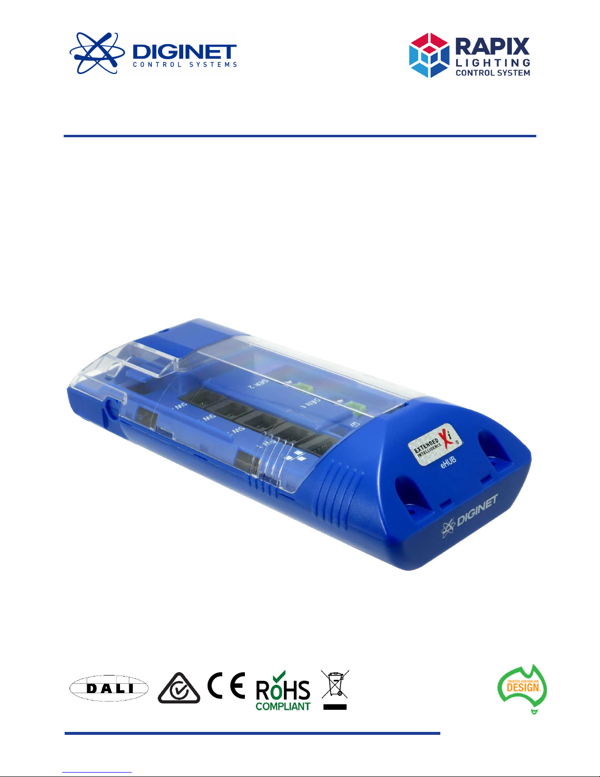
This guide provides user operation and product specification information for the RAPIX Lighting Control System
‘eHub’, item number DGOZ-EHUB-4G-2S.
2. Product package contents
The eHub package includes the following:
• 1 x eHub
• 1 x 12V dc SELV power supply.
3. Important notes and safety information
WARNING
– Electric shock may result in serious injury or death. Follow all warnings in this
guide and on the product while working in accordance with the latest electrical safety
practices.
• The eHub does not have a mains supply connection. DALI Lines operate on an ELV dc supply between 9.5V
and 22.5V but must be considered at mains potential due to basic equipment isolation and cable
segregation between mains and DALI. DALI is Functional Extra Low Voltage (FELV) as defined by standard
IEC61140
• The installer must be suitably qualified and should work in accordance with standard safety procedures
for mains-powered electrical equipment
• Appropriate segregation is to be maintained between the SELV/Data cabling and mains/DALI Line cabling
in accordance with local regulations
• There are no user serviceable parts inside the eHub. Do not attempt to disassemble or operate the device
with any covers removed
• The eHub is intended for indoor use
• Outdoor installations will require the device to be housed in a suitable IP rated enclosure
• Consult the manufacturer’s instructions for Lighting Control Gear and other DALI units that may be
connected to the DALI Lines.
If you require information or assistance regarding the installation, configuration, or operation of the eHub,
contact Technical Services at Diginet Control Systems. Contact details are provided on the back cover of this guide
and also at www.diginet.net.au
Page 3
RAPIX Lighting Control System RAPIX Lighting Control System - eHub
3
4. Product summary and capabilities
The eHub is a RAPIX lighting control system device which connects between input peripherals and a DALI line.
The eHub manages input peripheral power requirements, as well as embedded logical functions and DALI
communications for these connected input peripherals. The connected input peripherals, such as RAPIX modular
switches and PIR sensors, are then able to communicate with a DALI Line.
The unit includes four inputs for connecting to RAPIX smart input peripherals, and two additional input
connections for occupancy sensors and/or dry contacts.
The eHub is a compact unit which fits through a standard 90mm downlight ceiling hole and is suitable for locating
in a ceiling void.
The eHub is configured via the Diginet RAPIX software suite.
5. Product features
• Powered via external 12V dc SELV power supply
• Input sockets for quick and easy input peripheral connection
• Segregated terminal block for DALI Line connections
• LED indicators for power, DALI and Ethernet
• Suitable for mounting in a ceiling void
• Fits through a 90mm downlight hole
• Programmed via DALI
• Four input connections for RAPIX smart input peripherals
• Two input connectors for occupancy sensors and/or dry contacts input peripherals
• Actions for connected input peripherals are configurable. For example, a RAPIX modular switch can be
configured as a toggle dimmer, memory dimmer, long press fade time, double tap action and many other
configurations
• Support for 32 'Zones', Zones being collections of DALI Groups and/or DALI Short Addresses
• Support for up to 16 DALI scenes and (additionally) 16 RAPIX scenes.
6. Mounting the eHub
The eHub is suitable for mounting in a variety of
indoor locations, including above suspended tile
ceilings and fixed plasterboard ceilings.
The eHub has an ingress protection rating of IP20 and
as such is not protected against moisture ingress. It is
therefore not suitable for mounting in an outdoor
environment without being housed in a suitable
weatherproof enclosure.
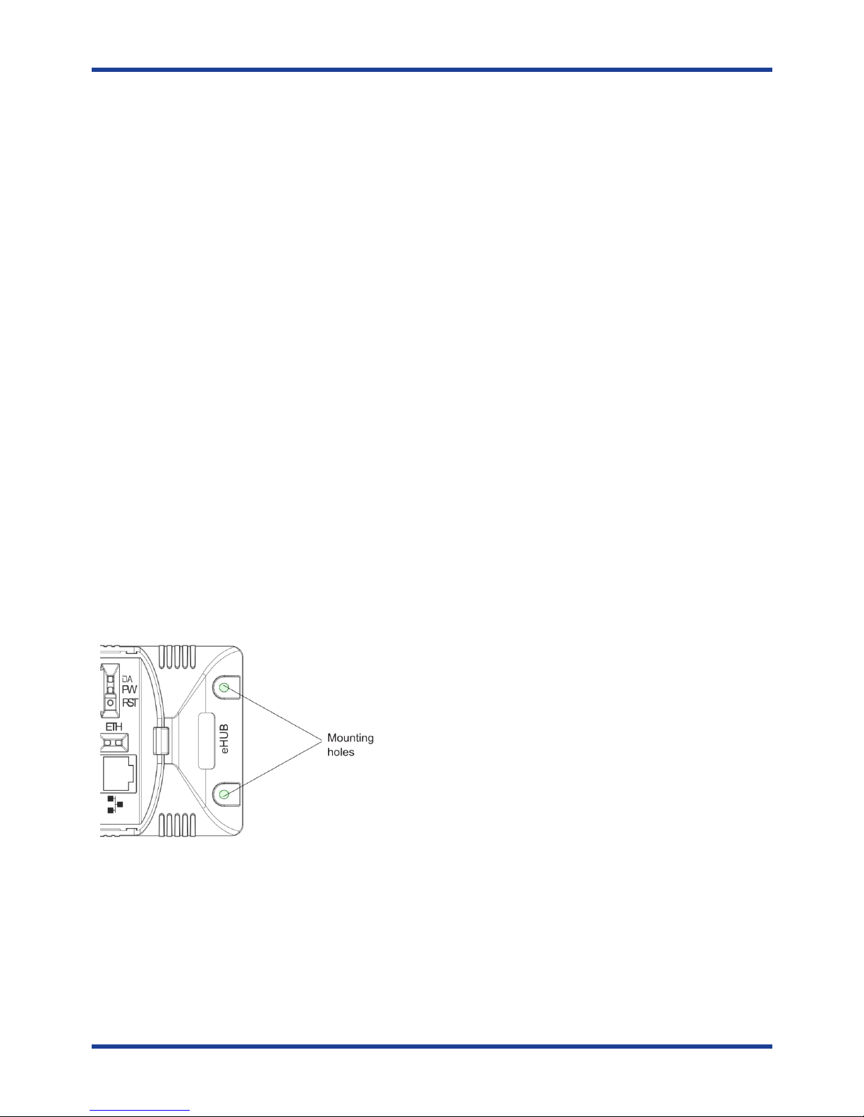
The eHub includes two 6mm mounting holes. These
can be used to anchor the eHub in a suitable location,
typically using fixing screws or cable ties.
Page 4
RAPIX Lighting Control System RAPIX Lighting Control System - eHub
4
7. Inputs and output connections
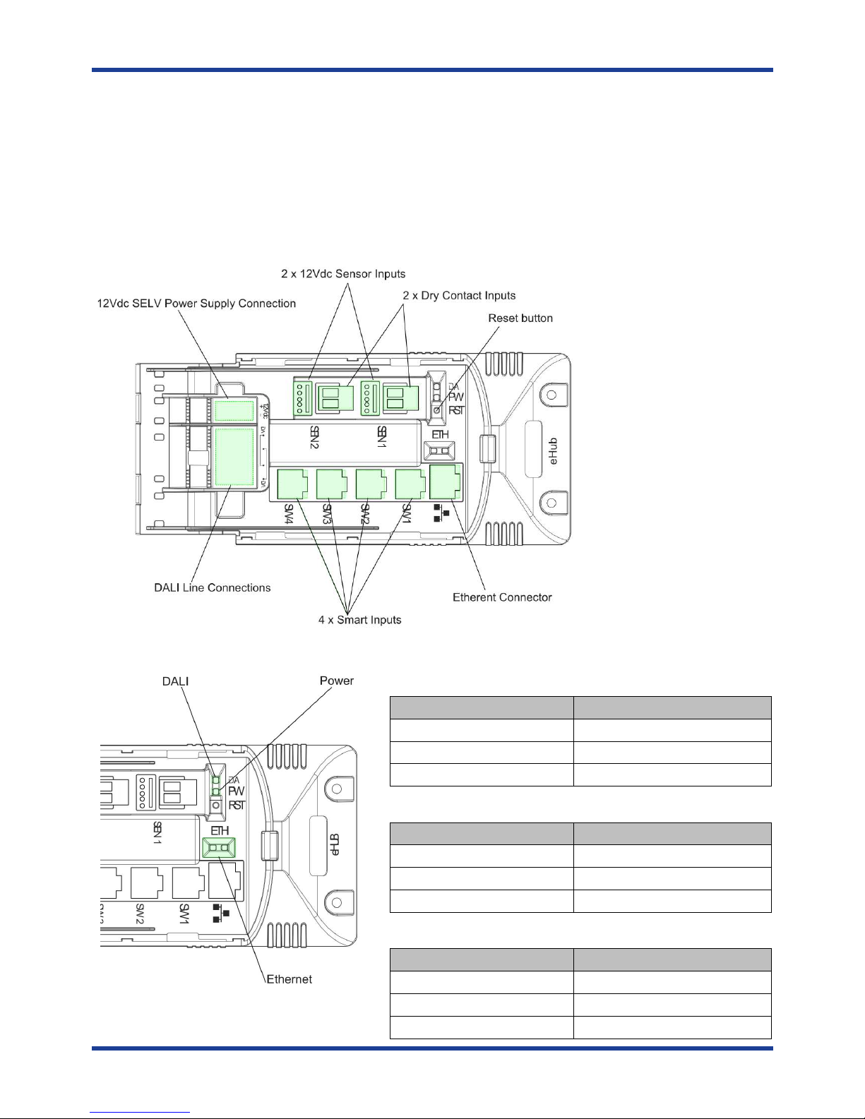
The eHub connects to the following:
• 12V dc SELV power supply connection
• A DALI Line, with up to 64 DALI devices (each with a DALI Short Address) connected to the line
• Four connections for RAPIX smart input peripherals
• Two input peripheral connections for dry contacts and two 12V dc sensors (Note: each pair of dry contact
and 12V dc sensor inputs are internally connected in parallel)
• An Ethernet connection (future use)
8. Indicators
Power Indicator
Indicator
Indicator Meaning
Red Power available
Red -
Flash OFF
Received Data from Inputs
OFF eHub not powered
DALI Indicator
Indicator
Indicator Meaning
Green
- Flash OFF
DALI available
Green
- Flash ON
DALI not available
Green Fast Flashing ON/OFF
DALI communications
Ethernet Indicator
Indicator
Indicator Meaning
Green ON
Link/Active
Green OFF
No Link
Yellow Flashing
Data activity
Page 5
RAPIX Lighting Control System RAPIX Lighting Control System - eHub
5
9. Powering connected input peripherals
The eHub supplies power to all connected input peripherals such as RAPIX modular switches and 12V dc sensors.
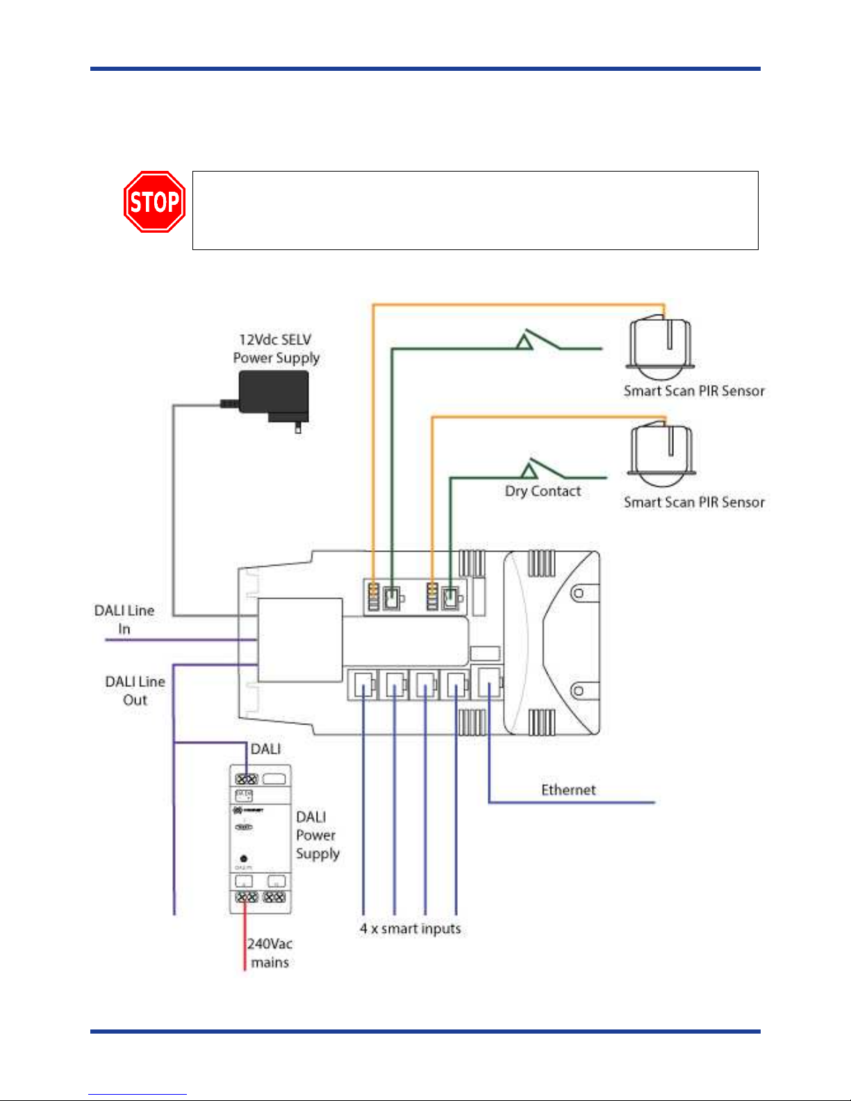
10. Connections Overview
WARNING
-
DALI Lines
must be considered at 240Vac electrical mains potential due to basic
equipment isolation and cable segregation between mains and DALI.
Electric shock may result in serious injury or death. Follow all warnings in this guide and on
the product while working in accordance with the latest electrical safety practices.
Page 6
RAPIX Lighting Control System RAPIX Lighting Control System - eHub
6
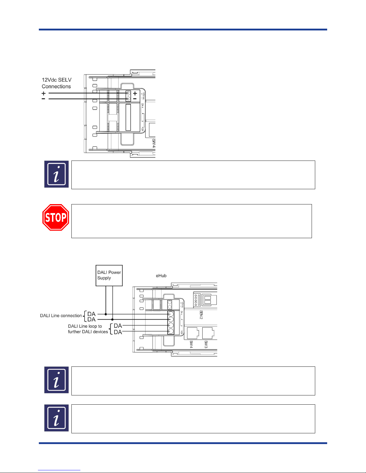
11. Connecting 12V dc SELV power supply
The eHub is powered via an external 12V dc SELV power supply, supplied with the unit. The power supply is
connected as shown below.
A third part
y 12V dc
SELV powered supply can be used to power the eHub. Any third party
power supply used with the eHub must be 12V dc regulated and must be capable of supplying
1.5A @ 12V dc.
12. Connecting to a DALI Line
WARNING
-
DALI Lines
must be considered at 240Vac electrical mains potential due to basic
equipment isolation and cable segregation between mains and DALI.
Electric shock may result in serious injury or death. Follow all warnings in this guide and on
the product while working in accordance with the latest electrical safety practices.
The eHub can be connected to a single DALI Line, as shown below. Separate DALI loop-off terminals are also
provided.
The DALI
L
ine cable has two conductors
and these are not polarity sensitive. DALI Line cabling
must be double insulated and mains rated.
Each DALI Line requires an external
DALI compliant power supply to be connected before it
will operate. A Diginet DALI Power Supply, item number DGLMPS01 (purchased separately),
can be connected to each DALI Line to fulfil this requirement.
Page 7
RAPIX Lighting Control System RAPIX Lighting Control System - eHub
7
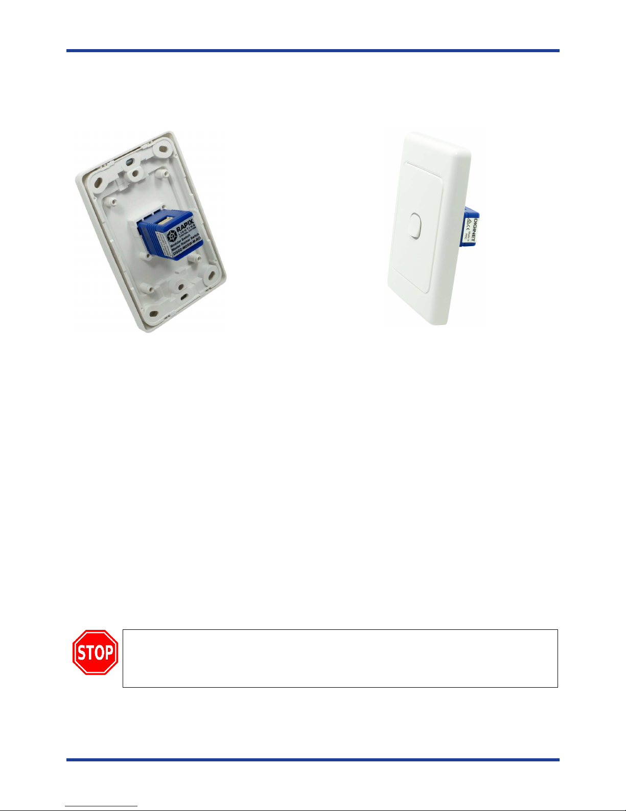
13. Connecting RAPIX modular switches
RAPIX modular switches are wall switches for the RAPIX Lighting Control System which fit in standard
Australian wall switch grid plates. RAPIX modular switches function as eHub input peripherals.
A
RAPIX modular
master
switch
mounted in a typical Australian one
-
gang wall switch grid plate.
RAPIX modular switches are available as ‘masters’ or ‘slaves’.
Master RAPIX modular switches connect directly to the eHub.
Slave RAPIX modular switches connect via master RAPIX modular switches
RAPIX modular switches are configured in RAPIX software to perform a wide range of functions and each modular
switch (both masters and slaves) includes two software configurable LED indicator colours, white and amber.
13.1. Features
• Two configurable LED colours, white and amber
• Fits standard Australian wall plate apertures
• Master RAPIX modular switches connect to the eHub and are powered via the eHub
• Slave RAPIX modular switches connect to a master and are powered via the master
• Typical functions include
• Toggle on / off
• Fade lights up or down
• Start or cancel a timer
• Recall a fixed level
• Toggle between off and the current Level
• Issue a scene
All commissioning is carried on via Diginet RAPIX software suite. The configuration is downloaded to the eHub via
a DALI line.
Do not
connect
RAPIX modular switches
to the building/house ac mains supply.
RAPIX modular switches are control devices which are powered by the eHub via an SELV
connection and must only be connected as described in this guide. That is, master switches are
connected to the eHub, slave switches are connected to master switches.
Page 8
RAPIX Lighting Control System RAPIX Lighting Control System - eHub
8
13.2. Range
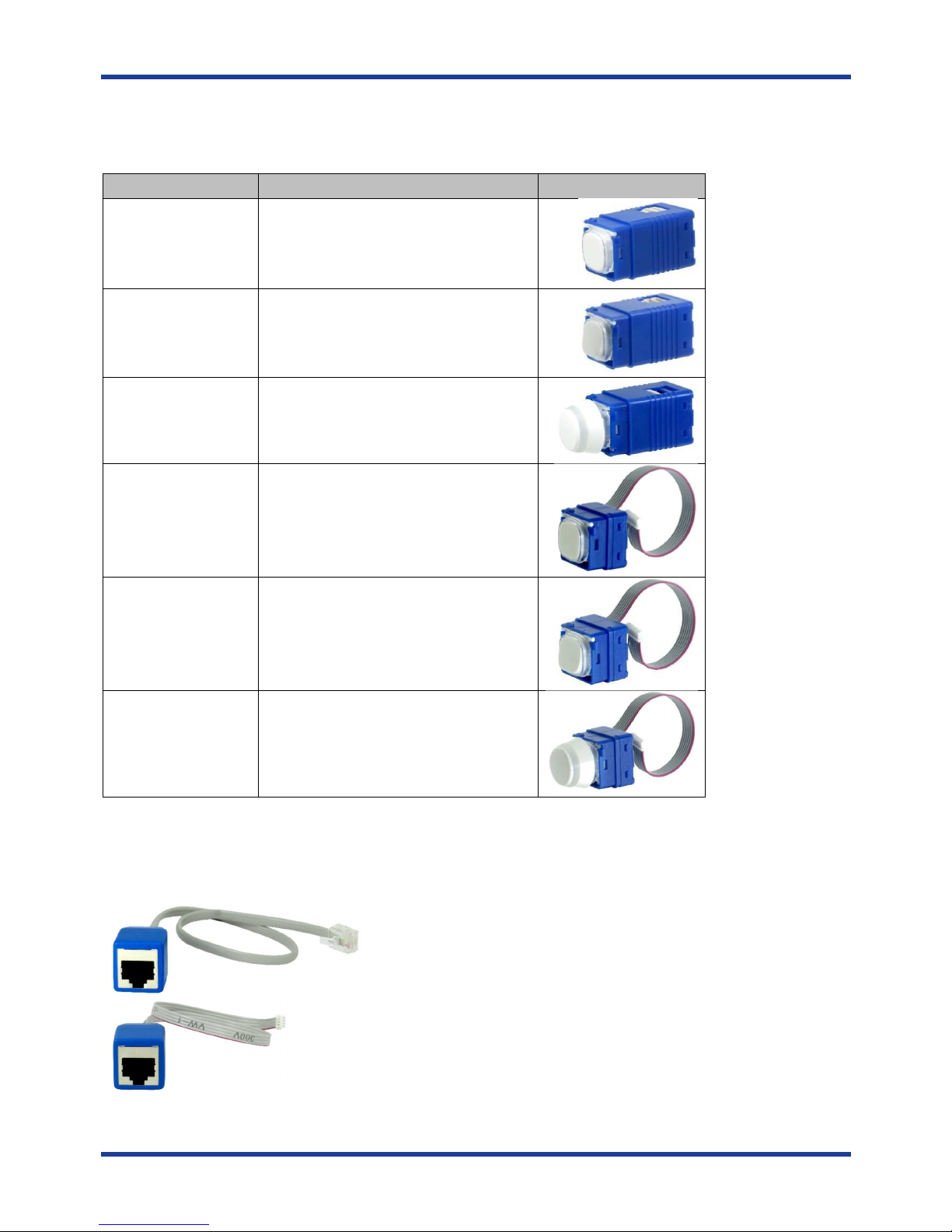
The following RAPIX modular switches can be connected to each of the four smart input peripheral connectors on
the eHub.
Diginet Part Number
Description
DGOZ
-
MOSW
-M-PB
RAPIX
m
odular switch
– Push Button
Master
DGOZ
-
MOSW
-M-RO
RAPIX
m
odular switch
– Rocker Master
DGOZ
-
MOSW
-M-RE
RAPIX
m
odular switch
– Rota
ry Master
DGOZ
-
MOSW
-S-PB
RAPIX
m
odular switch
– Push Button
Slave
DGOZ
-
MOSW
-S-RO
RAPIX
m
odular switch
– Rocker Slave
DGOZ
-
MOSW
-S-RE
RAPIX
m
odular switch
– Rotary Slave
Note that RAPIX modular switches are purchased separately.
14. Connecting RAPIX modular switches to the eHub
Each master RAPIX modular switch is supplied with the following patch leads.
eHub to RJ-45 patch lead
Master RAPIX modular switch to RJ-45 patch lead
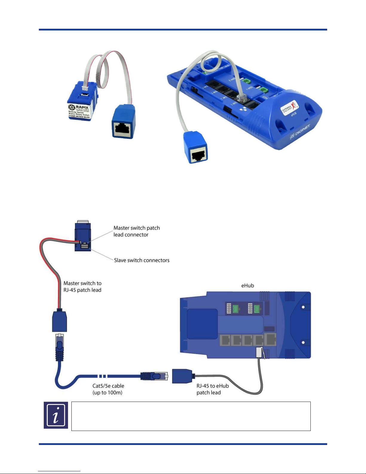
These two patch leads are used in conjunction with standard Cat5/Cat5e cable and RJ-45 connectors to connect
master RAPIX modular switches in the eHub. See the pictures and diagram on the following page.
Page 9
RAPIX Lighting Control System RAPIX Lighting Control System - eHub
9
14.1. RAPIX modular switch eHub patch lead connections
Connection between a m
aster
RAPIX modular
switch and RJ-45 patch lead
Connection between
the eHub and RJ
-
45 patch lead
14.2. Connections from the eHub to a master RAPIX modular switch
The diagram below shows the connections between the eHub and a master RAPIX modular switch.
The maximum distance between a master RAPIX modular switch and the eHub is 100m.
All m
aster
RAPIX modular switches
(push button, rocker and rotary
) are connected to the
eHub in the same way as indicated above
Page 10
RAPIX Lighting Control System RAPIX Lighting Control System - eHub
10
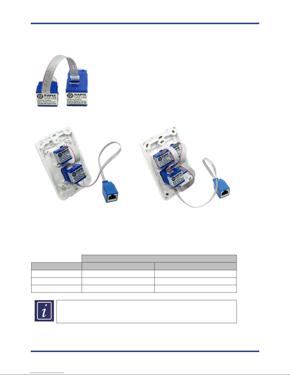
15. Connecting masters to slaves
Slave RAPIX modular switches connect directly to masters. Slaves have an integrated flying lead with a male
connector. Masters have matching female sockets.
Connection between a
master and slave RAPIX
modular switch
15.1. Typical installed connections
Typical connections between master and slave
rotary RAPIX modular switches in a two gang grid
plate
Typical connections between
a
master and
three
slave RAPIX modular switches in a four gang grid
plate
15.2. Maximum number of master / slave connections
The number of slave RAPIX modular switches supported by each type of master are shown in the table below.
Number of possible slaves connected
Master type
Slave Push Button
s or Rocker
s
Slave Rotary
Push Button
Up to 5
N/A
Rocker
Up to 5
N/A
Rotary
N/A 1
The maximum permissible distance between th
e master and slaves
RAPIX modular
switches is limited to the pre-terminated slave cable length. This pre-terminated cable
must not be extended or shortened.
Page 11
RAPIX Lighting Control System RAPIX Lighting Control System - eHub
11
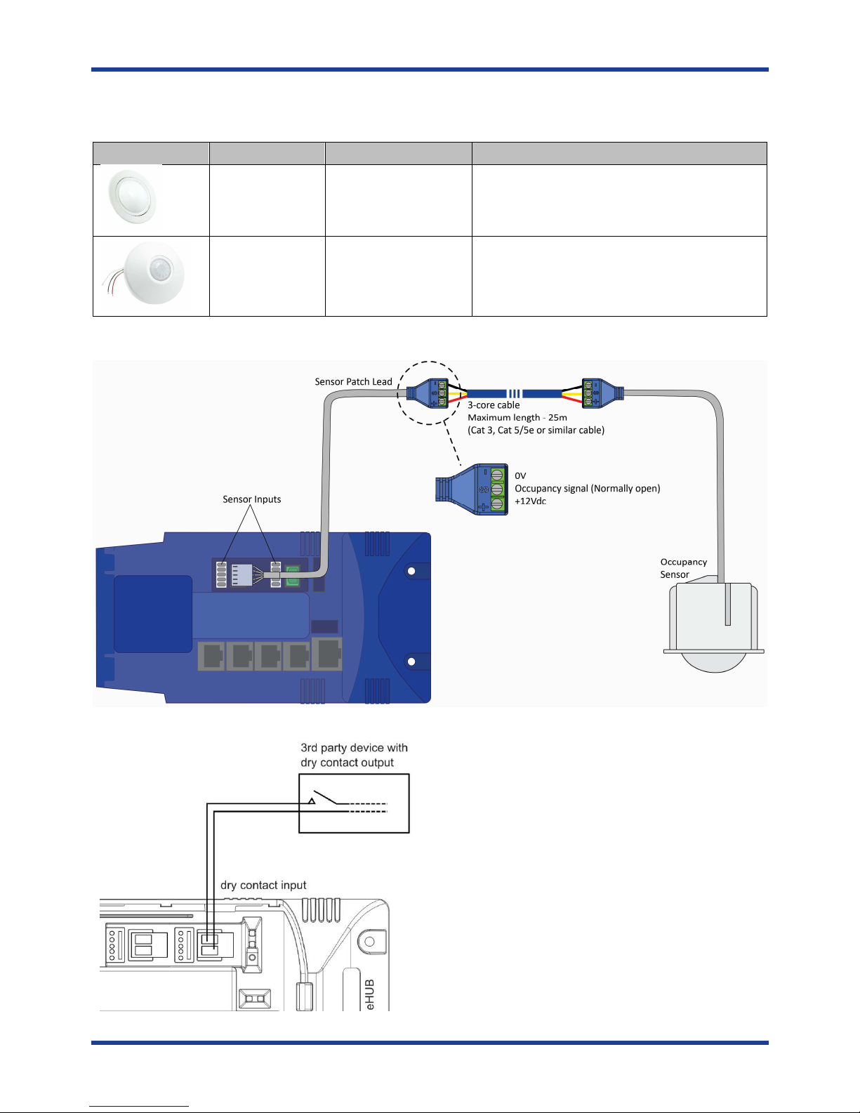
16. Connecting occupancy sensors to the eHub
The following occupancy sensors can be connected and powered from one of the two eHub sensor inputs.
Manufacture
Item Number
Description
Gerard Lighting
Diginet DGEMS360CL
Smart Scan PIR Sensor, 360 degree ceiling
mount, recessed
Sensor Switch
CM-
PDT-9-AU Sensor Switch dual technology sensor with PIR
and Microphonics detection, ceiling mounted
A sensor patch lead is provided with the above sensors and connected to the eHub as shown below.
17. Connecting a dry contact input
The eHub includes two separate dry contact inputs for
connecting contact closure outputs signals from 3rd
party devices into the eHub. Typical connections are
shown on this diagram.
The maximum cable length between the eHub and the
switch input is 50m.
Page 12
RAPIX Lighting Control System RAPIX Lighting Control System - eHub
12
18. Powering the eHub
The eHub has no power switch, therefore when connected to the 12V dc SELV power supply, it will power up.
19. Commissioning and testing
Commissioning of the eHub, which forms part of a complete RAPIX Lighting Control System, should be carried out
using the Diginet RAPIX software suite, which can be downloaded from the Diginet web site at diginet.net.au.
20. Resetting the eHub
Pressing and holding the recessed reset button (with a paperclip or similar) for 45 seconds will perform a
complete factory reset and all settings in the eHub will be lost.
A partial reset can be carried out by pressing and holding the recessed reset button for 10 seconds. This clears
most settings, but input peripheral device definitions and template information is kept.
21. Power surges
The eHub has no mains connection. However, induced voltages or surges may occur on electrical circuits and
communication cabling as a result of excessive voltages from external influences. Any induced voltages or surges
can damage electronic equipment. It is strongly recommended that the electrical and data installation be fitted
with suitable over-voltage protection at the electrical switchboard and IT cabinets to avoid these situations.
22. Insulation resistance testing
It is generally not a requirement to perform an IR test on DALI Lines. In the event it is required, the DALI line
cables must be disconnected from the eHub to conduct the test and then reconnected.
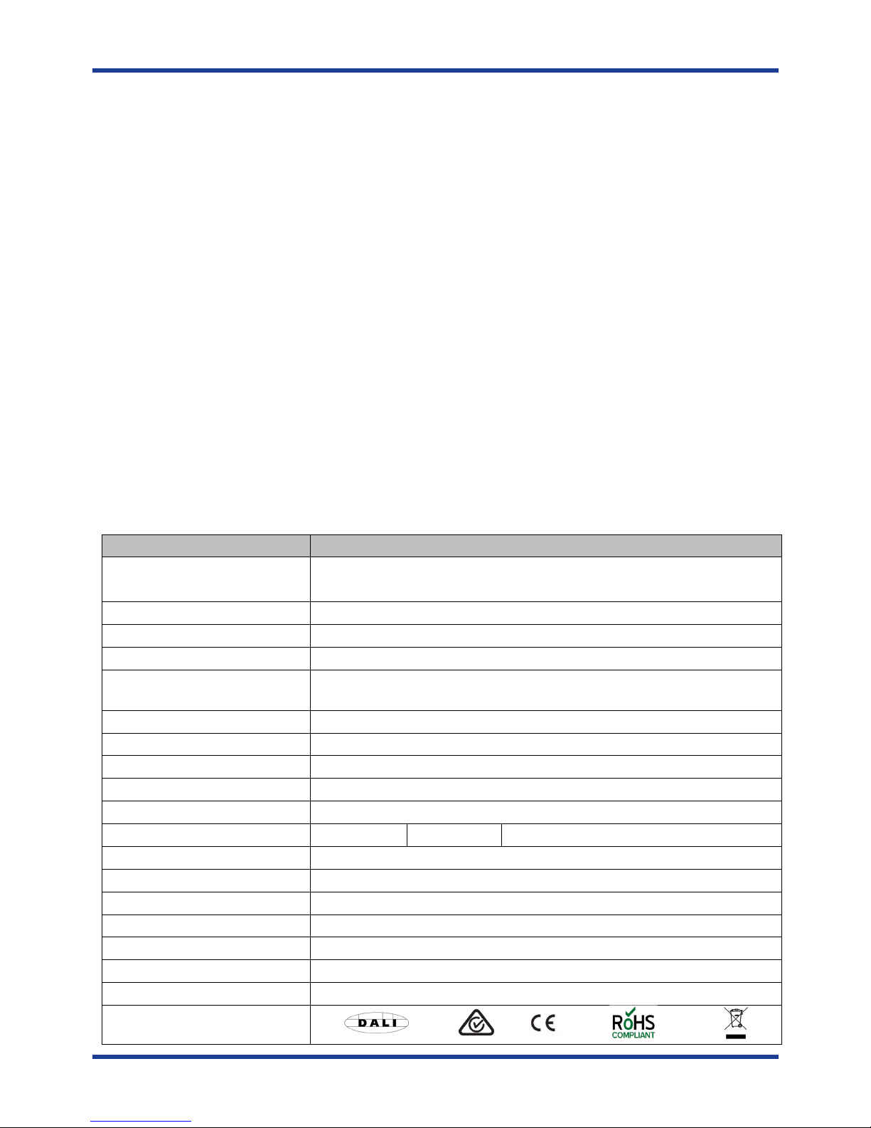
23. eHub specifications
Parameter
Specification
DALI
L
ine capacity
1 DALI line
, up to 64 devices with DALI Short Addresses can be connected
Note: The eHub itself does not require a DALI Short Address to be allocated
Max no.
of unit’s per
DALI
Line 25
(with Diginet DALI power supply, item number DGLMPS01)
DALI
L
ine operating voltage
18V dc (nominal), supplied by external DALI power supply
DALI L
ine current draw
2mA (nominal)
Power
External
SELV
power s
upply,
12V dc
regulated,
1.5A
(including
power
capacity for input peripheral devices)
Number
of smart i
nputs
4
Number of d
ry contact inputs
2 voltage free, isolated,
dry contact inputs (in pa
rallel with sensor inputs)
12V dc
Sensor inputs
2 sensor
inputs (in parallel with
dry-contact
inputs)
Ethernet Connection
10/100 Base
-
T, RJ45 connector
DALI connection
4 Tunnel
Terminal block
, each tunnel
suitable for 2 x 2.5sqmm
LED Indicators
Power
– Red
DALI
– Green
Ethernet
– Green (Link) + Yellow (D
ata)
External Power connector
Two tunnel terminal block for dc + and
-
Ambient operating temperature
0 to 50
○
C
Ambient storage temperature
-10 to 70
○
C
Humidity
0% to 95% RH non condensing
Ingress protection
IP20
Materials
Enclosure
– Flame retardan
t ABS
Weight
215g
Approvals
Page 13
RAPIX Lighting Control System RAPIX Lighting Control System - eHub
13
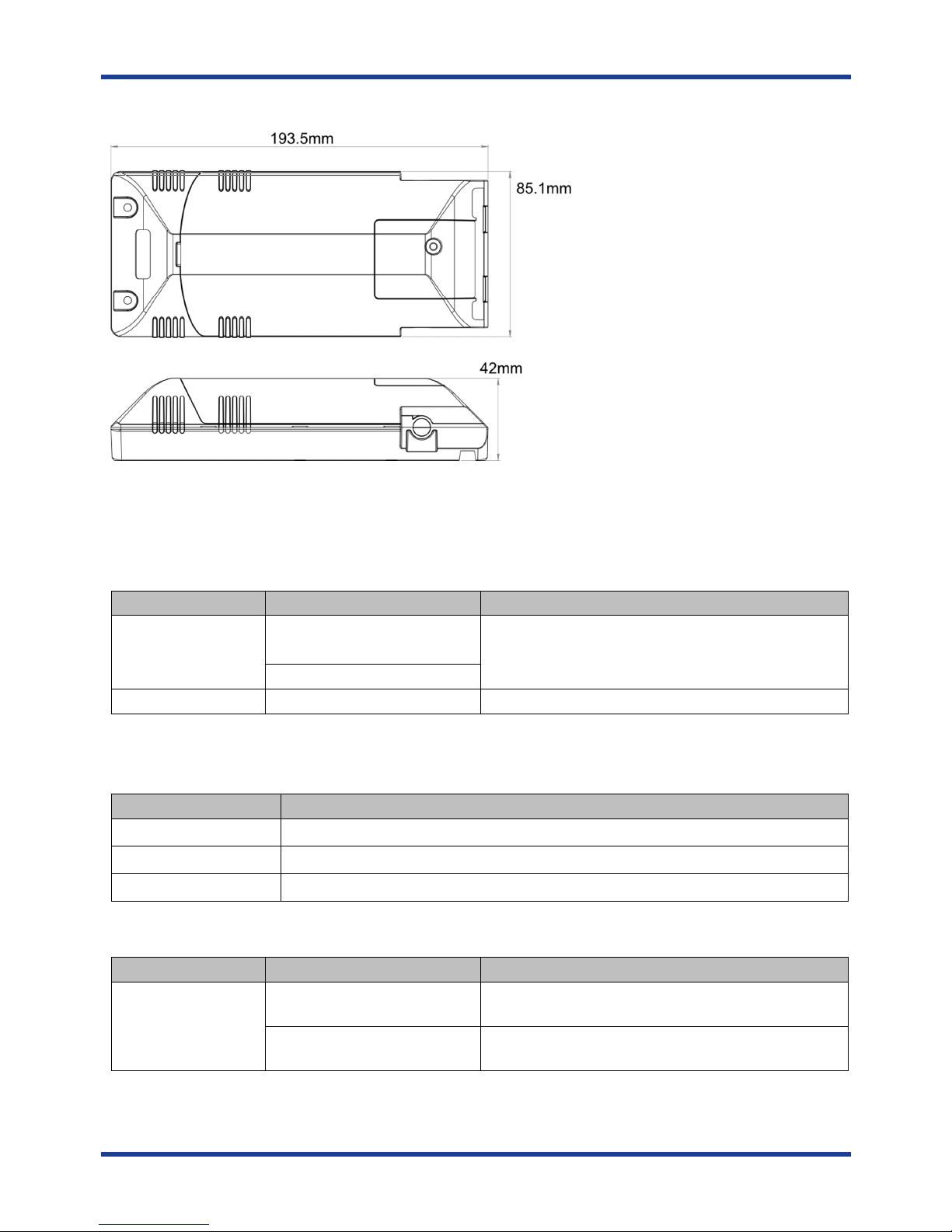
24. eHub dimensions
25. eHub standards and compliance
The
eHub
is designed to meet/exceed the following Australian and International standards.
Australian/New Zealand EMC and Electrical Safety Frameworks and Standards.
Regulation
Standard
Title
EMC AS/NZS CISPR 22:
2009
CISPR15
Information Technology Equipment
– Radio
Disturbance Characteristics – Limits and Methods of
Measurement
AS/NZS CISPR 22
-A:2010
Electrical Safety
AS/NZS 60950
-1:
2011
Information Technol
ogy Equipment
– Safety
The product is in conformity with the essential requirements of the following EC Directives and accordingly carries
the CE marking.
EC Council Directive
Title
2006/95/EC Low Voltage
2004/108/EC Electromagnetic Compatibility (EMC)
2011/65/EU
Restriction of Hazardous Substances (RoHS) in Electrical and Electronic Equipment
Other International Directives and Standards.
Regulation
Standard
Title
D
igital Addressable
Lighting Interface
(DALI)
IEC 62386
-
101 Digital Addressable Lighti
ng Interface
– Part 101:
General Requirements – System
IEC 62386
-
102 Digital Addressable Lighting Interface
– Part 102:
General Requirements – Control Gear
Page 14
RAPIX Lighting Control System RAPIX Lighting Control System - eHub
14
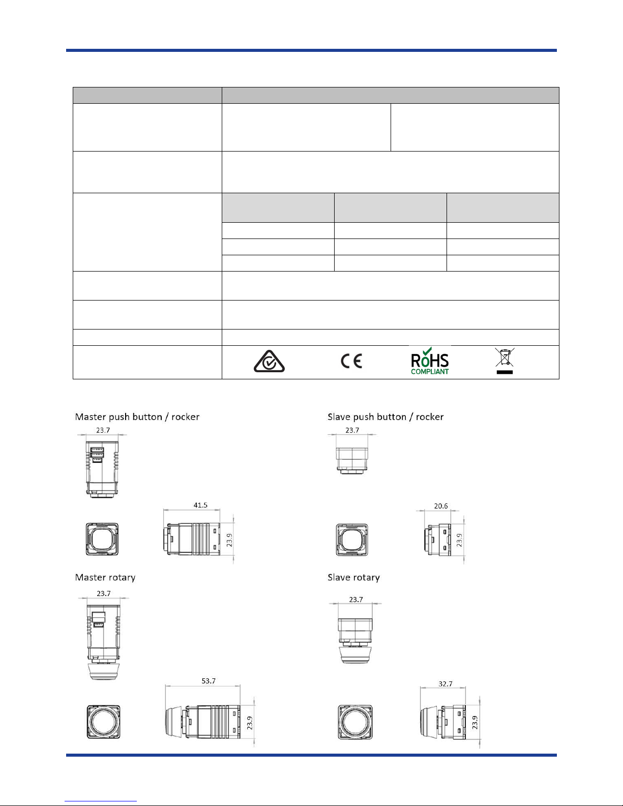
26. RAPIX modular switch range specifications
Parameter
Specification
Available types
Push Button
Master
Rocker Master
Rotary Master
Push Button Slave
Rocker Slave
Rotary Slave
LED colours
Master
and slave
RAPIX modular switches
include
both white and amber
LED indicators. The operation of these LEDs and LED colours is configured in
the RAPIX software tools
Number of slave
s
which can be
connected to a master
Master
switch
type
Slave push / rocker
switches
Slave rotary switches
Push Button
Up to 5
N/A
Rocker
Up to 5
N/A
Rotary
N/A 1
Maximum distance between
a
master and eHub
100m
Maximum
distance between
a
master and a connected slave
100mm (via pre-terminated slave cable)
IP Rating
IP20
Approvals
27. RAPIX modular switch dimensions
Page 15

RAPIX Lighting Control System RAPIX Lighting Control System - eHub
15
28. Product warranty
The eHub has a two-year warranty against manufacturing defects in accordance with the following terms:
1. Nothing in this Warranty affects any person's rights under the Australian Consumer Law. The benefits to any person under the
Gerard Lighting Warranty are in addition to the rights and remedies available under any Consumer Guarantees.
2. Subject to the other clauses of this Warranty, Gerard Lighting warrants that the Goods will be free of manufacturing defects
and will perform to Gerard Lighting's specifications.
3. The benefit of the Gerard Lighting Warranty extends only to the owner of the property in which the Goods are installed (the
Owner) for two (2) years after the date of purchase (Warranty Period).
4. If within the Warranty Period the Goods fail to perform to Gerard Lighting's specifications as a result of some defect in material
or workmanship in the Goods (Defect) then Gerard Lighting will, at its option, repair the Goods or supply replacement Goods
free of charge.
5. The Gerard Lighting Warranty will not apply to Goods:
5.1. installed by any person other than a qualified tradesperson; or
5.2. subjected to misuse, neglect, negligence or accidental damage; or
5.3. operated in any way contrary to any operating or maintenance instructions; or
5.4. improperly handled, installed or maintained; or
5.5. altered or modified prior to or after installation.
6. The Gerard Lighting Warranty does not apply to faulty or defective design of Goods unless Gerard Lighting has designed the
Goods and Gerard Lighting expressly accepts responsibility for such design in writing.
7. In order to make a claim under the Gerard Lighting Warranty, the Owner must:
7.1. contact Gerard Lighting to obtain a Returned Goods Authorisation Number for the Goods and to be notified of Gerard
Lighting's return address for the Goods by:
7.1.1. freecall 1300 95 DALI (3254); or
7.1.2. post to PO Box 314, Padstow NSW 2211; or
7.1.3. fax to 1300 95 3257; or
7.1.4. email to [email protected].
7.2. return the Goods at the Owners expense to the return address notified by Gerard Lighting together with all
accessories, instructions, specifications or other material supplied with the Goods and a notice in writing:
7.2.1. stating the Returned Goods Authorisation Number for the Goods;
7.2.2. describing in detail the defect or fault in the Goods;
7.2.3. setting out the Owner's contact details (including postal address, email address and telephone numbers at
which the Owner can be contacted during usual business hours).
7.3. Gerard Lighting will not accept any returned Goods which have not been returned strictly in accordance with the
above instructions.
8. Gerard Lighting will examine any returned Goods and if Gerard Lighting determines that they are defective through no fault of
the Owner and are otherwise undamaged, Gerard Lighting will repair or replace the Goods free of charge.
9. Gerard Lighting will notify the Owner whether it accepts the Goods are defective within a reasonable time of return.
10. Gerard Lighting will not be responsible for any costs of de-installation, re-installation, returning Goods or for redelivery of the
Goods (whether original or repaired and/or replacement Goods) by Gerard Lighting and any other related expenses of the
Owner in claiming under the Gerard Lighting Warranty.
11. Gerard Lighting will not be responsible for any loss or damage to the Goods occurring while the Goods are in transit (either on
return to Gerard Lighting or upon redelivery to the Owner of the original or repaired and/or replacement Goods).
12. Gerard Lighting will not be responsible (whether arising in contract or tort (including negligence) or under any statute) for any
special, indirect, incidental, consequential or economic losses or damages (including loss of data, business, profits, revenue,
anticipated savings, bargain, opportunity or goodwill) whether or not the possibility of those losses or damages being suffered
had been brought to the attention of Gerard Lighting.
The Australian Consumer Law requires the inclusion of the following statement with the Gerard Lighting Warranty:
Our goods come with guarantees that cannot be excluded under the Australian Consumer Law. You are entitled to a replacement
or refund for a major failure and for compensation for any other reasonably foreseeable loss or damage. You are also entitled to
have the goods repaired or replaced if the goods fail to be of acceptable quality and the failure does not amount to a major
failure.
Page 16

DIGINET.NET.AU
Product of Gerard Lighting Pty Ltd
ABN 94 122 520 307
96-112 Gow Street
Padstow NSW 2211
Contact
General Enquiries: 1300 95 DALI (3254) or [email protected]
Technical Services: 1300 95 3244 or [email protected]
Fax: 1300 95 3257
Diginet is a brand of the Gerard Lighting Group
Version Issue 1 - September 2015 Item 14-12-008-001-01
Gerard Lighting Pty Ltd (Gerard Lighting) reserves the right to alter the specifications, designs or other features of
any items and to discontinue any items at any time without notice and without liability. While every effort is
made to ensure that all information in this user and installation guide is correct, no warranty of accuracy is given
and Gerard Lighting shall not be liable for any error.
Trademarks
The identified trademarks and copyrights are the property of Gerard Lighting unless otherwise noted.
This product complies with the requirements for the use of the DALI Trademark.
© Copyright
This user and installation guide is copyright to Gerard Lighting. Except as permitted under relevant law, no part of
this user and installation guide may be reproduced by any process without written permission of and
acknowledgement to Gerard Lighting.
September 2015
Printed on recycled paper
 Loading...