

Diginet DGEMSR360P2, DGEMSR360P1 User And Installation Manual
User and Installation Guide DGEMSR360Px
Recessed Flush Mount 360o PIR Presence Sensor
Designed in Australia to meet Australian Standards and installation conditions.
PATENT PENDING/REGISTERED DESIGN
DIGINET.NET.AU

DIGINET ENERGY MANAGEMENT Recessed Flush Mount 360o PIR Presence Sensor
Diginet Control Systems Pty Ltd
ABN – 89 095 788 864
96-112 Gow Street
Padstow NSW 2211
PO Box 314
Padstow NSW 2211
Contact
General Enquiries: 1300 95 DALI (3254) or sales@diginet.net.au
Technical Services: 1300 95 3244 or support@diginet.net.au
Fax: 1300 95 3257
A member of the Gerard Lighting Group
Disclaimer
Diginet Control Systems Pty Ltd (Diginet) reserves the right to alter the specifications, designs or other features of
any items and to discontinue any items at any time without notice and without liability. While every effort is
made to ensure that all information in this user and installation guide is correct, no warranty of accuracy is given
and Diginet shall not be liable for any error.
Trademarks
The identified trademarks and copyrights are the property of Diginet Control Systems Pty Ltd unless otherwise
noted.
Copyright
This user and installation guide is copyright to Diginet Control Systems Pty Ltd. Except as permitted under
relevant law, no part of this user and installation guide may be reproduced by any process without written
permission of and acknowledgement to Diginet.
V1.0 April 2013
Diginet Control Systems Pty Ltd Page 2 of 16

DIGINET ENERGY MANAGEMENT Recessed Flush Mount 360o PIR Presence Sensor
Table of Contents
1. Product Item ......................................................................................................................................................... 4
2. Important Notes and Safety Information ............................................................................................................. 4
3. Product Summary ................................................................................................................................................. 4
4. Product Capabilities .............................................................................................................................................. 4
5. Installation and Wiring Connections .................................................................................................................... 5
5.1. Control Module ..................................................................................................................................................... 5
5.2. Override ‘OFF’ ....................................................................................................................................................... 6
5.3. Sensor Head .......................................................................................................................................................... 7
6. Operation and Configuration ................................................................................................................................ 8
7. Presence/Occupancy Detection ........................................................................................................................... 9
8. Power Surges ...................................................................................................................................................... 11
9. Insulation Resistance Testing ............................................................................................................................. 11
10. Product Specifications ........................................................................................................................................ 11
11. Standards and Compliance ................................................................................................................................. 13
12. Product Warranty ............................................................................................................................................... 14
Diginet Control Systems Pty Ltd Page 3 of 16

DIGINET ENERGY MANAGEMENT Recessed Flush Mount 360o PIR Presence Sensor
Package Version
Sensor Head
Control Module
DGEMSR360P1
ILSM02-D 360o PIR Sensor
ILSCM01-D, 1 Channel 16A (screw terminals)
DGEMSR360P2
ILSM02-D 360o PIR Sensor
ILSCM02-D, 2 Channel 16A (screw terminals)
1. Product Item
This guide provides installation and configuration information for the Diginet recessed flush mount 360 degree
passive infrared (PIR) presence sensor with one and two channel 16A control modules.
Table 1 - DGEMSR360Px part numbers and components
2. Important Notes and Safety Information
WARNING – Electric shock may result in serious injury or death. Follow all warnings in this guide and on the
product while working in accordance with the latest electrical safety practices.
The installer must be suitably qualified and should work in accordance with standard safety procedures
for mains-powered electrical equipment.
There are no user serviceable parts inside the sensor head or control module. Do not attempt to
disassemble or operate the presence sensor with any covers removed.
The presence sensor is intended for indoor use only.
Consult the manufacturer’s instructions for loads connected to the control module output terminals.
If you require information or assistance regarding the installation, configuration, or operation of the presence
sensor, contact Technical Services at Diginet Control Systems. Contact details are on the back cover of this guide
and at www.diginet.net.au.
3. Product Summary
The presence sensor package consists of two items: a small 360 degree passive infrared (PIR) sensor head and a
control/relay module.
The sensor head is recessed into ceilings and has a low profile trim and opaque dome lens for sensing movement
across short and long range plus ambient light level. Adjustment sliders for time and light level are discreetly
hidden in the patented sensor head which pops out providing configuration after installation without any tools.
One and two channel control modules for switching loads are slim line and easily fit into the ceiling space through
the sensor head aperture.
4. Product Capabilities
Designed for both minor and major movement, the sensor head has 864 fields of view (FOV) ensuring reliable
operation up to 7m diameter in different applications (e.g. office or corridor installations). Time delay range is 5
min to 25 min plus a walk test setting of 5 seconds.
Control modules are rated at 16A for switching inductive/capacitive loads with volt free relays. The 2 channel
model provides a run-on feature whereby Relay 2 will switch off 5 minutes after the time delay expires.
Both control modules have a switch input that allows for manual override off control of the Relay 1 output.
Diginet Control Systems Pty Ltd Page 4 of 16
DIGINET ENERGY MANAGEMENT Recessed Flush Mount 360o PIR Presence Sensor
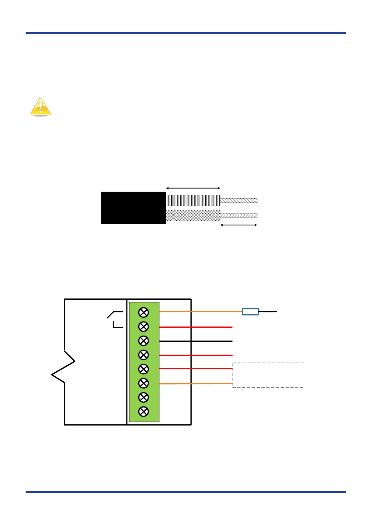
10 - 15mm
6 - 7mm
Conductors
Double
Insulated
Loop 2
Loop 1
S 1
S 2
N
A/L
R1
Load
Active - any phase and/or circuit
See Section 5.2 for override
switch connections
Switched Active
Neutral
Active
Neutral
5. Installation and Wiring Connections
Installing the presence sensor requires a cut-out in the plasterboard ceiling to mount the sensor head and
adequate clearance to fit the control module up through the hole if there is no ceiling space access.
The sensor head connects to the control module using the supplied 5 core cable with pre-terminated connector.
Note: The presence sensor must be installed/connected by a suitably qualified person and it is the
responsibility of the installer to ensure it is completed in accordance with local wiring regulations.
5.1. Control Module
Using a screwdriver, lever the terminal cover on both sides to remove from the housing. Each of the terminals in
the control module accommodates 2x1.5mm2 or 1x2.5mm2 conductors. Figure 1 details the recommended cable
strip lengths for terminating TPS cable to the control module.
Figure 1 – Conductor strip lengths for control module termination.
The one channel control module has two terminals labelled “Loop”. These terminals have no electrical connection
internally and may be used as spare terminals if required. Figures 2 and 3 detail the electrical connections
required for the one and two channel control modules respectively.
Figure 2 – DGEMSR360P1 electrical connections (ILSCM01-D one channel module).
Diginet Control Systems Pty Ltd Page 5 of 16
 Loading...