

Page 1
®
D
IGIMET
3000
Operator’s Manual – 4C
L. J. Engineering, Inc.
Digimet 3000 Manual - 4C
January 2009
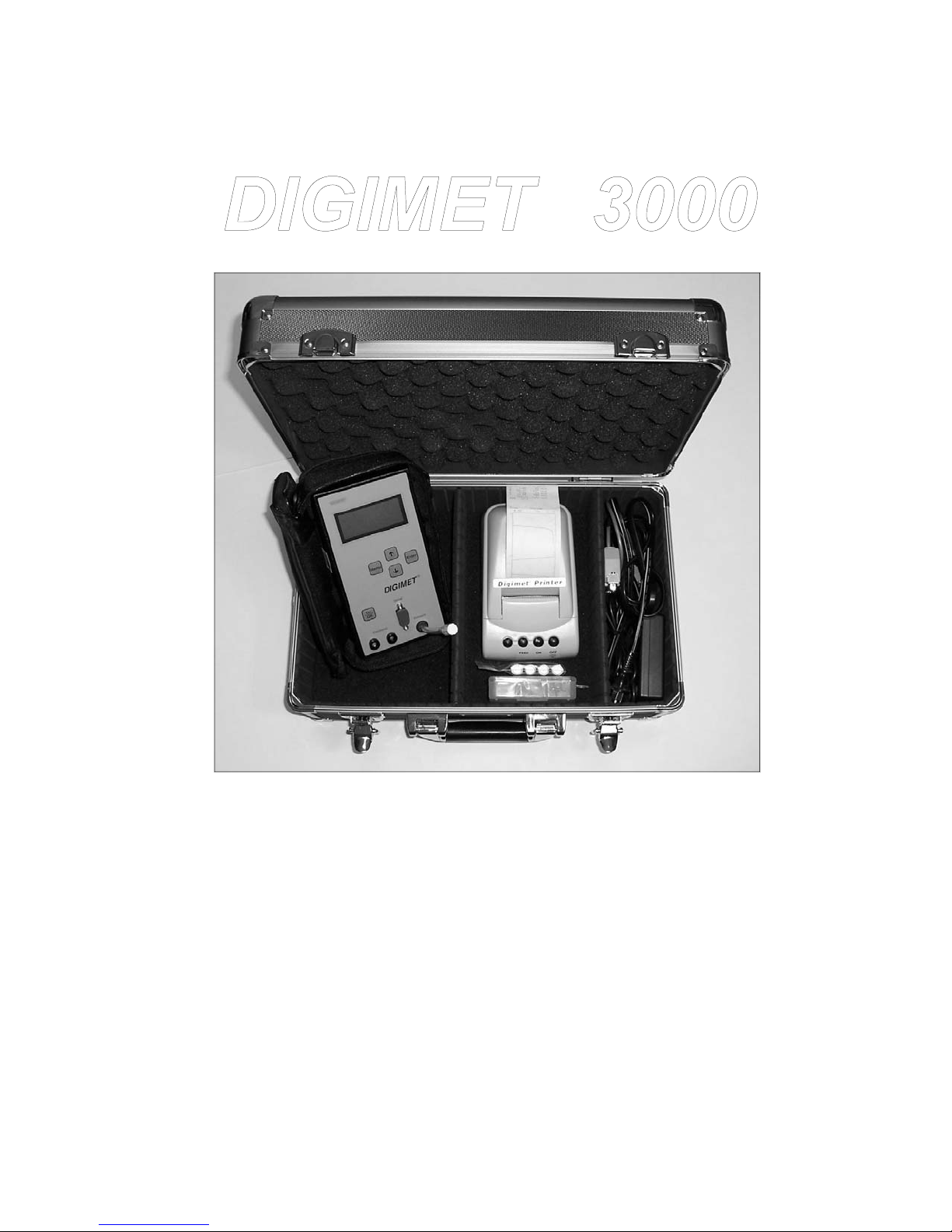
(Digimet 3000 Complete Pictured)
Vacuum and Pulsation Tester
Digimet 3000 Version 4.0
Page 2

Dear Digimet User:
Thank you for your purchase of the Digimet
3000. It's a very good idea to read the
manual before operating any instrument,
such as your new DIGIMET 3000. Please
remember to read the manual thoroughly at
some point for a complete understanding of
the Digimet and its functions.
Thanks, again.
L. J. Engineering, Inc.
2
Page 3

Table of Contents
Table of Contents (cont.)
INTRODUCTION 6
PHYSICAL CHARACTERISTICS 6
Digimet 3000 Enclosure 6
Display 6
Keypad 6
Vacuum Input 6
Electronic Pulsator Input 7
RS-232 Serial Port (9-Pin) 7
Carrying Case 1 – Standard 7
Carrying Case 2 – Large Model 7
Fittings Supplied 8
SPECIFICATIONS 8
Power 8
Vacuum Input 8
Electronic Pulsation Input 9
Resolution and Accuracy 9
Calibration 9
FUNCTION 9
Auto Shutoff 10
Battery Low Indication 10
Figure A - Menu Navigation 14
Auto Zeroing 15
MENU & DISPLAY SYSTEM 16
Navigation 16
Display Standards 16
Battery Low Indication 16
Start-up Display 17
Function Menu 17
UTILITY MENU 17
Upload/Print all Data 18
Upload Graphic Data 18
Print Graph 20
Fluctuation Time Frame 20
Liner Collapse Point (LCP) 20
Display Units 20
Type of Pulsation Storage 20
Auto Shutoff 21
Clear Storage Memory 21
Print Limping data 21
Reset 10
Data Display Hold 10
Store/Recall 11
Store 11
Store Graph 12
Recall 12
Print/Upload 13
Limping data 13
Timer Stamp 15
Labeling 15
DISPLAYS 21
Vacuum Level Function Display 21
Pulsator Ratio Function Display 21
Milk/Rest Ratio Function Display 22
Pulsation-Electronic Function Display 22
Option Menu 23
Available options – Figure B 22
Store/Recall Menus 23
Store Graph Menus 24
MEASUREMENT FUNCTIONS 24
Measurement Constants 24
3
Page 4

Table of Contents (cont.)
Table of Contents (cont.)
Display Units 25
Type Pulsation 25
Auto Shutoff 25
Vacuum Level Function 25
Vacuum Fluctuation 26
Pulsator Ratio 26
Setting Pulsator Ratio Limits 26
B-Phase Fluctuation 27
Milk/Rest Ratio 28
Pulsation Electronic 29
CALIBRATION 29
Unit Initialization 29
Auto-Zero 29
HARDWARE SPECIFICATIONS 29
Microprocessor 29
File - New 32
File - Open 32
File - Save As 32
File - Set Printer Font 32
File - Print 33
File - Exit 33
Options - Label Data Set 33
Options - Set Com Port 33
Options - Type Pulsation 33
Options - Graphing 33
Options - Set Pulsator Limits 33
Options - View Pulsator Limits 33
View Grid or Standard 33
View Inches Hg or kPa 33
Power Subsystem 29
Vacuum Sensing 30
Electronic Pulsation Input 30
DIGIMET PRINTER 30
Digimet Printer Settings 30
Digimet Printer Operations 30
SOFTWARE 31
Computer Requirements 31
DOS program Upload.exe 31
WINDOWS program DigiData.exe 31
Upload Item 32
Viewing Data 32
Notes 32
MENU: 32
Graph Settings 34
Help 34
Upload item 34
Upload all 35
Upload Graph 35
Display Graph 36
Send to D. Printer (Not Used) 36
Rec. archive data (Not Used) 36
Graph data 36
Saving Files 36
When is Uploading complete? 37
Use of other programs 37
CABLES 37
PARTS LIST 37
4
Page 5

Table of Contents (cont.)
MISCELLANEOUS 38
Tapping Holes 38
Comparing Electronic and Pneumatic
Pulsation
Cleaning 38
Use of Stainless Needle 39
Serial Number 39
Configurations 39
Packing List 39
Trademarks 40
Troubleshooting 40
Default Pulsator Ratio parameter Limits 40
ADDENDUM #1 40B
Viewing pulsator data 40B
Using kPa 40B
Pulsator limits not transferred 40B
Setting Pulsator Limits 40B
Testing data on CD 40B
Contents of CD 40B
38
Graphs & Printouts 41
Graphs - computer 47
Quick Reference Guide 48
Digimet Printer Instructions (Digimet Complete) 49
Limited Warranty 50
Contact Information 51
5
Page 6

INTRODUCTION
The Digimet 3000 is a 5-key, hand-held,
battery operated, microprocessor-based
vacuum and pulsation multi-function
testing meter for measuring vacuum level
characteristics and pulsation attributes in a
milking system. The Digimet 3000’s stored
data can be either viewed on its LCD
screen, uploaded to a computer or printed
to the Digimet®Printer.
The Digimet 3000 stores and displays the
following types of information:
• Average Vacuum level
• Maximum Vacuum level until reset by
user
• Minimum Vacuum level until reset by
user
• Fluctuation level with user-set time
frames
• Pulsation ratio with A, B, C and D
phases in percentages and milliseconds
• Evaluation of the B phase - B Fluc
• Maximum and Minimum vacuum per
pulse
• Pulses per minute
• Pulsation Limits can be set for various
pulsation attributes.
• In the Pulsator Ratio Function when
limits are not met or exceeded the value
will blink.
• Unit calculates the Limping Ratio
• Milk/Rest ratio with user-selected Liner
Collapse Point
• Electrical pulsation with On versus Off
time, Maximum & Minimum voltage per
pulse, PPM
• Units measured may be Inches Hg
mercury or kilopascals (kPa)
• Data items can be labeled
• Up to five 10-second graphs can be
saved and later printed or downloaded.
Graphs can be printed to the Digimet
Printer or uploaded to a computer.
• Pulsator data can be stored as single or
dual pulsation.
• User set auto shut-off
PHYSICAL CHARACTERISTICS
Digimet 3000 Enclosure
The Digimet 3000 is enclosed in a durable
black ABS plastic case with dimensions of:
7.50” in length x 4.00” in width x 1.26” in
depth.
Display
The Digimet 3000 has a 16-character by 4row LCD dot-matrix display capable of
displaying the alphanumeric character set
plus additional characters (#, etc.). The
display supports the character attribute of
blinking. The front panel includes a
protective clear window to cover the
display.
Keypad
The Digimet 3000 has a front panel
consisting of a durable and washable
plastic face and integrated membrane key
switches, with access for all input
receptacles. The front panel incorporates
the following membrane keys:
ON
OFF
Menu
Enter
The specific functions of these keys are
described in the section titled: MENU &
DISPLAY SYSTEM.
Vacuum Input
The Digimet 3000 has a 1/8” tube
receptacle located on the front panel for
attachment to an external vacuum source,
vacuum line, etc. The vacuum input will
not be damaged by the intrusion of
6
Page 7

moisture or liquids, but care should be
taken to prevent this from happening.
If, for example, milk were allowed to
enter the transducer and dry, the
performance of the transducer could be
affected. A filter is provided to keep liquids
from coming into contact with the
transducer. IMPORTANT: THE FILTER
MUST BE USED AT ALL TIMES.
If milk accidentally enters the transducer
area, the transducer should be rinsed with
water. Please refer to the section
Cleaning for further instructions. If milk is
allowed to dry inside the transducer, the
transducer will need to be replaced.
The Acrodisc filter will not allow milk to
pass through it. As long as milk is not
allowed to sit in the filter, milk will not
adhere to the filter membrane. Keeping the
filter clean will allow for repeated use.
Check the filter periodically to determine
whether it has become plugged or
restricted. To do this, check Digimet 3000
readings on one of the pulsation (vacuum)
Functions with and without the filter in
place. If similar readings are obtained then
the filter is not plugged.
The tube that comes out of the Digimet
3000 at the port labeled VACUUM is
connected to a quick-disconnect male
fitting (DM3-16-03). When the Digimet is
not in use, a white plug (DM3-16-06) plugs
the opening of the male fitting. When in
use, attach the Acrodisc filter (DM3-15) to
the male fitting and TIGHTEN. Attach to
the Acrodisc filter a 4’ length of 5/32”
plastic tubing which is used to connect the
Digimet 3000 to the vacuum system. Note:
the 5/32” tubing has a small tube clamp on
the end that connects to the Acrodisc. This
provides for a tighter fit to the smaller 1/8”
slip-fit end of the Acrodisc.
Three methods can be used to connect the
tubing to the vacuum system: 1) A needle
connector and stainless steel needle. Be
sure needle does not become plugged
during use. (See the section Use of
stainless needle.) 2. A “T” fitting is
supplied to accommodate plugging into
the short pulsation air tube without use of
a needle. 3) A 1/4” plastic pipe fitting with
a 5/32” nipple is also provided to tap into
plastic pipe systems, as well as a plastic
pipe plug to be used when the fitting is
Electronic Pulsator Input
The DIGIMET 3000 has two banana jack
receptacles located on the front panel.
These jacks are located side-by-side with
a distance between them that
accommodates a standard 3/4" double
banana plug or single plugs as provided
with the unit. THE UNIT WILL FUNCTION
PROPERLY WITH EITHER POLARITY
OF INPUT.
RS-232 Serial Port (9-Pin)
This 9-pin serial connector is used to
connect the Digimet 3000 to either the
Digimet Printer or a computer. Cables are
provided. The serial port has a small
plastic dust cover for protection. This port
is labeled Serial.
Carrying Case – Standard
The DIGIMET 3000 padded canvas
carrying case is approximately 9" long x 5"
wide x 3 1/2" deep. Case includes a
compartment for the DIGIMET 3000 with
two inside straps to keep the unit in place,
and an additional compartment for storing
items such as vacuum tubing, banana
plugs, extra batteries, etc. A shoulder strap
is also provided.
Large Carrying Case
The Large Hard Carrying Case is
approximately 15-3/4” x 9-7/8” x 6-7/8”. It
is divided into compartments which
7
Page 8

accommodate the Digimet 3000, the
Digimet Printer, AC wall transformer (for
the printer) and accessories. A shoulder
strap is also provided.
Fittings Supplied with DIGIMET 3000
The Digimet can accommodate two types
of input: 1) vacuum; 2) electrical
pulsation. Fittings are supplied to facilitate
both forms of input.
Vacuum Port – The vacuum port is labeled
VACUUM and consists of a quickdisconnect male luer fitting (DM3-16-03)
with a white plug (DM3-16-06) attached.
The white plug serves as prevention
against debris entering the vacuum port
when the unit is not in use. A quick
counter-clockwise turn will remove the
white plug from the male luer fitting.
During operation, the vacuum port with its
male luer fitting is attached to an Acrodisc
filter (DM3-15) which is connected to
approximately 4' of 5/32" tubing. A small
hose clamp is provided to secure the hose
to the Acrodisc filter, tightly. Note: the
Acrodisc filters should be used at all
times. To connect the free end of the
tubing to the vacuum system, the user has
several choices: 1) A needle connector
(DM3-Connector) is provided for use with
the stainless needle (DM3-17), which is
inserted into rubber components of the
milking system. (See section
Miscellaneous-Use of stainless needle.)
2) 5/32" nipples may be fitted into the
vacuum system for connecting the 5/32"
tubing. A sample of such a fitting is
provided with your Digimet 3000 (pipe
fitting DM3-PIPE and plug DM3-17-02).
The pipe fitting is a 5/32-27 NPT fitting.
See the section, Tapping holes, for
instructions on tapping holes for this fitting.
3) A pulsator tube adapter “T” fitting
(provided) can be used to check pulsation
line vacuum instead of using the stainless
needle. Connect opposing sides of the “T”
fitting to the short pulsation air tube at the
milk claw and the middle of the “T” to the
Digimet 3000 plastic tubing.
SPECIFICATIONS
This section defines the operating
conditions and performance specifications
which apply to the Digimet 3000.
Power
The Digimet 3000 operates on four AA
alkaline batteries. The Digimet 3000 will
operate for approximately 40 hours before
batteries need to be changed. When the
batteries are low, in the upper right-hand
corner, a “B” will blink, indicating low
battery level. The unit will still function but
the batteries should be replaced. If the
batteries are not supplying sufficient power
for the unit to function properly then the
screen will go blank and the unit will turn
itself off. The battery compartment is
located just behind the LCD display with
the opening on the back side of the unit.
Care should be taken to install batteries
in the proper direction. Data stored in
the Digimet is not affected by turning the
unit off. If the batteries are replaced,
however, they should be replaced within
an hour of removal or storage data will
be lost.
Vacuum Input
In this manual, VACUUM refers to a
differential pressure, with atmospheric
pressure as the reference. Zero vacuum
equates to a zero difference from
atmospheric pressure. Positively
increasing vacuum equates to a
decreasing of pressure relative to
atmospheric pressure (i.e. less than
atmospheric pressure).
8
Page 9

The Digimet 3000 will accept a vacuum
input with the following characteristics:
Range —
Frequency —
equivalent to .5-2 Hz
0-18” Hg, equivalent to 0-60.9 kPa
30 -120 Pulses Per Minute,
Electronic Pulsation Input
The Digimet 3000 will accept an oscillating
electrical input from 0 volts to +/- 30 DC
volts. Over-voltage protection is provided
for inputs up to 50 DC volts so that the unit
will not be damaged. The electrical input
accommodates up to 40 amps. The
polarity of the input signal is rectified to
guarantee that all voltages are positive. An
internal filter is incorporated to eliminate
sharp voltage spikes that occur during
solenoid switching. DO NOT TOUCH
CONNECTORS TO 110-VOLTS OR 220VOLT AC INPUTS.
Resolution and Accuracy
Vacuum Display and Unit Relationships
All vacuum (pressure) measurements will
be displayed according to the selected
Vacuum Display Unit. The available units
are Inches of Mercury (“Hg) and
kilopascals (kPa).
The following provides an orientation to
the equivalency of various pressure units:
1 atm ≈ 30.0” Hg ≈ 14.7 psi ≈ 101 kPa
The actual conversion factor used is:
1” Hg = 3.3864 kPa
The following resolutions are used:
Units Precision Display Range Example
“Hg 100ths 18.00 12.05
kPa 10ths 60.9 45.5
The performance specifications for the
various measurement types are defined in
Measurement
Vacuum
Vacuum
Time
PPM
Ratio
Voltage
Units Resolution Accuracy
“Hg 0.01 +/-.06
kPa 0.1 +-.2
msec 1 +-1
ppm 0.1 +-.1
% 0.1 +-.1
DC Volts .1 +-.3
the table below. Specifications are for the
entire operating range of the Digimet
3000, and for a temperature range of 32150 degrees Fahrenheit.
Calibration
The Digimet 3000 is factory calibrated. Its
components are designed so that losing
calibration is unlikely, but if the unit is
subjected to harsh environments or
treated roughly, it may need factory
recalibration at some future time. But, as
any electronic instrument, yearly
recalibration is recommended.
FUNCTION
This section describes the operation and
features of the Digimet 3000.
The functions of the Digimet 3000 are
divided into the following areas:
System Functions
Auto Shutoff
Battery Low Indication
Reset
Data Display Hold
Store/Recall
Store Graph
Print/Upload
Limping data
Timer Stamp
Labeling
Auto Zeroing
9
Page 10

Menu & Display System
Measurement Functions
Vacuum Level
Pulsator Ratio
M/R Ratio
Pulsation Electronic
Utilities
Upload/Print all data
Upload Graph
Print Graph
Fluctuation Time Frame
Liner Collapse Point
Type of Pulsation Storage
Display Units - “ Hg or kPa
Type Pulsation - Dual/Single
Auto Shutoff
Clear Storage Memory
Print Limping Data
Set Pulsator Limits
The measurement Functions are fully
independent from one another. Information
(unless it is “stored”) is not retained when
switching from one Function mode to
another.
Auto Shutoff
The Digimet 3000 provides for automatic
shutoff of the unit after a user selectable
period of time from 0 to 30 minutes of nonuse. This is set in the Utility Menu, item
number eight. See section on Utility
Menu. This feature is designed to
maximize battery life. “Use” of the unit is
defined as presses on the front panel
keys. Each depression of a key will cause
an internal timer to reset to zero. This
timer is continually counting, and when it
reaches the specified time, the Digimet
3000 will shut off. When the Digimet 3000
is auto-shutoff, all currently displayed
information will be lost, the same as if a
user had switched the unit off. (Stored
data is not lost.) When the unit is autoshutoff and subsequently turned back on,
it will perform the normal start-up
sequence defined in the section entitled
Start-up Display.
Battery Low Indication
The Digimet 3000 detects when the
battery power is low and displays a
message. The Low Battery indicator is a
blinking “B” in upper right corner of the
screen. See more about the Battery Low
Indication under heading MENU &
DISPLAY SYSTEM.
Reset
The Vacuum Level Measurement function
has the ability to “reset” the Max. and Min.
Vacuum readings. Vacuum Level Min/Max
Reset is further discussed in the section
entitled Vacuum Level Function.
Data Display Hold
The Digimet 3000 has the capability to
“freeze” the data currently displayed, with
the use of the Hold mode. The entire set of
measurements for a Function that is held
will be frozen, including items not visible
within the display window. This allows the
user to scroll through all measurements.
When placed in Hold mode, the Digimet
3000 will continue to sample input and
calculate the measurements for the current
function; however, the display will not be
updated with the current information, but
will display the measurements at the time
the unit was placed in Hold mode. When
accessing the Option Menu to utilize Hold,
within a particular Function, the MENU key
must be pressed. The data that is on the
screen the instant the Menu key is pressed
will be the data held.
When the Digimet 3000 is then placed in
the Continue mode, the display will be
updated with current measurements. This
operation is analogous to a split-time
feature of a stopwatch. The Hold mode is
automatically released when the
measurement Function is exited. For
example, if the unit is in Hold mode within
10
Page 11

the Vacuum Level measurement Function
and then the Pulsator Ratio Function is
selected, the Pulsator Ratio function will
begin in the Continue mode.
All measurement Functions have the Hold
mode capability.
Store/Recall
The Store/Recall function allows for the
storage of screen data within the Digimet
3000’s memory, and for the recall to the
Digimet display, printing to the Digimet
Printer or uploading to a computer.
Store
The Store function of the Digimet 3000
allows a measurement set to be stored for
later viewing (recall) or uploading (to a
computer) or printing (to the Digimet
Printer). A measurement set contains all
measurement parameters of the Function
being stored plus a label of up to 16
characters or if no label is inputted a timerstamp will be associated with the data.
This data is stored into dedicated storage
slots (selected by the user) and remains in
storage even if the unit is turned off and
back on.
Each measurement Function contains a
maximum number of measurement sets
that can be stored, and each slot is
numbered. This means that storage space
reserved for a particular Function cannot
be used by any other Function.
The following storage is provided:
Measurement
# Storage Slots
Vacuum Level 10
Pulsator Ratio 60
M/R Ratio 30
Pulsation Electronic 5
Graph Storage 5
Some measurements require a minimum
start-up time before data is displayed (see
section titled MEASUREMENT
FUNCTIONS). This is generally
approximately two or three seconds,
depending on the measurement. If the
required start-up time has not elapsed, the
Store option will not be available, it is
surrounded by < > on the display screen.
If the unit is in the Hold mode the held data
will be stored. Otherwise, the data that is
current at the time Store is selected will be
stored.
When the Store screen appears, choose the
storage slot number where the data is to be
stored. An empty slot has neither a timerstamp or a label next to it. The next screen
will allow a label to be attached to the item
being stored. The top of the screen will
indicate “Label Slot 01”. The 01 would
change depending on the number of the slot.
Below this, there will be 16 hyphens
indicating 16 available characters for the
label. The cursor will be all the way to the left
under the first character. Choose characters
for the label by using the up and down arrow
key on the keypad. The up arrow key will
start with A,B,C,D and so on through some
symbols and numbers. The down arrow key
starts with the (space),#,0,1,2 and so on.
Once the character is chosen, press the
Enter key to advance to the next character.
When done with the label press the Menu
key to Save. If the Menu key is pressed
without selecting any characters for a label, a
timer stamp will be associated with the data
stored. This timer-stamp is described in the
section Timer-Stamp. Once the item is
saved, the Option Menu will re-appear.
Store Graph
This option appears in all three of the
pneumatic functions in the Function Option
Menus. The time period for graph length is
11
Page 12

set at this time from 2 seconds to 10
seconds. Up to five separate graphs from
2 seconds to 10 seconds each, can be
stored. On subsequent store graphs the
unit will remember storage time and will
not need to be changed unless you desire
a different time period. Please note: It is a
good practice to match the fluctuation time
frame - a variable in the Vacuum Level
Function (set in the Utility Menu), with the
store graph time period so the numeric
data printed out on the graphs, matches
the activity of the graph. For example, you
would want to set the Fluctuation Time
Frame to 3 seconds (Utility Menu item #4)
if you wanted a graph period of 3 seconds.
This practice is only applicable for the
Vacuum Level Function. The Fluctuation
Time Frame is not a variable in the other
pulsation functions. Another note
regarding Fluctuation Time Frame and
Graphing time: If the Fluctuation Time
Frame is less than the Graph time, then
the Fluctuation figure, which will print-out
on the graph, will cover the last portion of
the graph which includes the period of the
Fluctuation Time Frame. For example, if
the Fluctuation Time Frame is 2 seconds
and the Graph time is 3 seconds then the
Fluctuation figure will be for the last 2
seconds of the 3 second graph. If the
Fluctuation Time Frame is greater
than
the Graph time, then the Fluctuation figure
will be for the time period of the graph. For
example, if the Fluctuation Time Frame is
set for 5 seconds and the Graph time is for
3 seconds, the Fluctuation figure will be for
3 seconds.
When you first enter Store Graph, a
screen will appear with 5 storage slots.
After choosing the slot the next screen will
allow a label. It is not necessary to choose
a label. In the case where no label is
chosen the graph will have a timer stamp
associated with it. When the label screen
is exited, the screen will indicate, Enter for
3 sec. of graph. Up/Down changes.
Menu to exit. (This assumes that 3
seconds is the chosen graph period). Time
can be set from 2 seconds to 10 seconds.
Pressing the appropriate key will either exit
without saving or you will enter the
function in the Recording Mode. In this
mode an R will appear in the upper right
corner of the Digimet screen. There is a
short delay before the unit begins Storing
the graph. When the R begins to blink,
storing data has begun. The initial delay
allows the readings to stabilize. Note: If
you want to capture a particular
activity, start the activity the moment
the “R” starts to blink.
After the R stops blinking, storage is
complete. You can now use Print Graph
to graph to the Digimet Printer or use
Upload Graphic Data to upload graph
data to the computer for viewing on the
Computer Screen. Upload Graphic Data
and Print Graph are both options that
appear in the Utility Menu, item 2 and 3.
The reason for these different options is
because the Digimet formats the data
differently depending on the ultimate way
that the data will be viewed.
Recall
Data that has been previously stored may
be recalled for display by the Digimet
3000. The particular measurement set that
will be recalled depends on the current
12
Page 13

measurement Function. That is, the
Digimet must be in a measurement
Function for this option to be available. If a
slot does not contain any stored data, the
Digimet will not allow selection of that slot
for recall.
When the RECALL screen appears, if
there is stored data in a particular slot,
there will be either a label or a timer-stamp
next to the numbered slot. Only twelve
characters of the label will appear in the
Store screen.
When data is recalled, it is displayed on
the Digimet 3000 display in the same
format as during normal sampling
operation, except that the recall slot
number appears (blinking) at the upper
right corner of the display screen. Both
recalled data and held data can be stored
in multiple slots, allowing the user to “make
a copy”.
Print/Upload
The Print/Upload function allows the user
to Print an individual item to the Digimet
Printer or Upload an individual item to a
computer via a serial port. In order to print,
the Digimet Printer must be connected to
the Digimet 3000 (See section on the
Digimet Printer). The printer cable
supplied with the Digimet Printer has a 25pin male serial connector at one end and a
9-pin male serial connector at the other.
The 9-pin end connects to the Digimet
3000 and the 25-pin end connects to the
Digimet Printer. The next step is to supply
the Digimet Printer with power using the
supplied AC wall transformer. Turn the
Digimet Printer “ON”. Press the Enter key
to select Print/Upload. A screen will appear
with storage slots identified along with
either labels or timer-stamps (same as in
Recall). Choose the item to Print/Upload
by selecting the item with the up and down
arrow keys. Select the item by pressing
the Enter key. The next screen will indicate
that the numbered slot with the attached
label will be sent. Press Enter to send,
Menu key to exit without printing or
uploading the item. If there is a loose cable
connection or the Digimet Printer is not
“ON” then an error message “No Clear to
Send” will appear and remain on the
screen. If the “No Clear to Send” remains
on the screen, then press the Menu key to
exit and the connection problem must be
corrected. If all is OK then the item data
will be sent to the Digimet Printer.
The above procedure would be identical
for Uploading an item to the computer
accept for a few differences. To upload,
the supplied 6’ computer cable (supplied
with the Basic Digimet 3000) which has 9pin connectors at each end, one is a
female and one is a male connector, must
be used. The male end attaches to the
Digimet 3000 and the other to the
computer. The second difference would be
that the software to upload data from the
Digimet 3000 must be loaded and running
on a computer to complete the upload
procedure. Other than these two
differences the steps for Uploading would
be the same as for Printing. For
information on the software requirements
for uploading data from the Digimet to a
computer, see the section on
SOFTWARE.
Limping data
In versions greater than 3.2, a feature was
added to the Pulsator Ratio Function
called the Limping data.
The difference in the milking ratio of the
right and left sides of the pulsator is
referred to as “limping ratio”. Limping may
be caused by plugged or worn small air
tubes, plugged or leaking pulsator tubing,
13
Page 14
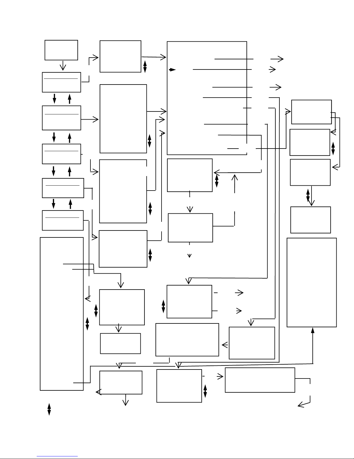
Figure A - Menu Navigation
Start-up
Screen
FUNCTION MENU
Vacuum Level
FUNCTION MENU
Pulsator Ratio
FUNCTION MENU
M/R Ratio
FUNCTION MENU
Pulsation Electronic
FUNCTION MENU
Utility Menu
-UTILITY MENU
1Upload-Print all
Data
2 Upload Graphic
Data
3 Print Graph
4 Fluc. Time
Frame >1 2 3 4
5 10 sec
5 Liner Collapse
Point Equals
LCP= 6.5 “Hg
6 Type Pulsation
>Dual
Single
7 Units
>Inches Hg
kPa
8 Auto Shutoff
30 minutes
9 Clear
Storage
Memory
10 Print limping
data
11 Set Pulsator
Limits
Menu to
Exit
* Use Up & Down
Arrow Keys
VACUUM LEVEL
Ave 0.00 “Hg
Max 0.00 “Hg
Min 0.00 “Hg
Enter*
Enter
Enter
Fluc 0.00 / 1s
PULSATOR RATIO
A+B 60.2% 699ms
C+D 39.8% 463ms
B Fluc 0.43”Hg
Max/P 10.63”Hg
Min/P 0.00”Hg
A 5.3% 61 ms
B 54.9% 638 ms
C 5.7% 66 ms
D 34.1% 397
ms
Total 1162
Enter
M/R RATIO
Ratio 63:37
PPM 54.2
Max/P 13.59 “Hg
Min/P 0.02 “Hg
Milk 63.3 %
Milk 701 ms
Rest 36.7 %
Rest 405 ms
LCP 6.50 “Hg
TTime 1106
PULSATION ELEC 01
On 60.4%
Off 39.6%
Max/P 10.2 Volts
Min/P 0.0 Volts
PPM 60.4
Enter
GRAPH
09:06:14
> M01 BARN #2
V02 MILK TR
P03 08:12:15
Press Enter to
start graphing
Menu to exit.
Enter for 3
sec. of graph
Up/Down changes.
Menu to exit.
Enter
Back to function in record mode
Menu
Menu
Menu
-OPTION MENU
*
Menu
Menu
Function Menu
Hold
Reset (Only for Vacuum Level
Function)
Store
Store Graph (not for Pulsation
Electronic)
Recall
Print/Upload
Limping data (Only for
Pulsator Ratio Function)
PRINT 09:06:14
> 01 BARN #1
02 MILK TRAP
03 08:12:00
Enter
Send Slot 01
BARN #1
Enter to send
Menu to exit.
Enter
To Printer or
Computer then back
to Option Menu
RECALL 09:06:14
> 01 BARN #1
02 MILK TRAP
03 08:12:00
Label Graph 01
_ _ _ _ _ _ _ _ _ _ _ _ _ _ _
Menu to Save.
STORE 09:06:14
01 BARN #1
02 MILK TRAP
03 08:12:00
> 04
Enter
Enter
Enter
Enter
Enter
Enter
Enter
Enter
Enter
Menu - back to
Option Menu
Back to
Menu
Enter
Option
Menu
Back to
Function
GRAPH 01:16:58
> 01 BARN
02 MILK
03
Label Slot 09
_ _ _ _ _ _ _ _ _ _ _ _ _ _ _ _
Menu to Save.
(Enter to move cursor)
Save then To
Option Menu
Back to
Function
Menu
Back to
Function in Hold
Back to
Function
LIMPING
> View one
item
LIMPING
> 01AB Available
02AB Not Avail.
03AB Not Avail.
LIMPING
01AB Limping
0.2 %
1 msec
LIMPING
02AB Not Avail.
(press the down arrow
key for more items)
Set Limits:
Bfluct Max 0-3.00
MaxHiV/Pls 5.5-
16.00
MinHiV/Pls 5.0-15.50
MinVac/Pls 0-4.00
MaxAPhase 20-300
MinAPhase 20-300
MaxBPhase 100-750
MinBPhase 100-750
MaxCPhase 20-500
MinCPhase 20-500
MaxDPhase 100-500
MinDPhase 100-500
Max PPM 20-198
Menu
14
Page 15

as well as the pulsator itself.
When using the Digimet 3000 in the Dual
Storage Mode, pulsator data is stored in
slots labeled 01A, 01B, 02A, 02B ... 30A,
30B. When both the A and B slots are
filled with pulsator data, the Digimet will
calculate the Limping data. The Limping
data is an item which appears in the
Option Menu of the Pulsator Ratio
Function. The Limping data will appear as
a percentage and in milliseconds.
The Digimet 3000 evaluates the A + B
phase of each side of the pulsator and
indicates the difference as a percentage
and in milliseconds. For example, Limping
data would appear as follows:
07AB Limping
0.1 %
2 msec.
The Limping data can be viewed on the
Digimet’s display, printed to the Digimet
Printer or uploaded to a computer for
viewing and/or printing. The printing of
Limping data from the computer is
available on the DigiData program version
3.4 and greater.
Timer Stamp
In conjunction with the Store/Recall
function, a clocking mechanism is built in.
The purpose of this clocking mechanism is
to provide an internal real-time counter
that is used to timer-stamp the stored
measurement data. Unless a label is
chosen the timer-stamp will appear in the
Store, Store Graph, Recall, Print/Upload,
Upload Graph and Print Graph screens.
When an item is printed or uploaded the
timer-stamp in addition to the label, if
chosen, will appear. The clock will
increment every second with a range of
12:00 hours. Thus when the clock reaches
11:59, the next increment will roll the clock
over to 00:00.
Labeling
When storing data or graphs, prior to
storage but after choosing the storage slot,
a screen will appear giving you the
opportunity to label your stored item. You
can use up to 16 characters. Use the up
and down arrows to choose the character/
number/symbol. Press the Enter key to
advance to the next character. Holding the
arrow keys down for more than two
seconds will advance the characters
automatically. When done with your label
pressing the Menu key will exit and save
your data or graph. Exiting, with the Menu
key, without entering labeling will attach a
timer stamp to your data. So, it is not
mandatory to choose a label.
Auto Zeroing
The Digimet 3000 has an auto-zero
capability. Due to temperature variations
which can affect certain components, the
Digimet 3000 is designed to auto zero.
This takes place any time the Digimet is in
the Vacuum Level Function or one of the
pulsation (vacuum) Functions with NO
VACUUM INPUT applied. At this time, the
Digimet displays all zeros for Avg Vac,
Max Vac, Min Vac, and Fluctuation. (Note:
If the unit has just displayed vacuum
readings, it may be necessary to reset
Max Vac before a zero reading is
obtained.) The Pulsation (vacuum)
Functions will appear blank when autozeroed.
Therefore, the following procedure is
recommended: When taking Vacuum
Level of pulsation (vacuum) Function
measurements, periodically take a
reading with no vacuum input to allow
the Digimet 3000 to auto-zero.
15
Page 16

MENU & DISPLAY SYSTEM
The menu system is navigated via the
front panel keys. The basic menu/function
structure is depicted in Figure A on Page
14. The structure and operation of the
menu/display are designed to provide
easy access to all of the Digimet 3000
features.
The use of the keys is as follows:
These keys are used to scroll the screen.
For menus, these keys are also used to
change the current selection. Once the
bottom of a screen has been reached (or
the last item selected), subsequent
pressing of the down arrow will have no
effect, that is, the screen will not loop back
to the top. Similarly, pressing the up arrow
will have no effect after the top of the
screen is reached. The arrow keys are
also used to change data in the Utility
Menu and to choose letters or characters
for labels. Both to be described in a later
section.
Enter
The Enter key is used to make a selection
or a change of some kind. This could be
changing to a new Function, changing a
system parameter, etc. But this key is
always associated with some effect on the
Digimet system.
Menu
The Menu key is used to access menus.
The Digimet utilizes "pop-up" menus which
are easily accessed with the Menu key.
Navigation
Navigation through the Digimet menus and
functions is illustrated in Figure A page 14.
Display Standards
The design of the display system follows
some basic standards in order to provide a
consistent user interface.
The top line will always display a title in
capital letters, indicating the purpose of the
current screen. This will either be the name
of a menu or the name of a measurement
Function. This title line does not scroll.
Hold Indicator: For all measurement
Function displays, the top right two character
spaces are designated for indicating that the
unit is in Hold mode. Hold mode is signified
by the presence of a single, blinking
character "H". Sampling or real-time mode
is indicated by the absence of the character
"H".
Recall Indicator: The same two character
spaces (top right) are reserved to indicate
the number of a recalled set of
measurements. The recall function is
described in section titled Store/Recall.
Battery Low Indication
A low battery, as detected by system
circuitry, will be indicated on the display by a
blinking "B" in the display status area (upper
right corner).
The battery low indication (blinking "B") on
the display means the batteries will soon
16
Page 17

expire, causing the unit to cease
functioning. The unit will operate properly
for several hours after the low battery
indicator appears on the screen.
IMPORTANT: STORED DATA IS NOT
LOST WHEN THE BATTERIES EXPIRE
OR ARE REMOVED FOR
REPLACEMENT, ASSUMING THAT
FRESH BATTERIES ARE REINSTALLED
WITHIN AN HOUR.
Start-up Display
Each time the Digimet 3000 is turned on,
the following initial screen will be
displayed:
LJE,Inc.
Digimet 3000
Ver 4.0 SN:00001
Copyright 2004
This start-up screen will be displayed for 5
seconds.
The following screen layout diagrams
(shown on the next couple of pages)
illustrate two ways in which a screen is
scrolled. The first is as a "page." A
screen with a page scroll displays lines in
sets of three (excluding the top line which
does not move). These three-line page
groupings are identified by shading. The
second method of scrolling is a single-line
scroll, in which individual lines are scrolled
continuously (rather than in groups as with
the page scroll).
Function Menu
The Function Menu is the system's main
menu. It allows the selection of a
particular measurement Function or of the
Utility Menu.
After the initial Start-up Display, the
-FUNCTION MENU
1 Vacuum Level
Avg Vac,Min&Max
Fluctuation
2 Pulsator Ratio
ABCD% &ms,Min/P
Max/P PPM
3 M/R Ratio
LCP= 6.50
Max/P Min/P PPM
4 Pulsation-Elec
On/Off PPM
Max Volts DC
5 Utility Menu
Settings for
Functions
selection on the Function Menu will default
to the first option. Upon selection of an
option from the Function Menu, and
subsequent return to the Function Menu,
the last-selected item will be the default
selecti
Action of Keys
Menu None
Enter Go to selected measurement
Function or Utility Menu
Up arrow Previous item on Function
Down arrow Next item on Function Menu
UTILITY MENU
The Utility Menu allows the user to change
several Digimet settings which include:
• Upload/Print all data
• Upload Graph
• Print Graph
• Fluctuation Time Frame
• Liner Collapse Point
• Type of Pulsation storage
• Display Units
• Auto Shutoff
• Clear Storage Memory
17
Page 18
-UTILITY MENU
1 Upload-Print all
Data.
2 Upload Graphic
Data.
3 Print Graph
4 Fluc. Time
Frame 1 >2 3 4
5 10 sec
5 Liner Collapse
Point Equals
LCP= 6.5 “Hg
6 Type Pulsation
Dual
>Single
7 Units
>Inches Hg
kPa
8 Auto Shutoff
10 minutes
9 Clear
Storage
Memory
10 Print
Limping data
11 Set Pulsator
• Print Limping data
•
Set Pulsator Limits
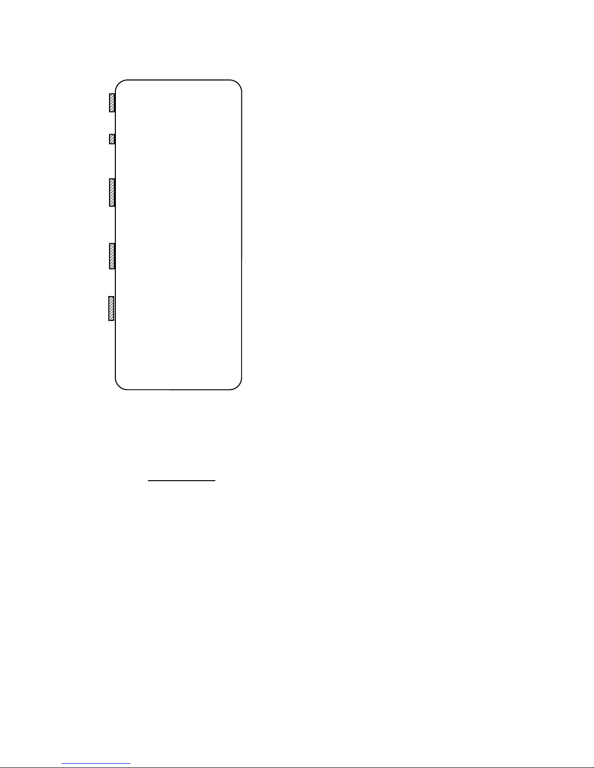
The Utility menu is depicted above:
Action of Keys
Menu Return to Function Menu
Up arrow Previous screen/selection
Down arrow Next screen/selection
Enter Edit the value on the displayed
screen
The > symbol points to the current setting.
The enter key is used to access the
Editing mode, which is indicated by a
blinking "E" in the upper right of the
display. While in Editing mode, the (up
arrow) and (down arrow) keys function to
change the current value. Edit mode may
be exited by either pressing the Enter key
to save any changes, or pressing Menu to
abandon any changes that have been
made in the current setting. The editing of
the various settings is described in the
following paragraphs:
Upload-Print all Data
Pressing the Enter key will initiate
transmission of data to either the Digimet
Printer or a waiting computer. The Digimet
Printer must be on if printing is to take
place otherwise an error “No Clear to Send”
will appear at the bottom of the screen. If
transmission is to a computer then the
receiving program must be up and running.
If not or there is a poor cable connection
between the Digimet and the computer the
same error will appear, “No Clear to Send”.
To exit without sending data to the printer
or computer press the Menu key. Note: If
you get no response from the printer after
attempting to print or data that was sent
appears garbled, turn the Digimet OFF then
ON. If you are using the Digimet Printer,
unplug it. Sometimes resetting either
device by turning OFF then ON or
unplugging, will solve the problem. Data
once stored in the Digimet is not lost even if
an upload fails. The data is securely stored
in the Digimet Memory. To erase stored
memory you would have to Clear Storage
Memory (ninth item in the Utility Menu) or
leave the unit without batteries for more
than an hour. This command will upload or
print to the Digimet Printer all numeric data.
Graphs must be printed or uploaded
separately. See Upload Graphic Data (Item
2 in the Utility Menu) and Print Graph (Item
3 in the Utility Menu).
Upload Graphic Data
This Utility Menu item is used to upload
graphs from the Digimet to a computer.
These graphs are formatted to be viewed
on the computer screen and, ultimately,
they can be printed to the computer’s
printer. They are not intended to be sent
to the Digimet Printer. However, if the
raw data is desired, as shown below,
18
Page 19

time “Hg
.000 12.00
.008 12.01
.016 12.02
(etc.)
you can Upload Graph Data to the Digimet
Printer. The print-out will include all the
time and vacuum data in numeric form, not
a graph. There are 125 readings made
each second. So, for a two second graph,
the raw data will consist of 250 readings.
After pressing the Enter key, the Graph
storage menu will appear. There are 5
storage slots for graphs. If there are stored
items, the slots will either have a timer
stamp next to the slot number or there will
be a label which would have been put in at
the graphing time. Also, the slot number,
01, 02, 03, 04, or 05 will have either a V for
Vacuum Level, P for Pulsator Ratio or a M
for Milk/Rest Ratio in front of it, to
designate which function the graph
originated from. Once you choose the slot
pressing the Enter key, the next screen will
be “Press Enter to start graphing. Menu
to exit.” At this point, before pressing the
Enter key again, the Digimet 3000 should
be connected to a serial port of a computer
with the 6 foot serial cable provided. The
DOS program or Windows program
provided should be up and running on the
computer in order to accept the uploaded
graph. The following will be the steps to
take utilizing the Windows Program
provided – Digidata. Explanation of
uploading using the DOS program can be
found in the SOFTWARE section.
• Press the Upload Graph button on the
Digidata computer screen, the button
will change to “Press Digi then Here”.
• Press Enter on the Digimet one more
time.
• Press the “Press Digi then Here”
button. Button changes to
“******Uploading.” As uploading is
taking place this button will change to
“*****Still Uploading”. When uploading
is completed the button will say “*Done
Uploading”. The Save Graphic file
window will then appear. Choose a
name for your graph file and be sure it
ends with .dgr.
• Press the OK button in the Save
Graphic files window.
• Your graphic file has been uploaded
from the Digimet and saved as a
computer file.
If, however, the message, “No Clear to
Send” appears and remains, then the
Digimet does not have a good connection
or something is wrong with the hookup. If
this happens, pressing the Menu key will
exit the screen and the connection
problem will have to be solved.
The steps are listed here again for
Uploading graphic data from the Digimet to
the Computer.
1. Connect the 6 foot serial cable to the
Digimet and the computers serial port.
2. Open the Digidata program.
3. Go to the UTILITY MENU item 2
Upload Graphic Data on the Digimet.
4. Press Enter on the Digimet.
5. Choose your Graph to upload on the
Digimet.
6. Press Enter on the Digimet, one time.
7. Press the Upload Graph button on the
Digidata computer screen, the button
will change to “Press Digi then Here”.
8. Press Enter on the Digimet one more
time.
19
Page 20

9. Press the “Press Digi then Here”
button. Button changes to
“******Uploading.” As uploading is
taking place this button will change to
“*****Still Uploading”. When uploading
is completed the button will say “*Done
Uploading”. The Save Graphic file
window will then appear. Choose a
name for your graph file and be sure it
ends with .dgr.
10. Press the OK button in the Save
Graphic files window.
11. Your graphic file has been uploaded
from the Digimet and saved as a
computer file.
Print Graph
This Utility Menu item is used for printing
graphs to the Digimet Printer. These
graphs are only formatted for the Digimet
printer.
Pressing the Enter key will bring up the
Graph storage menu (same menu as in
Upload Graphic Data). Choose the slot to
print.There are 5 storage slots for graphs.
If there are stored items, the slots will
either have a timer stamp next to the slot
number or there will be a label which would
have been put in at the graphing time.
Also, the slot number, 01, 02, 03, 04, or 05
will have either a V for Vacuum Level, P for
Pulsator Ratio or a M for Milk/Rest Ratio in
front of it, to designate which function the
graph originated from. Once you choose
the slot pressing the Enter key, the next
screen will be “Press Enter to start
graphing. Menu to exit.” At this point,
before pressing the Enter key again, the
Digimet 3000 should be connected to the
Digimet Printer and the Digimet Printer
should be on. Pressing Enter again will
initiate the printing of the graph on the
Digimet Printer.
Fluctuation Time Frame
While in Time Frame Edit mode, the up
arrow key will move the marker to the left
and the down arrow key will move the
marker to the right, indicating the selected
setting. Fluctuation time frame can be set
to 1, 2, 3, 4, 5 or 10 seconds. The
Fluctuation time frame establishes the time
frame for the variable - Fluctuation in the
Vacuum Level Function. The Digimet is
looking for the Max and Min value over the
period set here and outputs that difference
to the display and calls it Fluctuation.
Liner Collapse Point (LCP)
While in the LCP Edit mode, the up arrow
and down arrow keys are used to increase
or decrease the liner collapse point.
Prolonged pressing down of the key will
cause rapid advance of the value. LCP
can be set from 0.0 inches Hg/0.0 kPa to
18.0 inches of Hg/60.9 kPa.
Display Units
While in the Display Units Edit mode, the
up arrow and down arrow keys are used to
position the marker next to the desired
setting. Choices for display units are
Inches Hg and kPa.
Type of Pulsation Storage
Storage slots for the pneumatic functions
of Pulsator Ratio and Milk/Rest Ratio can
be either numbered 1,2,3,4, etc. (Single
pulsation) or 1A, 1B, 2B, 2C, etc. (Dual
pulsation). Use the up and down arrow
20
Page 21

keys to move the indicator. To choose that
item, press the Enter key. This item can not
be changed without first clearing storage
memory.
Auto Shut-off
User can set the desired time for the unit to
automatically shut-off for non-use. This time
can be set from 0 to 30 minutes. Press the
Enter key to put the unit into the Edit mode,
then use the arrow keys to select the
desired time.
Pressing the Menu key or Enter key will
take you back to the Function Menu.
Clear Storage Memory
Clear Storage Memory is the last item that
appears in the UTILITY MENU. The Clear
Storage Memory screen contains no Edit
mode. Pressing the Enter key will cause the
screen to change to:
-UTILITY MENU
9 Clear Memory
> No
Yes
The marker will default to NO. To move the
marker to YES, press the down arrow key.
Pressing the arrow keys repeatedly will
move the marker back and forth, from YES
to NO. To choose Clear Memory, move
marker to YES, then press ENTER. If
clearing memory is not desired, move
marker to NO and press ENTER or press
MENU key at any time. Pressing the MENU
key will exit back to the FUNCTION MENU.
IMPORTANT: WHEN CLEARING
MEMORY, ALL MEMORY SLOTS--10 IN
VACUUM FLUCTUATION FUNCTION, 60
IN PULSATOR RATIO FUNCTION, AND 30
IN MILK/REST FUNCTION, 5 IN THE
PULSATION ELECTRONIC AND 5 GRAPH
STORAGE SLOTS--WILL BE ERASED.
21
There is no selective erasure of individual
memory slots.
-UTILITY MENU
10 Print
Limping data
Print Limping data – Limping data can be
printed to the Digimet Printer or uploaded
to a computer by using Utility Menu item
10, Print Limping data.
DISPLAYS
VACUUM LEVEL
Avg 0.00 “Hg
Max 0.00 “Hg
Min 0.00 “Hg
Fluc 0.00 / 1s
Vacuum Level Function Display
The Vacuum Level Function displays
those measurement calculations as
described in the section on the Vacuum
Level Function. The display format is
depicted in the following column:
In addition to the calculated
measurements, the current Fluctuation
Time Frame setting will also be displayed
as " /1s " on the last line, where 1 second
is the current setting.
PULSATOR RATIO
A+B 60.2% 696ms
C+D 39.8% 460ms
B Fluc .33 “Hg
Max/P 13.68“Hg
Min/P 0.00“Hg
A 11.3% 131 ms
B 48.9% 565 ms
C 12.0% 139 ms
D 27.8% 321 ms
Total 1156 ms
Pulsator Ratio Function Display
The Pulsator Ratio Function displays those
Page 22
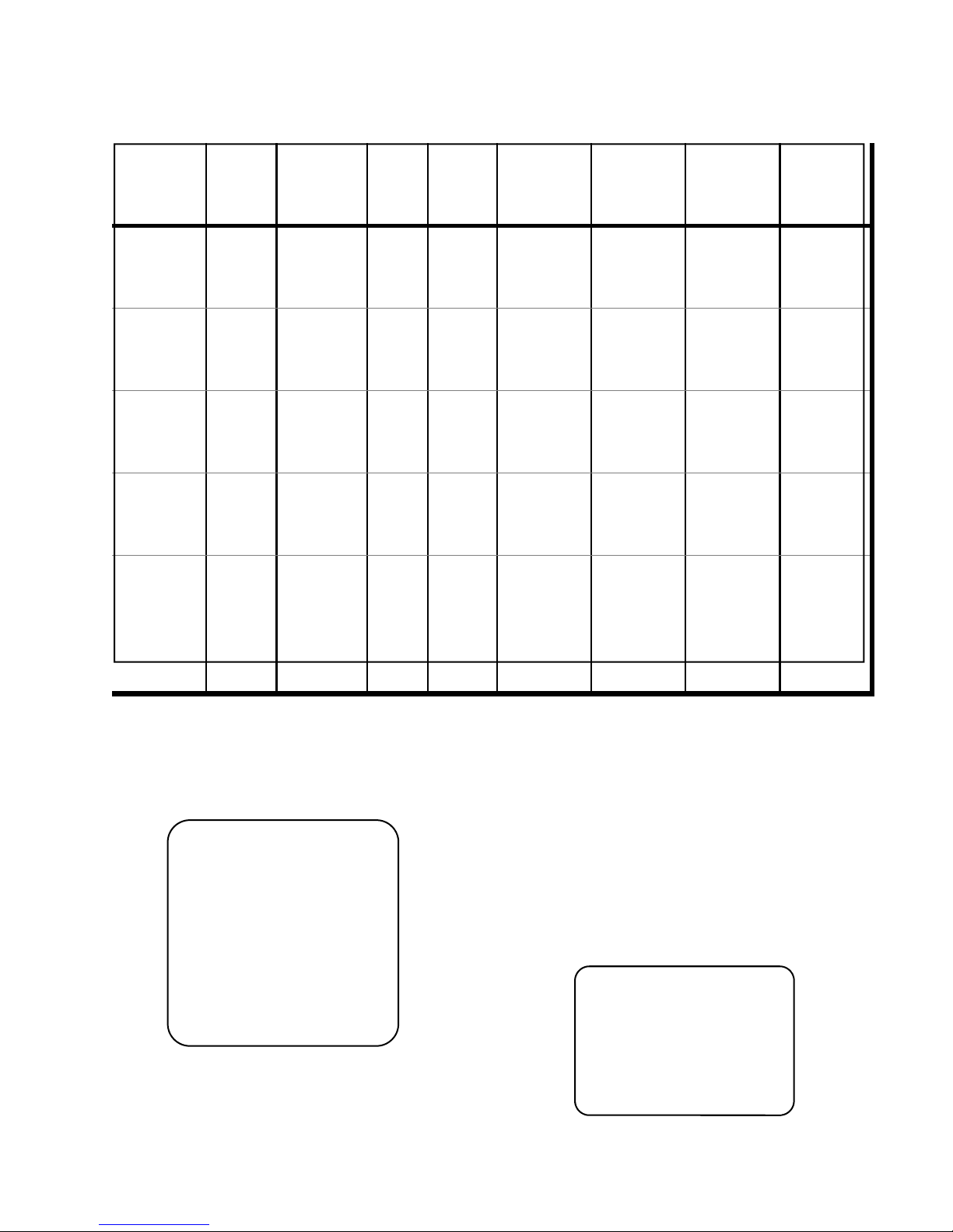
Figure B
Function OPTIONS
Vacuum
Level
Functio
n Menu
X X X X X X X
Hold/Cont. Reset Store Store
Pulsation
Ratio
M/R Ratio X X
Pulsation
Electronic
Display
after
selecting
Enter
Go to
Functio
n Menu
X X
X X
Return to
Measuremen
t Function
- Hold or
Continue
Return
to
Measure
ment
Functi
on
Graph
X X X X X
X X X X
X
Go to
Store
Menu
then to
Label
Screen
Go to
label
screen
then to
screen
that
indicates
time
avail.
Recall Print/
X X
Go to
Recall
Menu then
recall
data
Upload
Item
selection
Limping
data
Choose how
to view
Limping
data
measurement calculations as described in
the section on the Pulsator Ratio Function.
The display format is shown on the
previous page:
M/R RATIO 02
Ratio 61:39
PPM 51.9
Max/P 13.67 “Hg
Min/P 0.00 “Hg
Milk 60.8 %
Milk 703 ms
Rest 39.2 %
Rest 452 ms
LCP 6.50 “Hg
TTime 1155 ms
22
Milk/Rest Ratio Function Display
The Milk/Rest Ratio Function displays
those measurement calculations as
described in the section, Milk/Rest Ratio
Function. The display format is shown in
the previous column:
Pulsation-Electronic Function Display
The Pulsation-Electronic Function displays
those measurement calculations as
described in the section, PulsationElectronic Function. The display format is:
PULSATION ELE 01
On 50.4%
Off 49.6%
Max/P 14.0 Volts
Min/P 0.0 Volts
PPM 60.0
Page 23

Option Menu
The Option Menu is activated by pressing
the Menu key while in any of the
measurement Functions. The Option
Menu presents various selections that
relate to that function as described below:
OPTION MENU
>Function Menu
Hold
Reset
Store
Store Graph
Recall
Print/Upload
Limping data
The Option menu will display Hold as an
option when the measurement is in the
continuous mode, and will display
Continue as an option when the unit is in
the Hold Mode. Pressing the Menu key
while in the Option Menu will immediately
return to the current measurement
Function; a blinking "H" will appear if the
unit is in the Hold mode.
Most of the measurement Functions
require the same menu of options.
However, there are some options which do
not apply to a given measurement, in
which case the option will not appear on
the menu. Furthermore, the results of
selecting a particular option from within
various Functions may differ in terms of
navigation through the display system.
The available options for each Function
are described in Figure B on the
preceding page. The figure also shows the
results of selecting a particular option from
within each Function.
Store/Recall Menus
The Store and Recall Menus are used to
select a storage slot when either storing or
recalling a measurement data set. Except
for the display title, the Store and Recall
Menus are the same and are presented
here:
STORE 00:05:27
>1 00:04:19
2 MY BARN #1
3 PIT BY WEST
.
.
30 00:15:45
T h e t i t l e
will display either STORE or RECALL
depending on the operation. The current
timer appears in the upper right. The
screen lists all storage slots available for
that measurement Function, the number of
which depends on Function (see section
Store) The timer-stamp of the data stored
in each slot is also displayed or up to
eleven characters of the chosen label.
The currently selected slot is indicated by
the marker >. The up and down arrow
keys are used to scroll through the list of
available storage slots until the marker is
next to the desired slot, with the list of
storage slots scrolling onto the screen as
scrolling continues. Pressing the Enter key
will take you to the Label screen shown
below.
Label Slot 03
_ _ _ _ _ _ _ _ _ ...
^
Menu to Save
Selecting the Menu key will store the
current data to the selected slot (Store), or
recall stored data from the selected slot
(Recall). In the case of Recall, the Label
23
Page 24

screen would not appear. After selecting
the slot to recall and pressing the Enter
key you would be returned to the Function,
viewing the chosen item. From the Recall
screen one can return to the Option menu
by pressing the Menu key. When data is
being stored, any slot may be selected.
When data is being recalled, only slots
displaying a timer-stamp or label
containing data and will be recalled.
Store Graph Menus
From the Store Graph menu item in the
Options Menu the screen on the next page
will appear:
GRAPH 00:05:27
> 1 00:04:19
2 MY BARN #1
3 PIT BY WEST
4
There are 5 available slots numbered 01 to
05. Choosing a slot will take you to the
label screen shown below:
Label Graph 03
_ _ _ _ _ _ _ _ _ _ _ _
^
Menu to Save.
After choosing a label pressing the Menu
key will take you to the next screen which
allows you to choose the graphing time
period.
Enter for 2
sec. of graph.
Up/Down changes.
Menu to exit.
Pressing the Enter key will take you to the
function display with an R in the upper
right corner and the unit will be in the
recording mode.
Since the same Store Graph menu can be
accessed by all three of the pneumatic
functions; Vacuum Level, Pulsator Ratio
and Milk/Rest Ratio, when items are
eventually recalled to print or upload, the
item number will be appended to include a
V,P or M preceding the number. This
allows one to determine which particular
function the graph was obtained in. See
item 2 Upload Graphic Data in the Utility
Menu section.
MEASUREMENT FUNCTIONS
This section defines the various
measurements that are calculated by the
DIGIMET 3000. All measurements are
calculated based on a periodic sampling of
the input level; this approach applies to
both vacuum input through the vacuum
transducer and electrical input via the
banana jack input. Depending on the
Function being used, 2-3 seconds may
be required for measurements to
stabilize.
Measurement Constants
The following user-selected constants are
used in various measurement calculations:
(See section on the Utility Menu for
details of selecting the constants.)
Fluctuation Time Frame - The Fluctuation
Time Frame may be selected as 1, 2, 3, 4,
5 or 10 seconds. See section on Vacuum
Level Function for more information on
Fluctuation Time Frame.
Liner Collapse Point (LCP) - The Liner
Collapse Point is used in the Milk/Rest
24
Page 25

Ratio calculation, and may be selected in
the range from 0.0" to 18.0" Hg, in .1" Hg
increments, when the designated Display
Unit is " Hg. When the Display Unit is kPa,
the LCP may be selected from 0 to 60.9
kPa, in .3 kPa increments. See the
section on Milk/Rest Ratio for further
explanations of the Liner Collapse Point.
Display Units
Display Units either " Hg or kPa are used
during the conversion of vacuum
measurements to display (output) format.
This includes all vacuum measurement
data and Liner Collapse Point. Please
note: When using the Digidata.exe
Windows program to view the Digimet
3000 data, it is possible to mix different
Units, for example, you could measure
some items using kPa and others using
“Hg. But calculations made, like comparing
pulsator max vacuum levels, will not be
correct. To get correct calculations, use
ONLY “Hg or kPa for all measurements.
Type Pulsation
Type Pulsation is a setting to determine
how the Pulsator Ratio and M/R Ratio
storage slots will be identified. In the Dual
setting, storage slots will be identified as
1A, 1B, 2A, 2B and so on to 15A and 15B.
In the Single setting, storage slots will be
identified as 1, 2, 3, and so on to 30. In
order to change from one storage type to
another, all the data must be cleared that
is presently stored.
Auto Shutoff
This constant allows the user to determine
how long the unit will run without
automatically being shut off. It can be set
from 0 minutes to 30 minutes.
Vacuum Level Function
The Vacuum Level Function measures a
relatively stable vacuum input, which may
vary due to loading of the vacuum system
with pulsators, controllers and other
milking machinery. The Vacuum Level
Function is comprised of the following
measurements:
Average Vacuum
Maximum Vacuum
Minimum Vacuum
Vacuum Fluctuation
Average Vacuum level is calculated by the
use of a digital filter which presents the
average value of the vacuum line. Several
display update periods may be required to
display the actual Average Vacuum level.
Because of the averaging filter, there will
be an elapsed time before the calculations
(and the display) reach the Average
Vacuum when the Function is first
engaged. Likewise, there will be a delay
for the measurement to return to zero if the
vacuum source is removed.
Maximum Vacuum and Minimum Vacuum
are absolute measurements in that they
represent the overall minimum and
maximum vacuum pressures encountered
throughout the entire measurement
function. These measurements can be
"reset", at which time the output will
represent the absolute minimum and
maximum vacuum since the reset
occurred. When the Vacuum Level
Function is first engaged, these two
measurements are essentially in a "reset"
state in that they will monitor vacuum since
the Function was engaged. Note:
When Vacuum Level function data
appears on graphic printouts using the
25
Page 26
B Fluc time period
Max.-1.2”Hg
C
Min.+1.2”Hg
D
V
a
c
u
u
m
B
A
Time
Digimet Printer or viewed on the
computer screen, the AVE. VACUUM
figure will be the average for the last 1/2
second of the Graph period.
Vacuum Fluctuation
Vacuum Fluctuation represents the
difference from the absolute minimum and
maximum vacuum levels for a given time
period. This time period is the currently
set Fluctuation Time Frame, described in
section on the Measurement Constants.
The calculation of Vacuum Fluctuation
uses a set of absolute minimum and
maximum vacuum values. These values
are automatically "reset" with each
Fluctuation Time Frame. Thus they
represent the overall maximum and
minimum vacuum levels for each single
Time Frame. At the end of each Time
Frame, the Vacuum Fluctuation for that
time frame is calculated as the difference:
Vacuum Fluctuation = Maximum Vacuum Minimum Vacuum. This measurement is
not calculated until the vacuum level has
been monitored for one Fluctuation Time
Frame period.
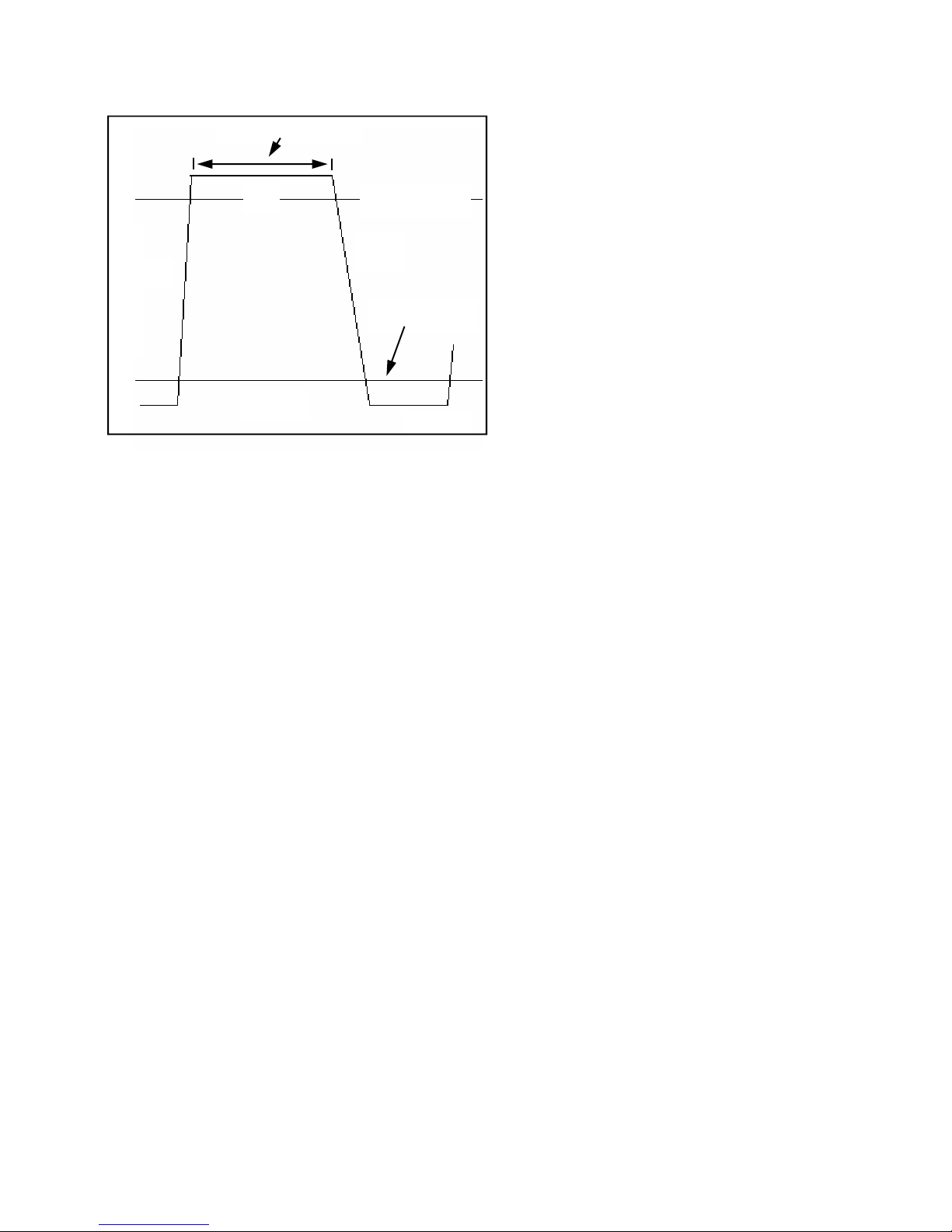
Pulsator Ratio
The Pulsation measurements are
calculated based on four time intervals
called A, B, C and D. These intervals
indicate the various phases of pulsation
which are marked by a crossing of the
vacuum levels 1.2" Hg above the minimum
and 1.2" Hg below the maximum vacuum
of the single pulsation cycle. A typical
pulsation cycle and the A-B-C-D points are
depicted above.
For pulsation measurements, the
beginning of a pulsation is considered to
be the point that begins the A phase of the
curve, at time a. Calculations are as
follows:
Total Time = a' - a
Pulses Per Minute = 60 seconds / Total
Time
Min / P = Minimum vacuum per pulse
Max / P = Maximum vacuum per pulse
B Fluc = Fluctuation in the B phase
A(time) = b - a
B(time) = c - b
C(time) = d - c
D(time) = a' - d
A+B(time) = A(time) + B(time)
C+D(time) = C(time) + D(time)
A% = A(time) / Total Time * 100%
B% = B(time) / Total Time * 100%
C% = C(time) / Total Time * 100%
D% = D(time) / Total Time * 100%
A+B% = A+B(time) / Total Time *100%
C+D% = C+D(time) / Total Time *100%
Setting Pulsator Ratio Limits
Limits for the individual pulsation
parameters can be set for the Pulsator
Ratio Function.
See page 40 for default settings.
The Digimet 3000 Version 4.0 allows users
to set limits for pulsator ratio
parameters, like a high and low value for
the B phase of pulsation. When a user is
collecting data with the Digimet 3000, the
26
Page 27

Digimet 3000 display will blink when a
parameter value falls outside the
desired limits. This will give guidance to a
user as to a potential problem with a
pulsator and/or an indication of values that
are not appropriate.
Limits for the following Pulsator Ratio
parameters can be set:
• Minimum and Maximum limits can be
set for Maximum Vacuum per Pulse; A,
B, C & D Phases; and Pulses per
Minute.
• A Maximum limit can be set for B
Fluctuation and a Minimum limit can be
set for Minimum Vacuum per Pulse.
When viewing data in real time or
viewing stored data, the values that are
outside the set limits will blink on the
Digimet display.
To set limits, first go to the Utility Menu
which is the Function Menu number 5.
Press the Enter key, then the down arrow
key to Set Pulsator Limits which is number
11 in the Utility Menu. 11 Set Pulsator
Limits is the last item in the Utility Menu.
Then press the Enter key.
To set limits, move the arrow at the left, by
pressing either the Up or Down arrow key.
When the arrow is beside the parameter
that you desire to set limits, press the
Enter Key. An E will appear in the upper
right corner of the Digimet display
indicating that you are in the Editing Mode.
Use the Up or Down arrow keys to set the
desired values.
Limits for the following Pulsator Ratio
parameters can be set:
B Fluc Max can be set from 0.00 to 3.00 in
increments of .50 inches Hg.
Max Hi Vac/Pulse can be set from 5.50" Hg to
16.00" Hg in increments of 0.50 inches of Hg.
Min Hi Vac/Pulse can be set from 5.00" Hg to
15.50" Hg in increments of 0.50 inches of Hg.
Min Vac / Pulse can be set from 0.00" Hg to 4.00"
Hg in increments of 0.50 inches of Hg.
Max A Phase can be set from 30 to 300 in
increments of 1 msec and must be at least 10
msec greater than Min A Phase.
Min A Phase can be set from 20 to 290 in
increments of 1 msec and must be at least 10
msec less than Max A Phase.
Max B Phase can be set from 110 to 750 in
increments of 1 msec and must be at least 10
msec greater than Min B Phase.
Min B Phase can be set from 100 to 740 in
increments of 1 msec and must be at least 10
msec less than Max B Phase.
Max C Phase can be set from 30 to 500 in
increments of 1 msec and must be at least 10
msec greater than Min C Phase.
Min C Phase can be set from 20 to 490 in
increments of 1 msec and must be at least 10
msec less than Max C Phase.
Max D Phase can be set from 110 to 500 in
increments of 1 msec and must be at least 10
msec greater than Min D Phase.
Min D Phase can be set from 100 to 490 in
increments of 1 msec and must be at least 10
msec less than Max D Phase.
Min PPM (pulses per minute) can be set from 20 to
198 in increments of 1 PPM and must be at least 2
PPM less than Max PPM.
Max PPM can be set from 22 to 200 in increments
of 1 PPM and must be at least 2 PPM greater than
Min PPM.
Press the Enter key to Save that
parameter. To set another parameter, use
the same procedure. To exit Set Pulsator
Limits, press the Menu key.
If measurement Units is set to kPa then
the pulsator parameters must still be set in
Inches of Mercury but readings will
respond to their kPa equivalent.
B-Phase Fluctuation
B Fluc stands for B-Phase Fluctuation and
is a parameter that appears on the
27
Page 28

third line below C+D % ms in the Pulsator
Ratio function. B Fluc is displayed in either
“Hg or kPa and is the amount of fluctuation
during the B Phase of the pulsation wave
as calculated by the Pulsator Ratio.
The B phase of the Pulsator Ratio is the
phase which corresponds to the open and/
or milk phase. The B Fluc parameter is
intended to give an indication of movement
within the top portion of the B phase,
which would ideally be straight. Since, the
B phase begins at 1.2” Hg below
Maximum vacuum on the upwards slope of
the curve and continues to 1.2” Hg below
Maximum vacuum on the downwards
slope, the end points of the B phase are
excluded from evaluation in the B Fluc
parameter. Technically, 1/16 of the B
phase at both the beginning and the end of
the phase are not included in the B Fluc
calculation. Therefore, 87.5% of the B
phase is evaluated, with the difference
between the maximum level and minimum
level during that period outputted as B
Fluc.
Milk/Rest Ratio
The Milk/Rest ratio is the ratio of the time
when the teat cup liner is not collapsed
(Milk) to when it is collapsed (Rest).
Collapse of the liner is based on the
differential of a pulsating vacuum (vacuum
and atmospheric air) on the outside of the
liner, between teat cup and liner, and a
(relatively) steady vacuum on the inside of
the liner.
The point on the pulsation curve at which
the liner collapses should be determined
by the user. This is a simple and
straightforward calculation:
A. Determine the average vacuum at teat
end using the DIGIMET 3000 with its
Vacuum Level Function.
B. Determining the differential pressure
required to collapse the liner needs to be
determined. The differential pressure
required to collapse the liner is generally:
1) specified by the liner manufacturer; 2)
specified by other sources; 3) determined
by a simple test; or 4) determined using
several rules of thumb:
RULES OF THUMB: Thin-walled liners, on
the average, require a differential pressure
of 2" Hg in order to collapse. Mediumwalled liners require, on the average, 5"
Hg of differential pressure to collapse.
Thick-walled liners need, on the average,
7" Hg of differential pressure to collapse.
Based on the two values found in A and B,
a point referred to as the Liner Collapse
Point (LCP) is determined:
LCP = Average Vacuum - Differential
Pressure to collapse liner
The DIGIMET 3000 allows LCP selection
by the user; any average vacuum and liner
differential pressure combination can be
accommodated (see Liner Collapse Point
in the Utility Menu section).
To calculate the M/R ratio, the current
input sample is compared against the
currently set LCP. If the input vacuum is
greater than or equal to the LCP, the
pulsator is in the Milk phase; otherwise, it
is in the Rest phase.
The following calculations are made:
Total Time = Milk Time + Rest Time
Ratio Milk = Milk Time / Total Time *
28
Page 29

100%
Ratio Rest = Rest Time / Total Time *
100%
Max / P = Maximum vacuum per pulse
Min / P = Minimum vacuum per pulse
Pulses per Minute = 60 sec/Total Time
Note: Regarding Pulsator Ratio or Milk/
Rest Ratio function data which appears
on Digimet Printer graphs or computer
graphs: The numeric data represents
the last complete waveform
which
appears on the graph.
Pulsation Electronic
The method of calculating the PulsationElectronic measurements is similar to the
Milk/Rest ratio. Here, the trip point is fixed
at 6 volts. This allows a good indication
for the beginning and end of a pulse in
either 0-12 or 0-24 volt systems. The two
time intervals, ON interval and OFF
interval, are calculated along with the
absolute minimum and maximum voltage
values. At the end of each pulse, the min/
max values are reset.
The following is then calculated:
ON = On Interval / Total Time * 100%
OFF = Off Interval / Total Time * 100%
Max V/P = Maximum voltage DC per
pulse
Min V/P = Minimum voltage DC per
pulse
Pulses per min. = 60 sec / Total Time
CALIBRATION
The DIGIMET 3000 requires factory
calibration in order to characterize the
various components in each particular unit.
Because of the high accuracy and stability
over time of the components, subsequent
calibrations are generally not anticipated.
However, since the DIGIMET 3000 may be
exposed to conditions that could be harsh
for an electronic instrument (roughly
handled, left on a hot car seat for a day,
etc.) it is a good idea to periodically check
the DIGIMET 3000 against a known
accurate standard. To insure accuracy it is
recommended to return the Digimet 3000
to the factory for re-calibration once per
year.
Unit Initialization
The DIGIMET 3000 leaves the factory with
the following initial settings:
Storage Memory Cleared
Time Frame = 1 sec
LCP = 6.5" Hg
Display Units = " Hg
Type Pulsation - Single
Auto Shut-off set at 10 minutes
Auto-Zero
When the DIGIMET 3000 is set to the
Vacuum Level Function with no input, it
will auto-zero. See section on Auto-Zero
for further details.
HARDWARE SPECIFICATIONS
This section describes the DIGIMET 3000
hardware design.
Microprocessor
The DIGIMET 3000 uses a Motorola
microprocessor to provide the system
functions. The microprocessor runs at 4.0
Mhz.
Power Subsystem
The power system is supplied by four AA
alkaline batteries.
29
Page 30

Vacuum Sensing
The external vacuum source is attached to
the DIGIMET 3000 via a male luer quickdisconnect fitting attached to the port
labeled VACUUM.
Electronic Pulsation Input
The electronic pulsation input is designed
to accept an oscillating voltage between 0
and 24 DC volts at a maximum of 40.0
Amps. The polarity of the input signal is
rectified to guarantee that all voltages are
positive. An RC filter is used on the input
to eliminate sharp voltage spikes that
occur during solenoid switching.
DIGIMET PRINTER
The Digimet Printer is an OmniPrint
OM190 Serial Printer which uses a AC
wall transformer to supply it with power. Its
operation as it relates to use with the
Digimet 3000 will be outlined here.
Digimet Printer Settings
The Digimet Printer is set at the WDR
factory for use with the Digimet. Those
settings are:
Baud rate = 9600
Data Bits = 8
Parity = NONE
Stop Bits = 1
Digimet Printer Operations
The Printer uses adding machine 2 1/4”
inch rolls of paper. The printer ribbon is an
Epson HX-20 cartridge ribbon. These
items can be obtained at WDR or at your
local stationary/computer store.
The Digimet Printer will need to be
connected to the provided AC transformer
which is plugged into 120 AC power.
See the section on CABLES to determine
the properly cables to use with the Printer
and Digimet.
Digimet Printer to be used with the
Digimet 3000
The Digimet Printer unit consists of the printer
and power supply. The paper roll and printer
ribbon are stored within the printer enclosure.
To turn the printer on – press the ON button
(ON button blinks green).
To turn the printer off – press and hold the
OFF button until the FEED button blinks red.
(the button blinks once, quickly)
When printing, the ON button appears solid
green.
After printing, the FEED button will need to be
pressed to see all that has printed.
Note: If, when initiating printing, nothing
happens, do one or all of the following: 1)
Make sure there is saved data in the Digimet
2) Make sure the Digimet Printer is ON 3)
Make sure the connector at the Digimet and at
the Digimet Printer are snug 4) Turn off the
Digimet Printer and the Digimet and start over.
To open the printer to change paper or to
change the print ribbon, lift the top cover up.
To close, lower the top cover and press
slightly forward to close completely.
Paper rolls are 2 ¼ inch (57 mm) wide and are
adding machine paper rolls. If the roll is too
tight in the printer compartment it might be
necessary to remove some of the paper from
the roll.
To run a printer test, turn off the printer then
press the FEED button and the ON button at
the same time. When the printer stops printing
the first time while running the printer test,
press the FEED button, again. The instructions
to do so appear below the tear edge of the
printer.
Note: Sometimes lights may appear dim on
the printer but you can determine whether or
not the unit is on by pressing the FEED button.
If the printer feeds paper, unit is ON, if not, the
unit is OFF.
30
Page 31

SOFTWARE
Two programs are provided with the
Digimet 3000, one a Windows program
and the other a DOS program. The
Windows program called BigTree
Digidata.exe is for uploading, displaying
and printing data from the Digimet 3000.
The DOS program, BigTree Upload.exe is
for uploading data from the Digimet 3000
to a computer, ONLY. It is provided as a
secondary method for uploading data from
the Digimet.
Computer Requirements
1- in order to upload data from the Digimet
to the computer an unused COM port is
needed on the computer. All cables
provided with the Digimet and Digimet
Printer would require a 9-pin male com
port at the computer. As long as there is
an unused com port, adapters can be
found to ultimately connect to the needed
9-pin connectors of the Digimet cables.
(USB to serial 9-pin connectors can also
be used)
To Upload data from the Digimet to a
computer:
1. Collect and Store data in the Digimet.
2. Connect the Digimet and the computer
with the 6’ computer cable. One end
connects to the Digimet serial port. The
other end connects to the computer’s 9-pin
serial port (com port).
3. Use either the DOS program
Upload.exe or the WINDOWS program
Digidata.exe.
DOS program Upload.exe
The Upload.exe program is a DOS
program used to upload data from the
Digimet to the computer. The Upload.exe
program is supplied on the computer disk
which accompanies the Digimet. It can be
loaded to your hard drive by entering at
the prompt
>COPY A:\UPLOAD.EXE C:\
To run the program, either in DOS or a
Dos window in WINDOWS, simply get into
the proper directory and type in UPLOAD.
Follow the commands on the screen. The
default file name for your file to be
uploaded is upload.dat, but you can name
your files what ever you want. Other
sections in this manual will explain what
commands are used in the Digimet to
upload data to the computer; Print/Upload,
Upload/Print all data, Upload Graphic
Data, Print Graph and Print Limping data.
When you are ready to upload data to the
computer, run upload.exe. The screen will
indicate that it is waiting for data. Note: If,
before you initiate the Digimet to send
data, you see a few characters on the
computer screen, start the procedure
over. Then press the appropriate keys on
the Digimet. When the Digimet has
completed the upload, press the Enter key
on the Computer to close the file. Your
upload.dat file or what ever you have
named it will be ready to be viewed,
printed etc. To determine when uploading
is complete see section When is
Uploading complete.
When using upload.exe, the default name
is upload.dat but you can change this to
anything you would like. Now, if you are
saving a number of files then you would
change the upload part to something else
or you would continually save over your
existing file. You could name them
graph1.dat or dairy.dat. You do not need
to keep the .dat ending, either.
WINDOWS program DigiData.exe
The WINDOWS program is on the disk
provided with your Digimet and can be
31
Page 32

loaded into your computer by running the
Setup program. This section will outline all
the functions of the program.
Click on the Digimet icon to run the
program.
To view data, open a file that has been
previously uploaded and saved or upload
data by using the commands at the right
hand side of the display.
Upload Item
From the Digimet screen in any of the four
functions, choose Print/Upload. Select the
item by choosing your labeled or timerstamped item. The next screen will
indicate that after pushing the Enter key
you will send data to the Digimet. BUT,
before taking that last step, put the
computer program into the Upload mode,
to accept the data from the Digimet, by
clicking the Upload Item command in the
upper right corner of the screen. At this
point, the command button on the
computer will have changed to Done
Upload Item and will be highlighted in red.
Now, press the Enter key on the Digimet.
As soon as the option screen appears on
the Digimet this is the signal that the
Digimet has completed the send. Now, on
the computer screen, click the Done
Upload Item. This will place the data in the
computer and in the appropriate function
screen. See section on CABLES in order
to properly hook the Digimet to the
computer.
Viewing Data
The Digimet data can be viewed in either a
standard format or grid format. This choice
is made in the Menu item, VIEW. In the
Standard Mode, the number of the Tab will
be red if there is data in the storage item.
You can use the mouse or arrow keys to
move to different tabs.
Notes
The window below the main window in the
Standard Mode is used for notes referring
to the item chosen. Notes only appear in
the Standard viewing mode. Notes will
appear on the print-outs. In the dual
pulsation storage mode, only one set of
notes is available for a dual chamber
pulsator.
MENU
File - New
Start a new file.
File - Open
Open files that contain data that has been
previously uploaded from the Digimet. The
files end with .dm3. Only that type of file
(.dm3) will be retrieved into the digidata
program for display of numeric data.
File - Save As
Files that can be saved have a .dm3
ending. When saving numeric data, the file
must end with .dm3. The Save BMP
command saves a bitmap graphic picture
of the graphs that are displayed in this
program. One note, they are big files
approximately 250k bytes.
It is not necessary to save graph files as
BMP files. This would only be necessary if
you wished to save graphs to view in other
programs. The .dgr graph files, which can
be viewed by the DigiData.exe program
are redisplayed each time from the original
data .dgr files. Also, to save a file as
a .BMP, you must be viewing a graph file
on the computer screen with the Display
Graph command.
File – Set Printer Font
32
Page 33

Use this feature to obtain the most
desirable printout.
File - Print
The following are print options to the
printer attached to your computer:
Print Vacuum Level Data in either a
standard or grid format. Print Pulsation
Electronic data. Print Pulsator Ratio data
in dual or single display mode. The dual
print will include comparisons of the two
chambers of the dual pulsator. Print the
Milk/Rest ratio data in grid format. The
next to last print option is Print Graph. This
will print the graph that is displayed with
Display Graph. The Start time of the
printed graphs is indicated at the left
corner of the graph. The graph increments
is also indicated at the bottom of the
graph. Graph increments are 250
milliseconds. A graph printout is shown on
page 47. The last Print option is Print
Limping Data and consists of the Limping
data calculations.
File - Exit
Exit the DigiData program. A warning
window will appear recommending that the
numeric data be saved to a file.
Options - Label Data Set
Label data file with up to 16 characters.
Options - Set Com Port
Com port 1, 2 , 3 or 4 can be used to
upload data from the Digimet. If the wrong
Com port is set or the one chosen is
presently in use by some other device, like
the mouse, the program will exit if you
press the Upload Item, Upload All, Upload
Graph, Rec. archive data command
buttons. This is the Com port that you will
use to connect the Digimet to the
computer.
Options - Type Pulsation
This option only effects the Pulsator Ratio
and the M/R ration functions. In the Dual
mode the items are labeled 1A-1B etc., in
the single mode the items are labeled 1, 2,
3 etc. when viewing the standard viewing
mode. In grid viewing mode, in single
mode the items are listed one after the
other. In the Dual mode, each two items
are compared.
Options - Graphing
This allows you to set the following options
for graphs 1) Minimum and Maximum lines
will appear on the graphs, 2) the number
of Y axis ticks can be chosen and 3)
vertical grid lines can be used.
Options – Set Pulsator Limits
Refer to page 27 of this manual for
information about setting pulsator limits.
Same limits can be set in the Digidata
program as in the Digimet 3000 Version
4.0 unit. In the Digidata program the terms
Max. Vac / P - Maximum and Max. Vac / P
– Minimum are referring to the terms
MaxHiV/Pls and MinHiV/Pls in the Digimet
3000. All other terms are the same as
appear in the Digimet 3000 Utility Menu –
Set Pulsator Limits.
Options – View Pulsator Limits
This will show the limits that have been set
for the corresponding pulsator parameter.
View Grid or Standard
Grid view or standard view are the
choices.
View Inches Hg or kPa # IMPORTANT #
When measurement units are set to
inches of Hg or set to kPa in the
33
Page 34

Digimet 3000, the corresponding
measurement should be clicked here so
that the proper calculations take place
regarding the indication of whether or
not a value is acceptable or outside the
limits set in Options – Set Pulsator
Limits menu item. The Default is set to
Inches of Hg.
Graph Settings
When the graph screen is visible ie. the
Display Graph command is pressed and a
graph is being viewed then by pressing the
menu item Graph Settings, the min/max
“Hg and the start and finish times for the
graph can be chosen.
Help
Displays phone number for assistance
which is 1-800-635-6413 or 949-598-9700
or Fax 949-598-9075 or email
[email protected].
At the right side of the screen are 7
command buttons. Note: Two of the
command buttons Send to D. Printer and
Rec. archive data are not used.
Upload Item
This command is used to accept the
uploaded data from the Digimet when the
Print/Upload command is entered on the
Digimet. The Print/Upload command
appears in the Options Menu of each of
the four functions, Vacuum Level, Pulsator
Ratio, M/R Ratio and Pulsation Electronic.
Here are the steps for Upload Item (Print/
Upload data from the Digimet): 1) Hook up
Digimet to computer using 6 foot computer
cable with 9-pin connectors on each end.
2) With both the computer and the Digimet
ON, go to the Print/Upload command in
the Function you wish to Upload, pressing
Enter will take you to the Menu to choose
the specific item you wish to upload. The
next screen will say Send Slot 01 (with the
label indicated) Enter to send. Menu to
exit. Before you go any further, go back to
the computer and press the Upload Item
command button. This will ready the
computer for the transfer of data. Pressing
the Enter key, now, on the Digimet will
send data to the computer. As soon as the
screen is back to the Options Menu (the
Digimet), this is the signal that the transfer
is complete. On the Digimet, the words No
Clear to Send may appear at the bottom
of the screen (the Digimet). This is
perfectly normal. As the buffer fills up in
the receiving machine (Digimet Printer or
computer) this signal will appear. Now if
these words stay indefinitely then there
probably is something wrong with the
connection. See the section on
TroubleShooting. Then press the same
command on the computer which now
reads (in red) Done Upload Item. At this
point the upload has taken place and the
Digimet data will be in the appropriate
storage area in the computer program. For
example, if you are viewing the Standard
View then the tab number of the storage
item uploaded will be highlighted in red. If
you click on the tab the data will appear in
the window in the center of the screen. If
you are viewing the grid view then the data
will appear under the appropriate column
number. This would be the procedure for
each item that you wished to upload. This
data along with other uploaded items can
be saved to a file using the File - Save As Save As (data, archive files). These files
can be saved with a .dm3 ending. Dm3
files can be viewed again on the computer
by File-Open. Only dm3 files can be
viewed on the computer screen. See
section on Saving Files.
34
Page 35

Upload All
In the Utility Menu of the Digimet there is
the Upload-Print all Data command. This
will upload all the numeric data at the
same time from the Digimet to the
computer.
First, connect the Digimet and the
computer,
Second, press Upload All command on the
computer screen, Third press Upload-Print
all Data item number 1 in the Digimet
Utility Menu. As soon as you do this, the
word Menu to abort will appear at the
bottom of the Digimet screen. When that
goes away the Digimet has completed the
send. Now, press the Upload All
command, (which is now Done Upload All.
in red) on the computer screen.
Note: If you have a Digimet version 3.0
and above, do the First step as listed
above, but continue with the Second
step here:
Second, Press the Upload All command
button on the DigiData screen. The caption
on the button will change to Press Enter-
Digimet. Press the Enter key on the
Digimet. The caption on the button on the
DigiData screen will change to
Uploading. When the computer and
Digimet are done uploading, the program
will beep and the caption on the button will
change to Press here-Done. Press the
button and the Digimet 3000 data will
appear in its respective slots in the
DigiData program.
Note: If you are uploading just a few items,
for example, 2 Vacuum Level items, you
may need to press the Enter key a few
times to get the button to change from
Press Enter-Digimet to Uploading.
All your data will now be in their
appropriate slots in the program. Note:
This data is now in the computers memory
to save it you must go to File - Save As Save As (data, archive files) and save data
to a file. These files can be saved with
a .dm3 ending. Dm3 files can be viewed
again on the computer by File-Open. Only
dm3 files can be viewed on the computer
screen. See section on Saving Files.
Upload Graph
This command is for uploading graphs
from the Digimet to the computer meant
for display on the computer. Let me
explain, the Digimet stores two types of
graphs, 1) graphs for display on the
Digimet Printer and 2) graphs for display
on the computer monitor. Graphs viewed
on the computer monitor could also be
printed to the computers printer.
Graphs are transferred from the Digimet
using the Upload Graphic Data command
in the Digimet Utility Menu. The Upload
Graphic Data command would be chosen
in the computer and the graph would be
saved as a .dgr file in the computer. This
graph can be displayed on the computer
screen with the Display Graph command.
The Upload Graphic Data command on
the computer screen is specifically for
graphs that will be viewed on the computer
screen and not graphs that will be printed
to the Digimet Printer.
Upload graphic data from the Digimet to
the Computer using the following steps:
1. Connect the 6 foot serial cable to the
Digimet and the computers serial port.
2. Open the Digidata program.
35
Page 36

3. Go to the UTILITY MENU item 2
Upload Graphic Data on the Digimet.
4. Press Enter on the Digimet.
5. Choose your Graph to upload on the
Digimet.
6. Press Enter on the Digimet, one time.
7. Press the Upload Graph button on the
Digidata computer screen, the button
will change to “Press Digi then Here”.
8. Press Enter on the Digimet one more
time.
9. Press the “Press Digi then Here”
button. Button changes to
“******Uploading.” As uploading is
taking place this button will change to
“*****Still Uploading”. When uploading
is completed the button will say “*Done
Uploading”. The Save Graphic file
window will then appear. Choose a
name for your graph file and be sure it
ends with .dgr.
10. Press the OK button in the Save
Graphic files window.
11. Your graphic file has been uploaded
from the Digimet and saved as a
computer file.
Display Graph
Use the Display Graph command on the
computer screen to display a saved graph.
You will be asked for the file name. All
graph files for display are saved as .dgr
files. After choosing the file name the
graph will appear on the screen. While a
graph is being displayed the Display
Command button changes caption to
Close Graph and is in red. Choose Close
Graph to close. If Graph Settings (see
below) have been changed re-display
the graph using the Regraph button
which is located next to the Close
Graph button.
While a graph is being displayed, the
Menu item Graph Settings at the top of
the screen is enabled. By clicking on this
item, four graph variables can be set. 1)
Maximum vacuum level 2) Minimum
vacuum level 3) Start time for the graph
and 4) Finish time for the graph. The
reason for Start and Finish times is
because the Digimet can store up to a 10
second graph but you don’t have to view
the whole graph on the computer screen.
You can look at just a portion of the graph
by setting Start and Finish times. To
remove the graph variables from the
display click on Graph Settings again.
Send to D. Printer
Not Used
Rec. archive data
Not Used
Graph data
When a graph is being displayed on the
computer screen, pertinent data regarding
the graph appears in a window in the lower
right area of the computer screen. This
data also prints out with the graph when
printed.
Saving Files
This section will explain what different
computer files are saved when using the
software for the Digimet 3000.
.dm3 files - These files can be viewed in
the Windows program DigiData.exe. They
are the numeric data files.
.dgr files - These files would be graphic
data files that are uploaded to the
36
Page 37

computer using the Upload Graphic Data
Utility Menu command and meant for
viewing on the computer display either
with the Windows program DigiData.exe or
another computer program. (See the
section on Use of other programs.
When is Uploading complete?
This section will explain when uploading
has been completed.
1) When using the Print/Upload item from
the Digimets Option Menu after you have
chosen the item to upload, you will be in
the Send Slot screen of the Digimet. After
you press the Enter key, the Digimet will
send the data. When the Option Menu
screen re-appears, uploading has ended.
2) Using Upload-Print all Data from the
Utility Menu, when you initiate sending
data on the Digimet by pressing the Enter
key, the bottom line on the Digimet screen
will say “Menu to abort”. When this line
goes away, uploading is complete. Note: If
the message “No Clear to Send.” appears
and remains on the screen, then there is a
problem with the connection, possibly the
computer is not on or the com port is not
the correct one.
3) Upload Graphic Data - See the previous
section titled Upload Graph.
Use of other programs
Other communication programs can be
used to receive data from the Digimet into
the computer. The Digimet utilizes the
serial communication standard EIA-232,
formerly RS-232. Settings would need to
be Baud rate=9600, Data BITS=8,
Parity=None and Stop Bits=1. The data is
sent in ASCII format.
Once data is transferred to the computer
either with another communication
program or with the DOS program
provided, other spreadsheet,
wordprocessing etc. programs could be
used to view the data. Also, the graph files
that are sent to the computer by using the
Upload Graphic Data command in the
Digimet can be viewed by other graphing
programs.
CABLES
There are two types of cables that are
provided:
A six-foot computer serial cable with a
male 9-pin D-sub connector at one end
and a female 9-pin D-sub connector at the
other is provided with the basic Digimet
package and would be needed for any
uploading to a computer.
The other cable is used with the
Digimet Printer. The Digimet Printer cable
is a short cable with a 25-pin male at one
end and a 9-pin male connector at the
other. This cable connects to the Digimet’s
serial port with the 9-pin end. The other
end connects to the Digimet Printer (the
25-pin male end).
Note: A 9-pin female com port is
necessary on the computer. If a 9-pin
connector is not available, adapters can
be obtained from your local electronics
store. When hooking up cables to the
Digimet 3000, the Digimet Printer or your
computer serial port, it is not necessary to
turn them OFF.
PARTS LIST
Standard Carrying Case DM3-FCASE
Large Carrying Case DM3-LCASE
5/32” Plastic tubing DM3-TUBING5/32
Needle connector DM3-16-01
Stainless needle DM3-17
Acrodisc filters DM3-15
Plug (vacuum port) DM3-16-06
Male Quick Disconnect luer fitting DM3-16-03
37
Page 38

Banana Plugs (both red & black) DM3-08
Grommet (at vacuum input) DM3-14
Batteries (4 AA) DM3-19-01
Pipe fitting (1/8-27 NPT to 5/32) DM3-PIPE
Pipe fitting plug DM3-17-02
Pulsator fitting DM3-18
Computer cable 6’ DM3-COMPC6
Printer cable DM3-PCABLE
Dust cover 9-pin DM3-DUSTC
AC transformer DM3-ACTRANS
Digimet Printer DM3-PRINTER
Digimet Software Disk DM3-DISK
MISCELLANEOUS
Tapping Holes for vacuum test points
Tapping holes for pipe fitting DM2000-1701 (1/8-27 NPT fitting) can be
accomplished as follows:
A 1/8-27 NPT fitting requires a 11/32" tap
drill, then tap threads with a 1/8-27 NPT
tap. Pipe threads are tapered. This
usually requires a tapered reamer, which
is not necessary for thin, soft materials
such as plastic pipe. When tapping, do
not go too deep. It's easy to do so in thin
pipe walls.
Comparing Electronic and Pneumatic
Pulsation
Electronic and pneumatic pulsation
readings will differ because of the
following:
1) Since the electronic wave is a square
wave and the pneumatic wave is sloped,
the calculated ON/OFF ratios will differ to
a small degree.
Depending on where ON time (milk time)
is calculated on the pneumatic wave, for
example, the ratio will be affected. In the
Milk/Rest function, the user selects the
Liner Collapse Point, affecting the point on
the wave at which the ratio is calculated.
2) Pulsation-chamber vacuum does not
move as quickly as an electronic voltage
signal.
3) Condition of the liner and other rubber
goods may influence readings.
4) Finally, the pulsators may not be
operating properly due to air leaks, etc.
Cleaning
The DIGIMET 3000 can be externally
wiped clean with a damp cloth and mild
dishwashing soap. Tubes should be
periodically flushed with water to remove
milk residues.
Acrodisc filters are provided to protect
against the intrusion of milk onto the
transducer membrane. If milk is allowed
to enter the unit and to dry, performance
of the DIGIMET 3000 most likely will be
affected. If milk gets into the transducer
inlet, immediately rinse it out in the
following manner: Using a syringe, shoot
a small amount of rubbing alcohol,
GENTLY into the vacuum port.
IMPORTANT: DO NOT INSERT THE
NEEDLE FURTHER INTO THE PORT
THAN THE FACE OF THE UNIT (I.E.,
ONE SHOULD STILL BE ABLE TO SEE
THE NEEDLE POINT). DOING SO MAY
CAUSE DAMAGE TO THE
TRANSDUCER MEMBRANE. Let the
alcohol drain out. Rubbing alcohol is
preferable to water because water will
leave a residue plus, alcohol will
evaporate fairly quickly while water will
not.
38
Page 39
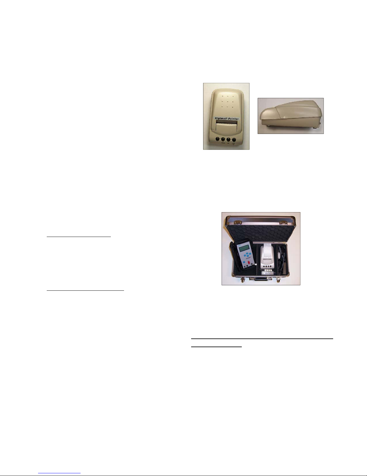
Use of Stainless Needle
When using the needle to puncture
rubber components, be sure the inside of
the needle is absolutely clear of
obstructions. A thin piece of wire can be
used to clear the inside of the needle of
any obstruction once the needle has
been inserted into the rubber component.
Obstructions, i.e. small pieces of
rubber inside the needle, will affect
readings.
Serial Number
The DIGIMET 3000 serial number is
located on the back of the unit at the
bottom of the label. It also appears on the
initial screen when the unit is turned on.
Configurations
The Digimet 3000 is sold in a few
different configurations depending on the
users’ requirements.
Basic Digimet 3000:
This package includes the Digimet 3000,
Standard Carrying Case, tubing &
accessories, computer cable, computer
software disk and manual.
Digimet 3000 Complete:
This package includes the Digimet 3000,
Large Carrying Case, Digimet Printer, AC
wall transformer, tubing & accessories,
printer cable, computer cable, computer
software disk and manual.
The following items can be purchased
separately:
Digimet Printer:
Side view
Large Hard Carrying Case: This case can
hold the Digimet 3000, accessories, the
Digimet Printer & cables and the AC wall
transformer.
Packing List
Depending on the configuration purchased,
your shipment could include different items.
Items included with your Basic DIGIMET
3000 packaging.
1. DIGIMET 3000
2. Standard Fabric Carrying Case with strap
(continued on next page)
39
Page 40

Inside compartment or laying on face of
DIGIMET 3000:
(1) 4' length of plastic 5/32" tubing with small
hose clamp and Acrodisc attached.
Small container includes:
(3) plastic tie wraps – for attaching
Acrodisc filters to the tubing. Tighten tie
wrap, then cut off excess.
(3) needle connector
(1) Acrodisc filters
(1) Stainless needle
(1) 1/8-27 NPT fitting
(1) 1/8-27 NPT plug
Also enclosed in case:
(2) “T” Pulsator fitting
(1) Set of banana plugs (red and
black)
(4) AA Alkaline Batteries
(1) Computer cable 6’
3. Outside of carrying case, inside shipping
box:
CD with computer software
Operator's Manual
Additional accessories could include the
following:
Digimet Printer - Printer, AC wall
transformer and printer cable.
Large Hard Carrying Case with carrying
strap
Trademarks
Windows & DOS refer to products
copyrighted by the Microsoft Corporation.
Digimet is a registered trademark of L. J.
Engineering, Inc. This manual is
©Copyright L. J. Engineering, Inc. 2001-
2009. All rights reserved.
Troubleshooting
Error #380 - If you get this error when
trying to display a graph, the digidata.ini
file is missing, possibly. It should be in the
same directory that the digidata.exe
program resides. If, for some reason, the
DigiData.ini file gets corrupted, there is an
original copy which can be used which is
located on the distribution disk. Also, this
error may mean that the file path length is
too long for the graph title. The graph title
is limited to 80 characters.
Not a .dgr file - If you get this message
when trying to load a graphic file into the
DigiData program - Upload Graph, it may
be that you saved a file and gave it a dgr
ending, but it is not a real .dgr file. Or you
are trying to load a file that does not end
in .dgr.
Default Pulsator Ratio parameter limits:
Bfluct Max – 1.00, MaxHiV/Pls – 13.00
MinHiV/Pls – 12.00, MinVac/Pls – 0.00
MaxAPhase – 150 ms, MinAPhase – 80 ms
MaxBPhase – 560 ms, MinBPhase – 480 ms
MaxCPhase – 150 ms, MinCPhase – 80 ms
MaxDPhase – 250 ms, MinDPhase – 200 ms
Max PPM – 62.0, Min PPM – 58.0
L. J. Engineering, Inc. has set these default values
because in their opinion these parameter limits fall
within the acceptable ranges which they are most
familiar with. These default values are in no way
cast in stone. We would recommend that the user
of the Digimet 3000 consult their equipment dealer,
the company that provides their equipment, the
manufacturer of the equipment and/or dairy
equipment consultants, etc., to determine the best
values for their equipment and systems.
40
Page 41
Graphs & Printouts
The following pages will examine the
different printouts that can be printed
with the Digimet 3000 and the Digimet
Printer. Refer to other parts of this
manual for information on printer
operations and correct hook-up to the
Digimet 3000.
Printed material can be obtained by
using the commands listed below:
From each of the function’s Option
Menu, the Print/Upload command will
print numeric data for each item stored
similar to Recalling an item and viewing
it on the Digimet 3000 display. The data
listed below is a representation of the
information that would print from a stored
Vacuum Level item:
VACUUM LEVEL
Barn #1 at trap
Location Timer
01 01:52:47
Ave 12.01 “Hg
Max 12.03 “Hg
Min 11.99 “Hg
Fluc 0.04/ 1 sec period
All numeric printouts will have a similar
format.
Function
Label (up to 16 characters)
Location refers to slot storage number
Timer stamp
Ave, Max Min and Fluc data
Fluctuation time frame
41
Page 42
The Pulsator Ratio Function data printout is
shown below:
PULSATOR RATIO
Location Timer
01 01:56:55
A+B 49.9% 582 msec
C+D 50.1% 584 msec
B Fluc 0.11”Hg
Max/P 12.00”Hg
Min/P 0.00”Hg
A 4.8% 56 msec
B 45.1% 526 msec
C 8.9% 104 msec
D 41.2% 480 msec
Total 1166 msec
PPM 51.4
The Milk/Rest Function printout data appears
below:
MILK/REST RATIO
Pulsator A
Location Timer
02 02:01:04
Ratio 50/50
Pulses/Min 51.8
Max/P 12.00
Min/P 0.00
Milk 50.3%
Milk 582 msec
Rest 49.7%
Rest 575 msec
LCP 6.50”Hg
Total: 1157 msec
Function heading
If no label is chosen then this
space will appear blank.
Location
Timer stamp
Function data
Function heading
Label
Location and Timer stamp
Function data
42
Page 43

The following is print-out data for the
Pulsation Electronics function:
PULSATION ELECTRONICS
Box #2
Location Timer
01 02:03:05
On 50.3%
Off 49.7%
Max/p 24.3Volts
Min/p 0.0Volts
Pulses/Min 51.7
To obtain a print-out of all the numeric
data stored in the Digimet 3000, at one
time, use the Utility Menu item 1
Upload-Print all Data. This is item 1 in
the Utility Menu. All the data will print
out, one item after the other.
Function heading
Label
Location slot and timer stamp
Function data
43
Page 44
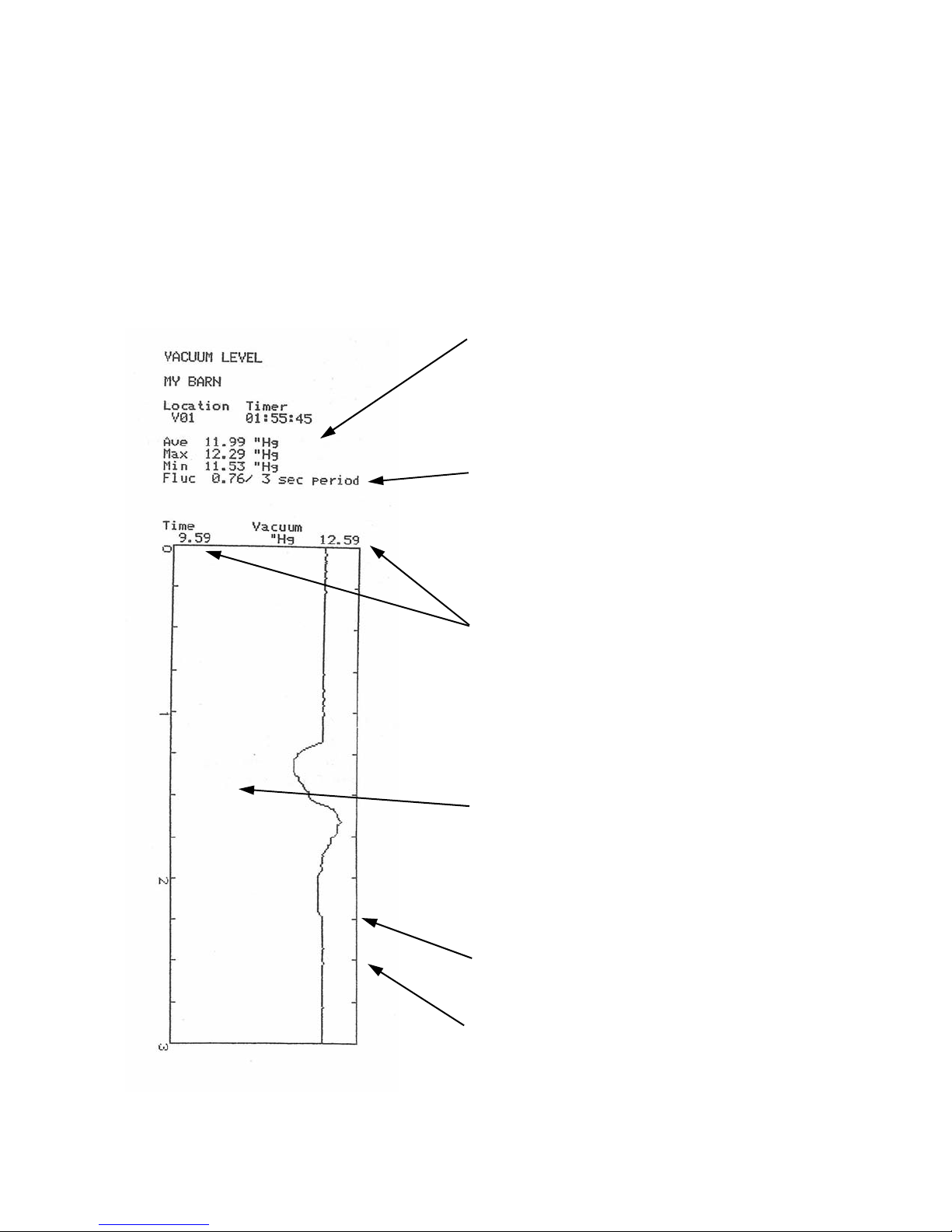
Graphs can be saved in each of the three
pneumatic functions; Vacuum Level,
Pulsator Ratio and Milk/Rest Ratio. To print
the graphs to the Digimet printer use the
item 3 Print Graph in the Utility Menu.
A Vacuum Level graph and associated
numeric data is shown below:
The numeric data is listed in the same manner
as the Vacuum Level print-out data on the
previous page.
Note: This graph has a 3 second Fluctuation time
frame and also a 3 second graph. It is not
mandatory that this be done in this manner but it
is recommended, because the Min, Max and
Fluc. figures will then directly be represented
in the graph.
At the top of the graph there are two vacuum
level figures. They represent the span of the
graph ie the minimum vacuum level that can be
represented on the graph and the maximum level
that can be represented on the graph. These
figures are not the min. and max .of the data.
Vacuum Level graphs will indicate a minimum
span of 3 ”Hg or its kPa equivalent if the min.
and max. vacuum levels are within a 3 inch span.
Otherwise the minimum and maximum borders
of the graph will be .3 above maximum and .3
below minimum.
Tick marks are indicated each 250 milliseconds
and each second is marked by a numeral.
The Ave. figure in Vacuum Level graphs is for
the last 500 milliseconds of the graph period
and not the average for the entire graph
period.
44
Page 45
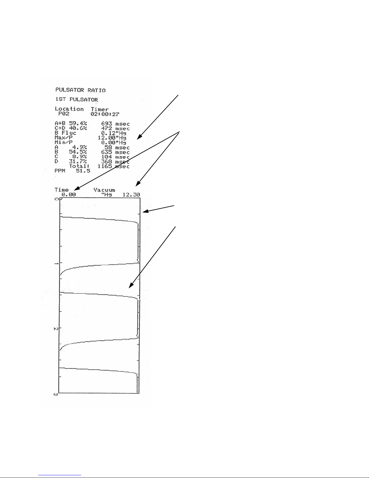
A Pulsator Ratio graph and associated
numeric data is shown below:
The numeric data is listed in the same manner
as the Pulsation Ratio print-out data on the
previous page.
The minimum and maximum borders of the
graph are indicated at the top. The maximum
border will be .3” Hg above the maximum
obtained vacuum level. If the minimum goes to
0.00 then the minimum border will be 0.00.
Otherwise, the minimum will be .3”Hg lower than
the minimum obtained vacuum level.
Tick marks are indicated each 250 milliseconds
with each second indicated by a numeral.
Note: The numeric data at the top of the
print-out, A+B, C+D etc. is calculated from
the last complete waveform which appears
on the graph. This means that if part of the last
pulsation waveform is cut-off then the numbers
represent the complete waveform preceding it.
Since there is no Fluctuation time frame in the
Pulsator Ratio function it is not necessary to
match the Fluctuation time frame from the
Vacuum Level function with the graph period
desired for Pulsator Ratio graphs.
45
Page 46
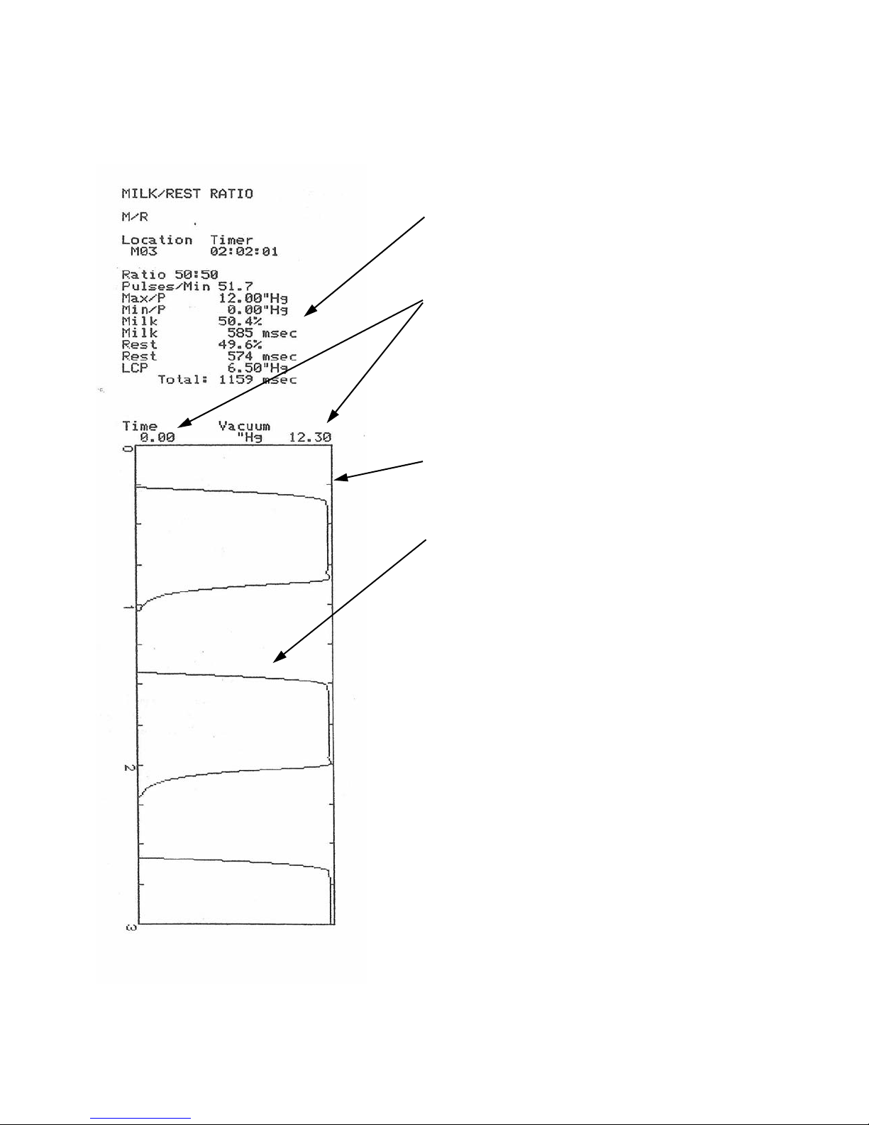
A Milk/Rest Ratio graph and associated
numeric data is shown below:
The numeric data is listed in the same manner
as the Milk/Rest Ratio print-out data on the
previous page.
The minimum and maximum borders of the
graph are indicated at the top. The maximum
border will be .3” Hg above the maximum
obtained vacuum level. If the minimum goes to
0.00 then the minimum border will be 0.00.
Otherwise, the minimum will be .3”Hg lower
than the minimum obtained vacuum level.
Tick marks are indicated each 250
milliseconds with each second indicated by a
numeral.
Note: The numeric data at the top of the
print-out, Ratio, Milk% etc. is calculated
from the last complete waveform which
appears on the graph. This means that if part
of the last pulsation waveform is cut-off then
the numbers represent the complete waveform
preceding it.
Since there is no Fluctuation time frame in the
Milk/Rest Ratio function it is not necessary to
match the Fluctuation time frame from the
Vacuum Level function with the graph period
desired for Milk/Rest Ratio graphs.
46
Page 47
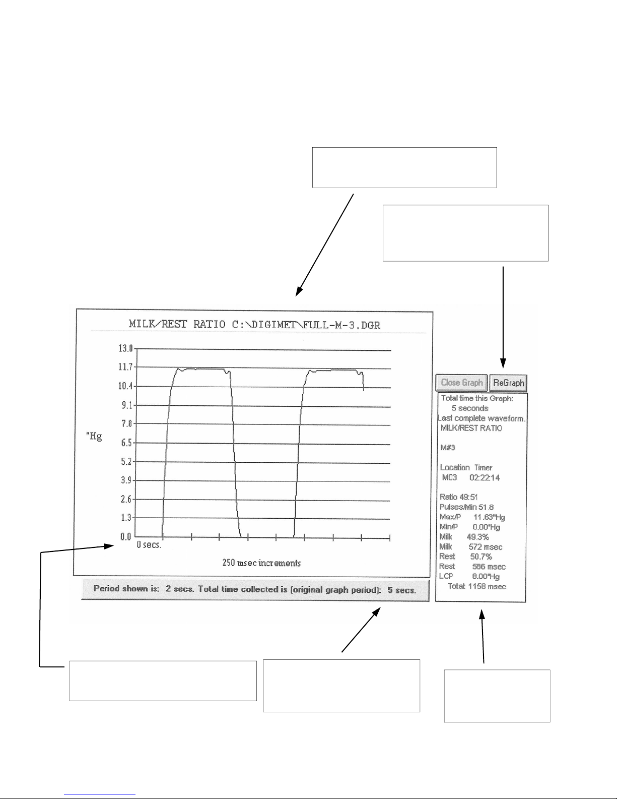
Graphs - computer
Graphs can be saved and/or printed
from the DigiData Windows program in
a couple of ways. Use Print Graph,
which is a menu item under the File
heading, to print viewed graphs, or save
a graph as a bitmap file (.bmp) to view
in other programs or print from other
programs.
The graph below is a representation of
a viewed and/or printed graph in the
DigiData computer program:
Heading consists of the function
and the saved file name.
If graph parameters are
changed, Regraph will show
the new look of the graph.
Start time is indicated and
increments are 250 milliseconds.
Period of graph shown and
original recorded graph
period are indicated.
47
Associated data
calculations are
printed here.
Page 48

Quick Reference Guide for the
Digimet 3000
1. View data real-time - Press On/Off key, then use
arrow keys to choose function, press the Enter key at
the desired function, view all data by scrolling with
arrow keys.
2. STORE (numeric data) - From function, press Menu
key to enter OPTION MENU. Use arrow keys to choose
the Store choice in the Menu. Press the Enter key and
STORE screen will appear. Choose desired storage slot
by using arrow keys. Press the Enter key. Choose a
label or don’t choose a label, then press the Menu key.
Item is stored.
3. PRINT (numeric data) - Printing single item: From
OPTION MENU use arrow keys to choose Print/Upload
choice and press Enter. The PRINT screen will appear.
Use arrow keys to choose item to print. Press the Enter
key. Next screen indicates which slot will be sent to the
printer. Make sure the Digimet Printer is hooked up and
ON. Press the Enter key. Item will Print. Printing all
numeric data: Use arrow keys to go to item 5 in the
Function Menu - the Utility Menu and press Enter. You
will be at item 1 Upload-Print all Data. Make sure the
Digimet Printer is hooked up and ON. Press the Enter
key. All items will Print.
4. STORE (graph) - In any pneumatic function go to
OPTION MENU by pressing the Menu key when in the
function. Use arrow keys to choose the Store Graph
choice in the Menu and press Enter. The GRAPH
storage screen will appear. Use arrow keys to choose
slot. Press the Enter key and choose label or don’t
choose a label. Press the Menu key. Next screen will
indicate number of seconds to graph. Use arrow keys to
choose seconds. Press the Enter key. Storage for the
amount of seconds chosen will begin. When blinking R
disappears, storage is complete.
5. PRINT (graph) - Use arrow keys to go to item 5 in
the Function Menu - the Utility Menu. Press the Enter
key then use arrow keys to choose item 3 Print Graph.
Press the Enter key and choose item to graph with
arrow keys. Press the Enter key. Screen will appear
indicating “Press Enter to start graphing. Menu to exit.”
Be sure Digimet Printer is ON. Then, press the Enter
key. Printing of the graph will begin.
6. UPLOAD (numeric data - single item) - Go to the
OPTION MENU in any of the functions and use the
arrow keys to choose the Print/Upload choice in the
Menu. Press the Enter key and the PRINT screen will
appear. Choose the item to Upload. Press the Enter key
and the next screen will indicate the slot that will be
uploaded. Make sure the DIGIMET DigiData
WINDOWS program is running and the Digimet is
hooked up via the 6 foot computer cable to the
computers serial port. On the computer display, click on
the Upload Item command button upper right corner.
This prepares the computer to accept the transmission
from the Digimet. The Digimet still indicates the Send
Slot screen. Press the Enter key on the Digimet. When
the OPTIONS MENU reappears the transmission is
Done. Click the Done Upload Item command button in
the upper right corner of the computer screen. Item has
been uploaded. To save data in a computer file, click
File - Save As, then click Save As (data, archive files),
then choose file name. Remember to save Digimet data
files with a .dm3 ending. Then click OK. File is saved.
7. UPLOAD (numeric data - all) - Go to item 1 Upload-Print
all Data in the UTILITY MENU. Make sure the DIGIMET
DigiData WINDOWS program is running and the Digimet is
hooked up via the 6 foot computer cable to the computers
serial port. On the computer screen, click on the Upload All
command button upper right corner. The caption on the button
will change to Press Enter-Digimet. Press the Enter key on
the Digimet. The caption on the button on the DigiData screen
will change to Uploading. When the computer and Digimet
are done uploading, the computer program will beep and the
caption on the button will change to Press here-Done. Press
the button and the Digimet 3000 data will appear in its
respective slots in the DigiData computer program.
Note: If you are uploading just a few items, for example, 2
Vacuum Level items, you may need to press the Enter key a
few times to get the button to change from Press Enter-
Digimet to Uploading.
To save data in a computer file, click File - Save As, then click
Save As (data, archive files), then choose file name.
Remember to save Digimet data files with a .dm3 ending.
Then click OK. File is saved
.
8. UPLOAD (graph) - Connect the 6 foot serial cable to the
Digimet and the computers serial port and open the Digidata
program.
Go to the UTILITY MENU item 2 Upload Graphic Data on the
Digimet. Press Enter on the Digimet. Choose your Graph to
upload on the Digimet. Press Enter on the Digimet, one time.
Press the Upload Graph button on the Digidata computer
screen, the button will change to “Press Digi then Here”.
Press Enter on the Digimet one more time. Then press the
“Press Digi then Here” button on computer screen. The button
changes to “******Uploading.” As uploading is taking place this
button will change to “*****Still Uploading”. When uploading is
completed the button will say “*Done Uploading”.
The Save Graphic file window will then appear. Choose a
name for your graph file and be sure it ends with .dgr. Press
the OK button in the Save Graphic files window. Your graphic
file has been uploaded from the Digimet and saved as a
computer file.
48
Page 49

The Digimet Printer unit consists of the printer and power supply. The paper roll and
printer ribbon are stored within the printer enclosure.
Digimet Printer to be used with the Digimet 3000
The printer must be connected to a power source (120 VAC) to function.
To turn the printer on – press the ON button (ON button blinks green).
To turn the printer off – press and hold the OFF button until the FEED button blinks red.
(the button blinks once, quickly)
When printing, the ON button appears solid green.
After printing, the FEED button will need to be pressed to see all that has printed.
Note: If, when initiating printing, nothing happens, do one or all of the following: 1) Make
sure there is saved data in the Digimet 2) Make sure the Digimet Printer is ON 3) Make
sure the connector at the Digimet and at the Digimet Printer are snug 4) Turn off the
Digimet Printer and the Digimet and start over.
To open the printer to change paper or to change the print ribbon, lift the top cover up.
To close, lower the top cover and press slightly forward to close completely.
Paper rolls are 2 ¼ inch (57 mm) wide and are adding machine paper rolls. If the roll is
too tight in the printer compartment it might be necessary to remove some of the paper
from the roll.
The print ribbon is an Epson HX-20 cartridge ribbon. These can be obtained from LJE
or a local stationary/computer store.
To run a printer test, turn off the printer then press the FEED button and the ON button
at the same time. When the printer stops printing the first time while running the printer
test, press the FEED button, again. The instructions to do so appear below the tear
edge of the printer.
Note: When the unit is plugged into a power source the Mode button will be green
whether or not the unit is ON or OFF. To determine whether or not the unit is on, press
the FEED button. If the printer feeds paper, unit is ON, if not, the unit is OFF.
49
Page 50
Phone: (714) 848-8001
FAX: (714) 848-0973
18192 GOTHARD STREET • HUNTINGTON BEACH, CA 92648
1. LIMITED WARRANTY: Seller warrants that the goods delivered shall be free from defects in
material and workmanship for a period of one (1) year from the date of Seller’s shipment. Seller’s sole
obligation and Buyer’s exclusive remedy for defects in the goods shall be limited, at Seller’s option, to
either repair or replacement of goods determined to be defective. Transportation and any other
delivery costs to return defective goods to Seller for repair or replacement shall be the responsibility of
Buyer. Any claim by Buyer must be made by Buyer to Seller in writing within five (5) days of the
discovery of the claimed defect but in no event after the expiration of one (1) year from the date of
Sellers’s shipment, whichever is less. Buyer’s failure to so notify Seller of such defects within the
above time periods shall bar Buyer from any remedy under this Warranty, or for recovery of damages
or losses due to defects in the goods. Any return of goods shall be subject to the prior written approval
of Seller.
THIS WARRANTY IS THE SOLE WARRANTY COVERING THE GOODS AND SELLER MAKES NO
OTHER WARRANTY OF ANY KIND, WHETHER EXPRESS, IMPLIED OR STATUTORY, AND ALL
IMPLIED WARRANTIES OF MERCHANTABILITY AND FITNESS FOR A PARTICULAR PURPOSE
ARE HEREBY DISCLAIMED BY SELLER AND EXCLUDED FROM THIS WARRANTY. IN NO
EVENT SHALL SELLER BE LIABLE FOR CONSEQUENTIAL, COMPENSATORY, PUNITIVE OR
INCIDENTAL DAMAGES HOWSOEVER ARISING FROM SELLER’S PERFORMANCE OF THIS
CONTRACT OR THE PERFORMANCE OF THE GOODS.
This Warranty shall not apply to goods which have been repaired or altered by other than authorized
representatives of Seller or to damage or defects caused by accident, vandalism, Acts of God, erosion,
normal wear and tear, improper selection by Buyer or others, and other causes beyond Seller’s control.
This Warranty shall not apply to the misapplication, improper installation, or misuse of the goods
caused by variations in environment, the inappropriate extrapolation of data provided, the failure of
Buyer or others to adhere to pertinent specifications or industry practices, or otherwise.
2. LIMITATION OF SELLER’S LIABILITY:
Seller’s liability on any claim of any kind, including claims
based upon Seller’s negligence, breach of contract, or strict liability in tort, for any loss or damage
arising out of, connected with, or resulting from the use of the goods furnished hereunder or Seller’s
performance of this contract, shall in no case exceed the purchase price allocable to the goods or part
thereof which give rise to the claim. IN NO EVENT SHALL SELLER BE LIABLE FOR SPECIAL,
INCIDENTAL, OR CONSEQUENTIAL DAMAGES HOWSOEVER ARISING OUT OF SELLER’S
PERFORMANCE OF THIS CONTRACT AND NOTWITHSTANDING WHETHER SELLER MAY HAVE
BEEN ADVISED OR IS ADVISED OF THE POSSIBILITY OF SPECIAL (OR LIQUIDATED)
DAMAGES.
50
Page 51

18192 Gothard Street
Huntington Beach, CA 92648 USA
(714) 848-8001
Toll-Free in the USA 1-800-635-6413
FAX: (714) 848-0973
E-Mail: [email protected]
Web site:
http://www.sentinelproducts.com
51
Page 52

DIGIMET
®
PEACEKEEPER
www.sentinelproducts.com
™
 Loading...