

Page 1
1
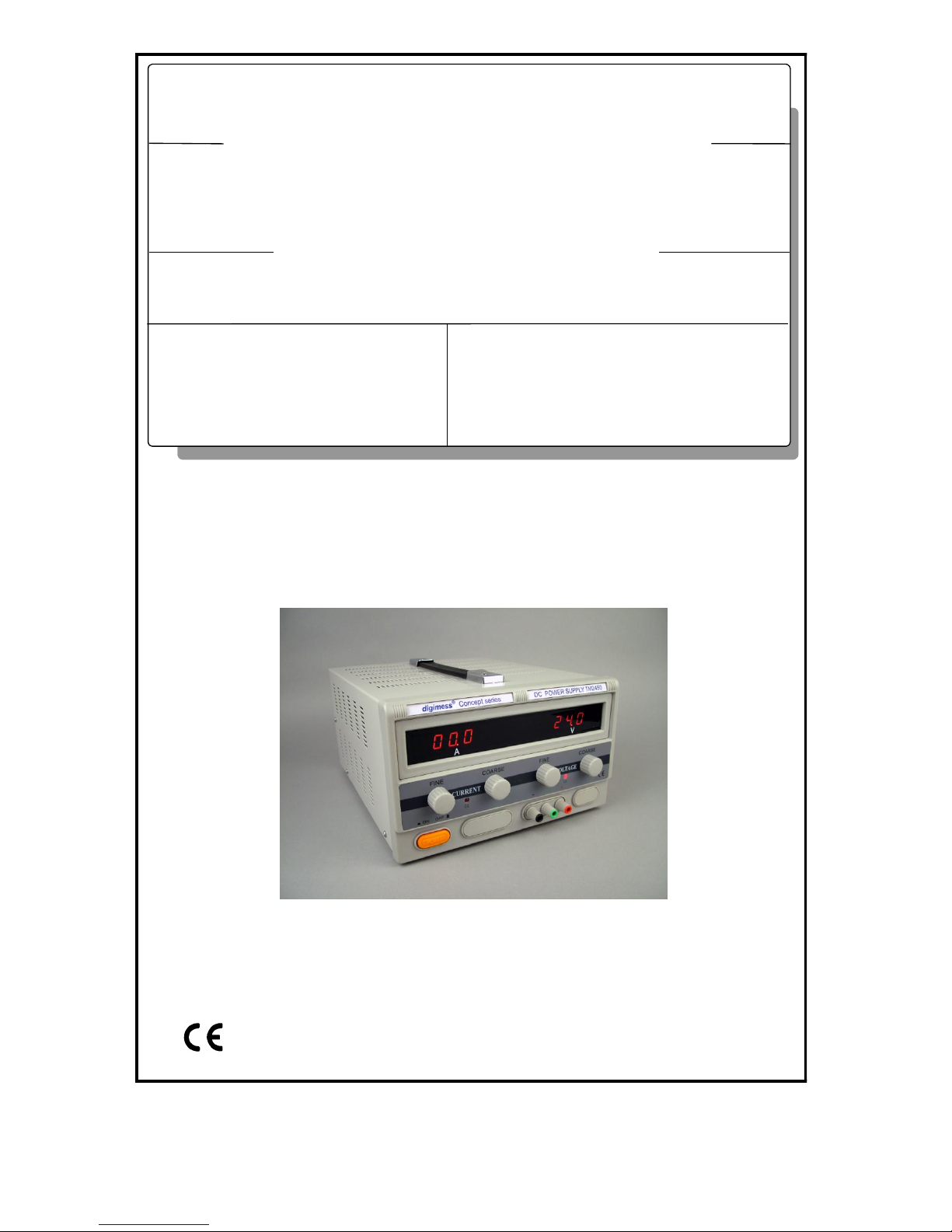
TM2450 HUC 49-01
TM1580 HUC 49-02
TM10100 HUC 49-03
digimess®
GEBRAUCHSANWEISUNG
OPERATING INSTRUCTIONS
Bestell-Nr.
Order No.
NETZEIL
POWER SUPPLY
TM SERIES
Page 2

2
Copyright 2009
Änderungen und Irrtümer vorbehalten.
Nachdruck, auch auszugsweise, nur mit schriftlicher Genehmigung des Herstellers.
Alle Rechte vorbehalten.
Subject to alterations, errors excepted.
Reprints, also in extracts, are only allowed with written permission of the manufacturer.
All rights reserved.
Page 3

3
TM Series Power Supplies
Operating Instructions
1.0 Mains Connection
The design of the unit meets the requirements of safety class I according to EN 61010-1, i.e. all metal parts
accessible from outside and exposed to contact are connected with the protective conductor of the supply
network.
Power is supplied via a mains cable with earthing contact.
1.1 Installing the power supply
The power supply should not be operated close to equipment that develops heat. To protect the power supply
from thermal overload the air vents must not be covered and a free space of about 10 cm should be ensured.
1.2 Switching on
The power supply is switched on using the power switch at the front. The power switch separates the unit
completely from the primary side of the transformer. Refer to para 3.1 and 3.2 for correct mains voltage and
fuse settings.
1.3 EMC
The power supply is interference-free according to EN 50081-1 and EN 50081-2. In order to fulfil the limit
values in line with present standards, it is absolutely necessary that only cables which are in perfect condition be connected to the unit.
1.4 Inspection and Maintenance
If service is needed, due attention should be paid to the regulations according to VDE 0701. The power supply should only be repaired by trained personnel.
Page 4

4
1.5 Warranty
The perfect working order of the power supply is guaranteed for 12 months as from delivery.
There is no warranty for faults arising from improper operation or from changes made to the power supply or
from inappropriate application.
If a fault occurs please contact or send your power supply to:
The power supply should be sent in appropriate packing - if possible in the original packing. Please enclose a
detailed fault report (functions working incorrectly, deviating specifications and so on) including unit type
and serial number.
Would you also kindly verify warranty cases by enclosing your supply delivery note. Any repairs carried out
without reference to a valid warranty will initially be at the owner’s expense.
Should the warranty have expired, we will, of course, be glad to repair your power supply as per our General
Terms Of Assembly And Service.
1.6 Description
The digimess® TM series is a comprehensive range of general purpose switch mode power supply units. All
models can operate in either constant voltage or constant current modes and feature large red LED displays
for ease of viewing.
2 Technical Data
2.1 General Data
Nominal temperature: + 23 °C 1 °C
Operating temperature: + 5°C to + 40 °C
Relative humidity: 20 to 80 %
Atmospheric pressure: 70 to 106 kPa
Operating position: horizontal or inclined by 15 °
Operating voltage: sinusoidal alternating voltage (distortion factor < 5 %)
115/230 V (+ 10 %/ 15 %)
Frequency: 50 to 60 Hz ( 5 %)
Safety class: 1, according to EN 61010 Part 1
Radio interference suppression: EN 55011 Class B
Agents details :
Page 5
5
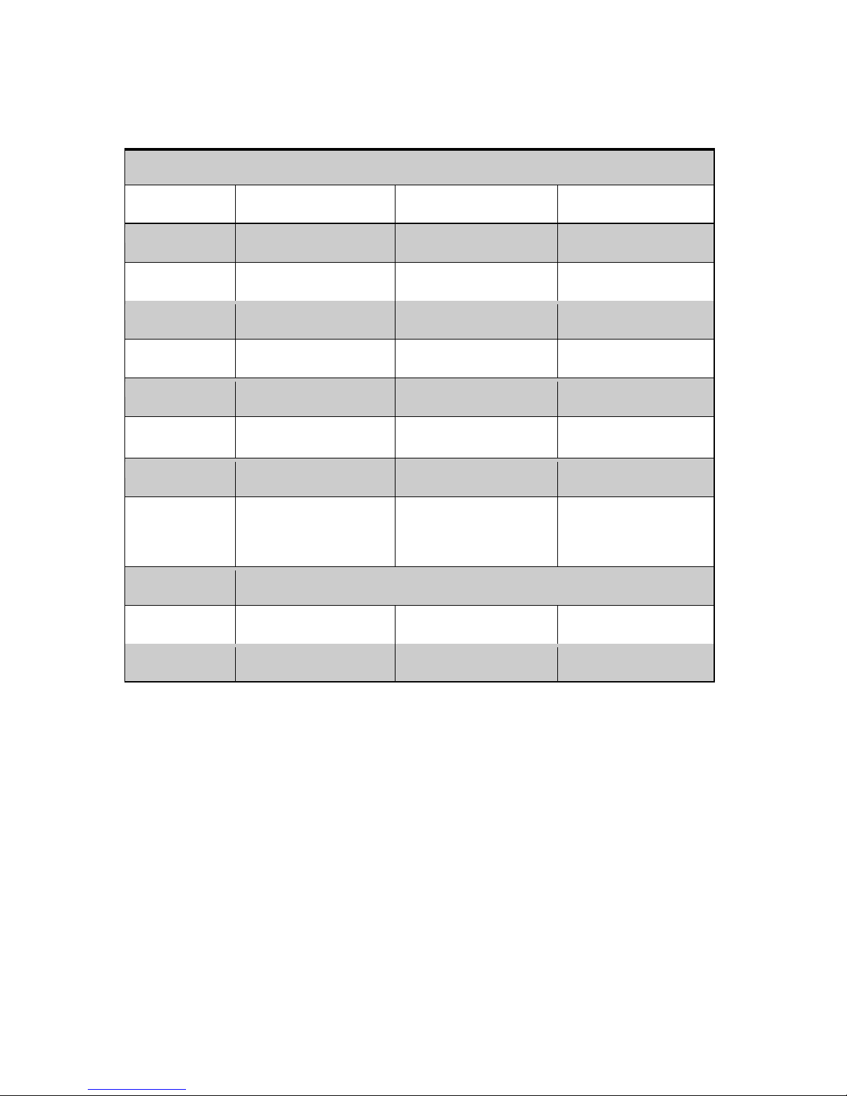
2.2 Specifications
Specification
Model No
TM2450
TM1580
TM10100
Order No
HUC49-01
HUC49-02
HUC49-03
No of outputs
Single
Single
Single
Output voltage
0-24V
0-15V
0-10V
Output current
0-50A
0-80A
0-100A
Line regulation
<15mV
<15mV
<15mV
Load regulation
<50mV
<45mV
<70mV
Ripple & noise
<5mVrms
<7mVrms
<10mVrms
Display
2 x 3.5 digit LED
Accuracy :
V - 1.0% + 2 dig
I - 2.0% + 2 dig
2 x 3.5 digit LED
Accuracy :
V - 1.0% + 2 dig
I - 2.0% + 2 dig
2 x 3.5 digit LED
Accuracy :
V - 1.0% + 2 dig
I - 2.0% + 2 dig
Input voltage
110/220V +/- 10% AC (external selector switch)
Dimensions
365 x 265 x 164mm
415 x 265 x 164mm
415 x 265 x 164mm
Weight
7.0kg
7.8kg
7.8kg
Page 6

6
3.0 Operating instructions
3.1 Mains input
The mains input connector is located on the rear of the unit. Before connecting to the mains supply the user
should verfy that the unit is set to the correct voltage for the country of use. The mains voltage is set by the
external mains voltage selector switch located on the rear of the unit.
3.2 Mains input fuse
The mains fuse is located on the rear of the unit. The correct fuse for each supply voltage is as follows :
Model 110Vac 220Vac
TM2450 T30A 250V T15A 250V
TM1580 T30A 250V T15A 250V
TM10100 T25A 250V T15A 250V
3.3 Power on/off
The mains power to the unit is switched on and off using the POWER on/off pushbutton.
3.4 Voltage and current display
TM2450, TM1580 and TM10100 feature independent displays for both output voltage and output current.
3.5 Output terminals
All units have two sets of output terminals. For output currents exceeding 20A the terminals on the rear panel must be used.
3.6 Output voltage and output current
The output voltage is adjusted to the desired value using both the Coarse and Fine Voltage controls. The
output current level is adjusted to the desired value usng both the Coarse and Fine Current controls. If the
output current exceeds the set current value the power supply will limit the output current to the set value.
3.7 Caution
In the event of a short circuit at the output the current will limit at the value set by the current controls, however the unit should be turned off and the short circuit removed before continuing use.
Page 7

7
Netzteile der Serie TM
Bedienungsanweisung
1.0 Netzanschluss
Das Design des Netzteils erfüllt die Anforderungen der Schutzklasse I gemäß EN 61010-1, d.h. alle
Metallteile, die von außen zugänglich sind und berührt werden können, sind mit dem Schutzleiter des
Zufuhrnetzes verbunden.
Die Stromzufuhr erfolgt über ein Netzkabel mit Erdkontakt.
1.1 Installation des Netzteils
Das Netzteil sollte nicht in Nähe von wärmeentwickelnden Einrichtungen operiert werden. Zum Schutz des
Netzteils vor thermischer Überlastung dürfen die Luftschlitze nicht bedeckt sein und ein Spielraum von ca.
10 cm sollte gewährleistet sein.
1.2 Einschalten
Das Netzteil wird mit dem Stromschalter vorne eingeschaltet. Der Stromschalter trennt die Einheit völlig
von der Primärseite des Transformators. Siehe Paragr. 3.1 und 3.2 für korrekte Netzspannung und
Sicherungseinstellungen.
1.3 EMV
Das Netzteil ist gemäß EN 50081-1 und EN 50081-2 entstört. Zur Erfüllung der Grenzwerte entsprechend
der geltenden Normen ist es unbedingt notwendig, dass nur Kabel in perfektem Zustand an die Einheit
angeschlossen werden.
1.4 Inspektion und Wartung
Wenn Wartungsarbeiten notwendig sind, dann sollten die Vorschriften gemäß VDE 0701 entsprechend
beachtet werden. Das Netzteil darf nur von fachlich ausgebildetem Personal repariert werden.
Page 8

8
1.5 Garantie
Die perfekte Funktion des Netzteils wird für einen Zeitraum von 12 Monaten ab Lieferung garantiert.
Die Garantie gilt nicht für Fehler infolge unsachgemäßer Operation oder am Netzteil vorgenommenen
Änderungen oder unsachgemäßer Anwendung.
Das Netzteil sollte in geeigneter Verpackung - wenn möglich in der Originalverpackung versandt werden.
Bitte legen Sie einen detaillierten Fehlerbericht (inkorrekt arbeitende Funktionen, Abweichung von
Spezifikationen und so weiter) sowie Einheitstyp- und Seriennummer bei.
Wir bitten Sie zudem, den Garantieanspruch durch Beilegen Ihres Lieferscheins zu bestätigen. Alle
Reparaturen, die ohne Bezugnahme auf eine gültige Garantie stattfinden, erfolgen zunächst zu Kosten des
Besitzers. Falls die Garantie abgelaufen ist, dann sind wir selbstverständlich gerne bereit, Ihr Netzteil gemäß
unserer Allgemeinen Montage- und Servicebedingungen zu reparieren.
1.6 Beschreibung
Bei den Geräten der digimess® Serie TM handelt es sich um allgemein einsetzbare, schaltbare Netzteile mit
hohen Ausgangsströmen. Alle Modelle können in den Betriebsarten Konstantspannung oder Konstantstrom
arbeiten und besitzen zur einfachen Ablesung große, rote LED-Displays
2 Technische Daten
2.1 Allgemeine Daten
Nenntemperatur: + 23 °C 1 °C
Betriebstemperatur: + 5°C bis + 40 °C
Relative Feuchtigkeit: 20 bis 80 %
Atmosphärischer Druck: 70 bis 106 kPa
Betriebsposition: horizontal oder um 15 ° geneigt
Betriebsspannung: sinusförmige Wechselspannung (Verzerrungsfaktor < 5 %)
115/230 V (+ 10 %/ 15 %)
Frequenz: 50 bis 60 Hz ( 5 %)
Schutzklasse: 1, gemäß EN 61010 Teil 1
Funkentstörung: EN 55011 Klasse B
Händlerdetails :
Page 9

9
2.2 Spezifikationen
Technische Daten
Modell-Nr.
TM2450
TM1580
TM10100
Bestell-Nr.
HUC49-01
HUC49-02
HUC49-03
Anz. der Ausgänge
Einer
Einer
Einer
Ausgangsspannung
0-24 V
0-15 V
0-10 V
Ausgangsstrom
0-50 A
0-80 A
0-100 A
Leitungsregelung
<15 mV
<15 mV
<15 mV
Lastregelung
<50 mV
<45 mV
<70 mV
Brummen u.
Rauschen
<5 mV effektiv
<7 mV effektiv
<10 mV effektiv
Display
2 x 3,5 stell. LED
Genauigkeit :
V – 1,0 % + 2 St.
I – 2,0 % + 2 St.
2 x 3,5 stell. LED
Genauigkeit :
V – 1,0 % + 2 St.
I – 2,0 % + 2 St.
2 x 3,5 stell. LED
Genauigkeit :
V – 1,0 % + 2 St.
I – 2,0 % + 2 St.
Eingangsspannung
110/220 V +/-10 % WS (externer Wählschalter)
Abmessungen
365 x 265 x 164 mm
415 x 265 x 164 mm
415 x 265 x 164 mm
Gewicht
7.0 kg
7.8 kg
7.8 kg
Page 10

10
3.0 Betriebsanweisung
3.1 Netzeingabe
Der Netzeingabeanschluss befindet sich hinten an der Einheit. Vor Anschluss an die Netzzufuhr sollte der
Verwender prüfen, dass die Einheit auf die jeweils für das Land korrekte Spannung eingestellt ist. Die
Netzspannung wird durch den externen Netzspannungsschalter hinten an der Einheit eingestellt.
3.2 Netzeingabesicherung
Die Netzsicherung befindet sich hinten an der Einheit. Die korrekte Sicherung für jede Netzspannung ist
folgende :
Modell 110V WS 220 V WS
TM2450 T30A 250V T15A 250V
TM1580 T30A 250V T15A 250V
TM10100 T25A 250V T15A 250V
3.3 Strom ein/aus
Die Netzzufuhr zur Einheit wird mit der Drucktaste POWER (STROM)-Ein/Aus ein- und ausgeschaltet.
3.4 Spannungs- und Stromanzeige
TM2450, TM1580 und TM10100 - haben für die Spannungs- und Stromausgabe unabhängige Displays.
3.5 Ausgangsanschlüsse
Alle Einheiten haben zwei Sätze Ausgangsanschlüsse. Für den Ausgangsstrom der das 20A übersteigt, die
Terminale auf der Rückwand müssen benutzt werden.
3.6 Ausgangsspannung- und Ausgangsstrom
Die Ausgangsspannung wird durch Verwendung der Spannungssteuerungen 'Coarse' (Grob) und 'Fine'
(Fein) auf den gewünschten Wert eingestellt. Der Ausgangsstrom wird durch Verwendung der
Stromsteuerungen 'Coarse' und 'Fine' auf den gewünschten Wert eingestellt. Wenn die Ausgabe den
eingestellten Stromwert überschreitet, dann beschränkt das Netzteil den Ausgangsstrom auf den eingestellten
Wert.
3.7 Vorsicht
Im Falle eines Kurzschlusses an der Ausgabe wird der Strom auf den durch die Stromregelungen
eingestellten Wert beschränkt, wobei die Einheit jedoch ausgeschaltet und der Kurzschluss beseitigt werden
sollte, bevor die Einheit weiter verwendet wird.
Page 11

11
digimess
®
Konformitatserklarung
Declaration of Conformity / Declaration de Conformite
CE
Der Hersteller/importeur
The manufacturer/importer
Le producteur/importateur
Anschrift/Address/Adresse
erklart hiermit eigenverantwortlich, dass das
Produkt :
hereby declares that the product :
declare, que le produit :
Bezeichnung/Name/Description
Type/Model/Type
Bestell-Nr/Order No/No de ref
folgenden Normen entspricht :
is in accordance with the following
specifications :
correspond aux normes suivantes :
Das Produkt erfullt somit die Forderungen
folgender EG-Richtlinien :
Therefore the product fulfills the demands of
the following EC-Directives :
Le produit satisfait ainsi aux conditions des
directives suivantes de la CE :
73/23/EWG
89/336/EWG
Derby, 2.7.2009
Vann Draper Electronics Ltd
Stenson House
Stenson
Derby
DE73 1HL
ENGLAND
Netzeil
Power supply
Bloc d’alimentation
TM2450, TM1580, TM10100
HUC49-01, 49-02, 49-03
EN61010-1 (1994)
DIN EN 50081-1 (1993) DIN EN 50081-2 (1994)
EN50082
EN 55011 (1991) Class B
EN 55022 (1987) Class B
IEC 801-2 (1991)/prEN 55024-2 (1992) 2kV
IEC 801-4 (1988)/prEN 55024-4 (1993) 1kV Burst
IEC 801-3 (1984) 3V/m ; 0,15-150MHz
EN61000-3-2
EN61000-3-3
2002/95/EC RoHS
2002/96/EC WEEE
Richtlinie betreffend elektrische Betriebsmittel zur
Verwendung innerhalb bestimmter Spannungsgrenzen
Directive relating to electrical equipment designed for
use within certain voltage limits
Directive relatives au materiel electrique destine a etre
employe dans certaines limites de tension
Richtlinie uber die elektromagnetische Vertraglichkeit
Directive relating to electromagnetic compatibility
Directive relatives a la compatibilitie electromagnetique
…………………………..
A.P. Smith
Leiter Qualitatsmanagement
Quality Manager/Directeur Controle de Qualite
 Loading...