

digimess DS25 User Manual

DS25 Colour Digital Storage Oscilloscope User Manual
1
digimess
®
DS25
Portable Colour Digital Storage Oscilloscope
User's Manual

DS25 Colour Digital Storage Oscilloscope User Manual
2
www.digimessinstruments.co.uk

DS25 Colour Digital Storage Oscilloscope User Manual
3
Copyright 2006
Änderungen und Irrtümer vorbehalten.
Nachdruck, auch auszugsweise, nur mit schriftlicher Genehmigung des Herstellers.
Alle Rechte vorbehalten.
Subject to alterations, errors excepted.
Reprints, also in extracts, are only allowed with written permission of the manufacturer.
All rights reserved.

DS25 Colour Digital Storage Oscilloscope User Manual
4
WARRANTY
The perfect working order of the oscilloscope is guaranteed for 12 months as from delivery.
There is no warranty for faults arising from improper operation or from changes made to the
oscilloscope or from inappropriate application.
If a fault occurs please contact or send your oscilloscope to:
The oscilloscope should be sent in appropriate packing - if possible in the original packing. Please
enclose a detailed fault report (functions working incorrectly, deviating specifications and so on)
including unit type and serial number.
Would you also kindly verify warranty cases by enclosing your supply delivery note. Any repairs
carried out without reference to a valid warranty will initially be at the owner’s expense.
Should the warranty have expired, we will, of course, be glad to repair your oscilloscope as per our
General Terms Of Assembly And Service.
Agents details :

DS25 Colour Digital Storage Oscilloscope User Manual
5
Table of Contents
General Safety Requirements ______________________________________________ 7
Safety Terms and Symbols_________________________________________________ 8
General Characteristics of the DS25 Colour Digital Storage Oscilloscope __________ 9
Junior User’s' Guidebook________________________________________________ 10
Introduction to the Front Panel and the User's Interface of the DS series Oscilloscope __ 11
How to Carry out the General Inspection _______________________________________15
How to Carry out the Function Inspection ______________________________________16
How to Implement Probe Compensation________________________________________18
How to Set the Probe Attenuation Coefficient____________________________________ 19
How to Use the Probe Safely __________________________________________________ 20
How to Implement Auto-calibration____________________________________________ 21
Introduction to the Vertical System ____________________________________________22
Introduction to the Horizontal System__________________________________________ 23
Introduction to the Trigger System_____________________________________________24
Advanced User's Guidebook ______________________________________________ 25
How to Set the Vertical System ________________________________________________ 26
Implementation of Mathematical Manipulation Function__________________________ 32
Application of VERTICAL POSITION and VOLTS/DIV Knobs ____________________ 33
How to Set the Horizontal system______________________________________________ 34
Main Time Base ____________________________________________________________ 35
Window Setting_____________________________________________________________ 36
Window Expansion__________________________________________________________37
How to Set the Trigger System ________________________________________________38
Trigger Control_____________________________________________________________ 39
Edge Trigger _______________________________________________________________39
Video Trigger ______________________________________________________________ 42
How to Operate the Function Menu____________________________________________ 45
How to Implement Sampling Setup ____________________________________________ 45
How to Set the Display System ________________________________________________ 48

DS25 Colour Digital Storage Oscilloscope User Manual
6
Persist ____________________________________________________________________ 50
XY Format ____________________________________________________________________50
How to Save and Recall a Wave Form __________________________________________52
Save and Recall the Wave Form _______________________________________________53
How to Carry out the Auxiliary System Function Setting __________________________54
Do Self Cal (Self-Calibration) _________________________________________________ 55
SYS STAT (System State)_____________________________________________________55
How to Conduct Automatic Measurement_______________________________________ 57
Measure___________________________________________________________________ 57
How to Carry out Cursor Measurement ________________________________________59
Cursor Measurement________________________________________________________ 60
How to Use Executive Buttons_________________________________________________62
AUTOSET_________________________________________________________________ 62
Examples of Application _________________________________________________ 63
Example 1: Measurement of Simple Signals _____________________________________63
Example 2: Gain of the Amplifier in the Metering Circuit__________________________ 64
Example 3: Capture a Single Signal____________________________________________ 65
Example 4: Analyze the Details of a Signal ______________________________________ 67
Example 5: Application of X-Y Function________________________________________ 69
Example 6: Video Signal Trigger ______________________________________________71
Fault Treatment________________________________________________________ 73
Appendix A: Technical Specifications ______________________________________ 74
Appendix B: Enclosure __________________________________________________ 79
Appendix C: Maintenance, Cleaning and Repair _____________________________ 79

DS25 Colour Digital Storage Oscilloscope User Manual
7
General Safety Requirements
Before operating, please read the following safety precautions to avoid any
possible injury and prevent this product or any other products connected from
damage. In order to avoid any contingent danger, this product is only to be used
within the range specified.
Only qualified technicians should implement maintenance procedures.
Prevention of Fire or Bodily Injury.
Use the correct power line. Only use the power cord specially provided for this
product or one which has been approved.
Connect or Disconnect Correctly. When the probe or testing wire is connected to the
power lead, please do not connect and disconnect the probe or testing wire freely.
Product Grounding. This product is grounded through the power lead grounding
conductor. In order to prevent any electric shock, the grounding conductor must be
connected to the ground. It requires guarantee that this product has been already
grounded correctly before any connection with its input or output terminal.
Connect the probe correctly. The grounding end of the probe corresponds to the
grounding phase. Please don't connect the grounding end to the positive phase.
Pay attention to the nominal values of all terminals. In order to prevent any fire or
electric shock risks, please pay attention to all the nominal values and marks of this
product. Before implement any connections for this product, please read the user's
manual of this product to understand the information about the rated values further.
Do not operate without the instrument cover installed. If the cover or panel has
already been removed, please don't operate this product.
Use the proper fuse. Only the fuse complying with the specified type and nominal
value for this product can be used.
Avoid touching any exposed circuit. When the product is on power, please don't
touch the uncovered contacts and parts.
Please do not operate if a fault is suspected. If suspecting damage to this product,
please contact the qualified maintenance personnel for check.
Keep a good ventilation condition. Please consult the detailed installation
instruction in the user's manual so that this product can be erected correctly, keeping it
under a good ventilation condition.
Do not operate in a moist environment.
Do not operate in an explosive environment .
Keep the product’s surface clean and dry.
DS25 Colour Digital Storage Oscilloscope User Manual
8
Safety Terms and Symbols
Terms in this manual. The following terms may appear in this manual:
Warning. A warning statement indicates the conditions and actions which may
endanger the life safety.
Note. A note statement indicates the conditions and actions which may cause
damage to this product or other property.
Terms on the product. The following terms may appear on this product:
Danger: It indicates that there may be an immediate injury to you when you encounter
this mark.
Warning: It indicates that there may not be an immediate injury to you when you
encounter this mark.
Note: It indicates that there may be damage to this product or other property.
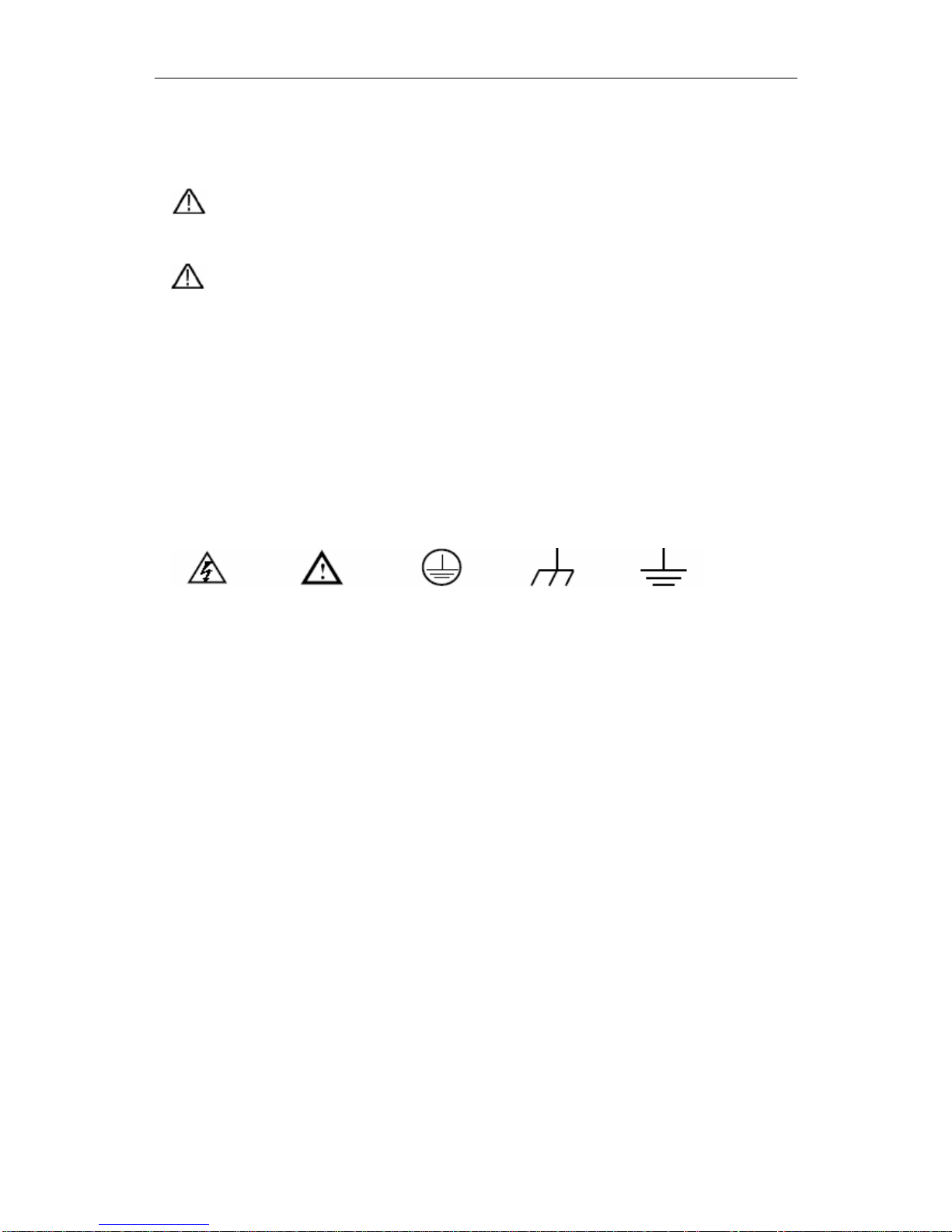
Symbols on the products. The following symbol may appear on the products:
High Voltage Please Consult the Manual. Protective Ground End Grounding End for Measurement Earth End on the Shell

DS25 Colour Digital Storage Oscilloscope User Manual
9
General Characteristics of the DS25
Colour Digital Storage Oscilloscope
Bandwidth of 25MHz;
Record length of 6,000 points for each channel;
Sampling rates of 100MS/s for each channel;
Read-out with the cursor;
Five automatic measurement functions;
Color liquid crystal display with high resolution and high contrast including
adjustable back light;
Store and recall waveforms;
Automatic setting function provides fast set up;
Multiple-waveform calculation function;
Detect average and peak values of a waveform;
Digital real-time oscilloscope;
Edge and video triggering function;
USB communication ports;
Different continuous display times;
User interface in two languages.

DS25 Colour Digital Storage Oscilloscope User Manual
10
Junior User’s' Guidebook
This chapter deals with the following topics mainly:
Introduction to the front panel and the user’s interface of the DS series oscilloscope
How to carry out general inspection
How to carry out functional inspection
How to make a probe compensation
How to set the probe attenuation coefficient
How to use the probe safely
How to implement an auto-calibration
Introduction to the vertical system
Introduction to the horizontal system
Introduction to the trigger system

DS25 Colour Digital Storage Oscilloscope User Manual
11
Introduction to the Front Panel and the User's Interface of the
DS series Oscilloscope
When you get a new-type oscilloscope, you should get acquainted with its front panel
at first and the DS series digital storage oscilloscope is no exception. This chapter
makes a simple description of the operation and function of the front panel of the DS
series oscilloscope, enabling you to be familiar with the use of the DS series
oscilloscope in the shortest time. The DS series oscilloscope offers a simple front
panel with distinct functions for completing basic operations, in which the knobs and
function pushbuttons are included. The knobs have the functions similar to other
oscilloscopes. The 5 buttons in the column on the right side of the display screen are
menu selection buttons (defined as F1 to F5 from top to bottom respectively), through
which, you can set the different options for the current menu. The other pushbuttons
are function buttons, through which, you can enter different function menus or obtain
a specific function application directly.
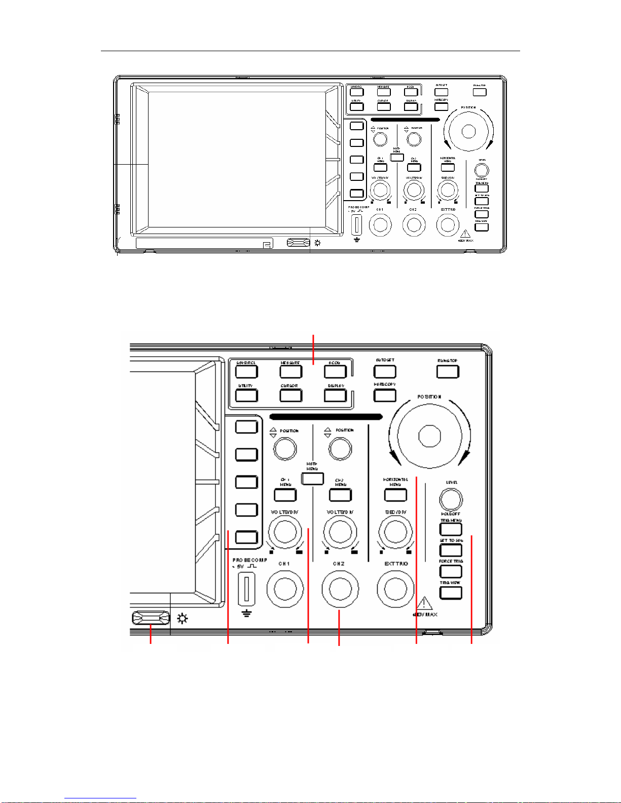
DS25 Colour Digital Storage Oscilloscope User Manual
12
Fig. 1 The Front Panel of a DS series Oscilloscope
Function Buttons
Fig. 2 Explanatory Drawing for Operation of the DS series Oscilloscope
Back-light
Adjustment
Menu Selection
Vertical Control
Connector
Horizontal
Control
Trigger
Control
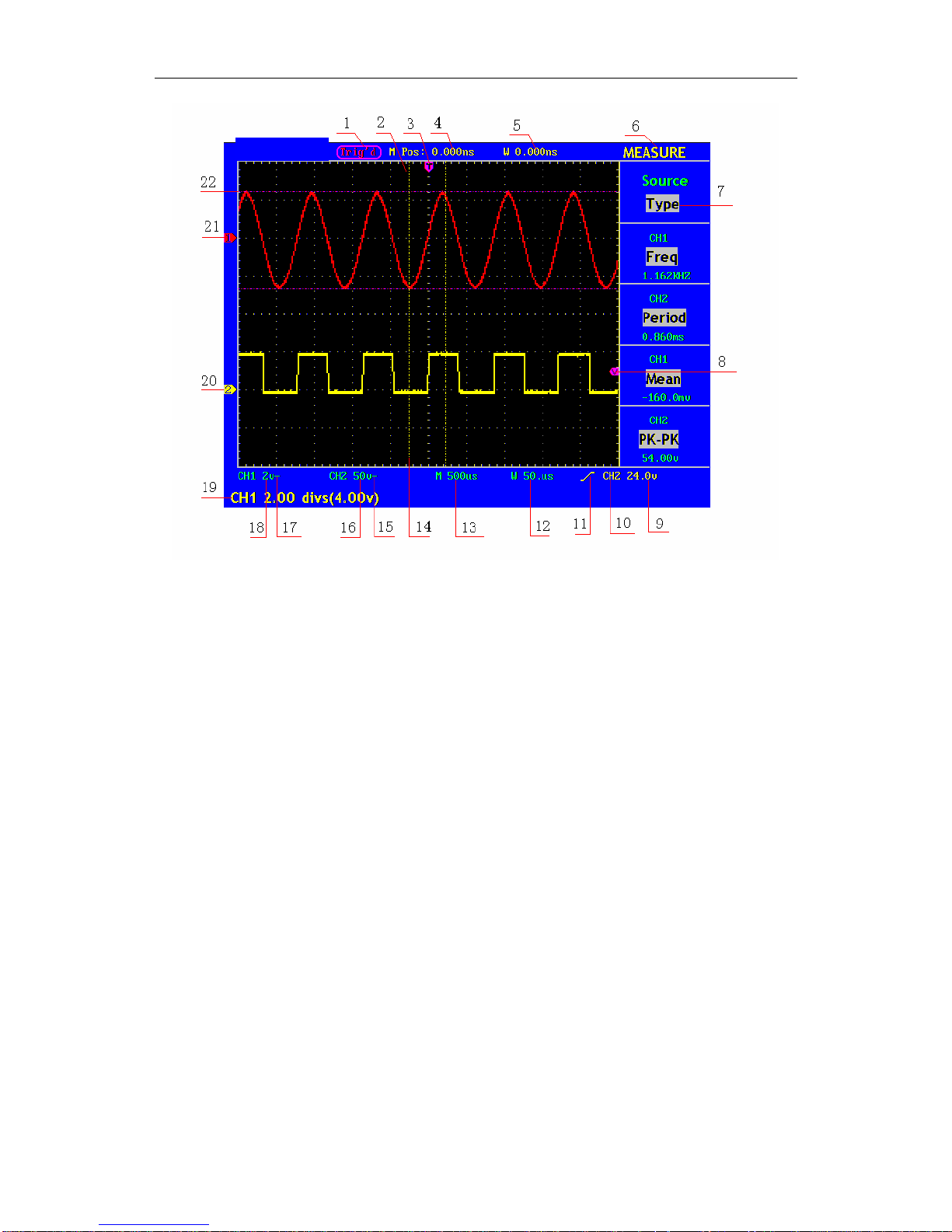
DS25 Colour Digital Storage Oscilloscope User Manual
13
Fig. 3 Illustrative Drawing of Display Interfaces
1. The Trigger State indicates the following information:
Auto: The oscilloscope is under the Automatic mode and is
collecting the waveform under the non-trigger state.
Trig' d: The oscilloscope has already detected a trigger signal and is
collecting the after-triggering information.
Ready: All pre-triggered data have been captured and the
oscilloscope has been already ready for accepting a trigger.
Scan: The oscilloscope captures and displays the waveform data
continuously in the scan mode.
Stop: The oscilloscope has already stopped the waveform data
acquisition.
2. Waveform Viewing Area.
3. The purple pointer indicates the horizontal trigger position, which can be adjusted
by the horizontal position control knob.
4. The reading shows the time deviation between the horizontal trigger position and
the screen centre line, which equals 0 in the screen center.
5. This reading shows the time deviation between the horizontal trigger position and
the window centre line, which is regarded as 0 in the window center.
6. It indicates the current function menu.
DS25 Colour Digital Storage Oscilloscope User Manual
14
7. It indicates the operation options for the current function menu, which changes
with the function menus.
8. The purple pointer shows the trigger level position.
9. The reading shows the trigger level value.
10. The reading shows the trigger source.
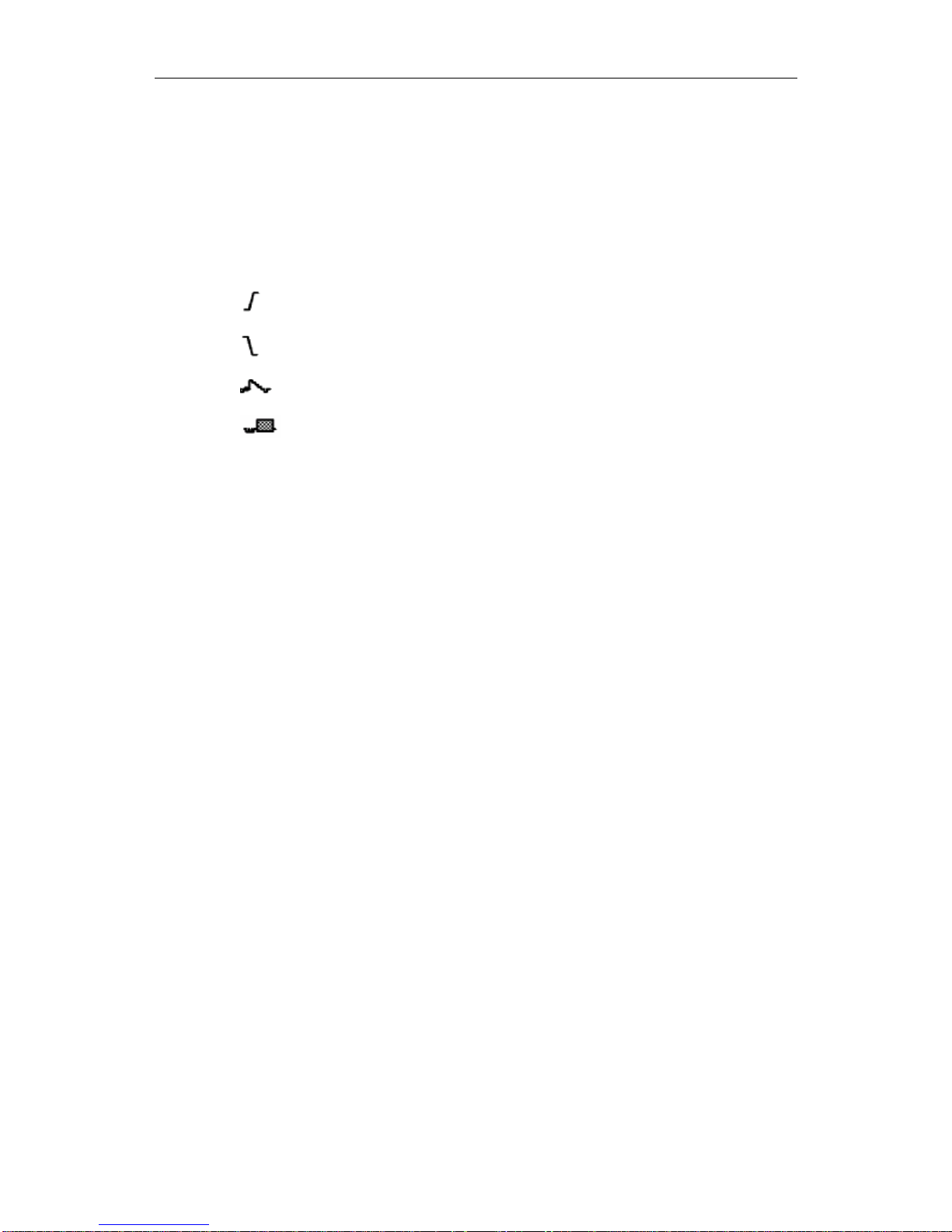
11. It shows the selected trigger type:
Rising edge triggering
Falling edge triggering
Video line synchronous triggering
Video field synchronous triggering
12. The reading shows the window time base set value.
13. The reading shows the main time base set value.
14. The two yellow dotted lines indicate the size of the viewing expanded window.
15. The icon shows the coupling mode of the CH2 channel.
“—“ indicates the direct current coupling
“ ~” indicates the AC coupling
16. The reading shows the vertical scale factor (the Voltage Division) of the CH2
channel.
17. The icon indicates the coupling mode of the CH1 channel:
The icon "–" indicates the direct current coupling
The icon "~" indicates the AC coupling
18. The reading indicates the vertical scale factor (the Voltage Division) of the CH1
channel.
19. The information shows the zero point positions of CH1 or CH2 channel.
20. The yellow pointer shows the grounding datum point (zero point position) of the
waveform of the CH2 channel. If the pointer is not displayed, it shows that this
channel is not opened.
21. The red pointer indicates the grounding datum point (zero point position) of the
waveform of the CH1 channel. If the pointer is not displayed, it shows that the
channel is not opened.
22. The positions of two purple dotted line cursors measurements.

DS25 Colour Digital Storage Oscilloscope User Manual
15
How to Carry on the General Inspection
After you receive a new DS series oscilloscope, it is recommended that you should
make a check of the instrument according to the following steps:
1. Check whether there is any damage caused by transportation.
If it is found that the packaging carton or the foamed plastic protection cushion has
suffered serious damage, do not throw it away until the complete device and its
accessories satisfy the electrical and mechanical property tests.
2. Check the Accessories
The supplied accessories have been already described in the Appendix B
“Accessories” of this Manual. You can check whether there is any loss of accessories
with reference to this description. If it is found that there is any accessory lost or
damaged, please get in touch with the distributor of digimess responsible for this
service.
3. Check the Complete Instrument
If it is found that there is damage to the appearance of the instrument, or the
instrument does not work normally, or fails in the performance test, please get in
touch with the digimess distributor responsible for this business. If there is damage to
the instrument caused by the transportation, please keep the package.
DS25 Colour Digital Storage Oscilloscope User Manual
16
How to Carry out the Function Inspection
Make a quick function check to verify the normal operation of the instrument,
according to the following steps:
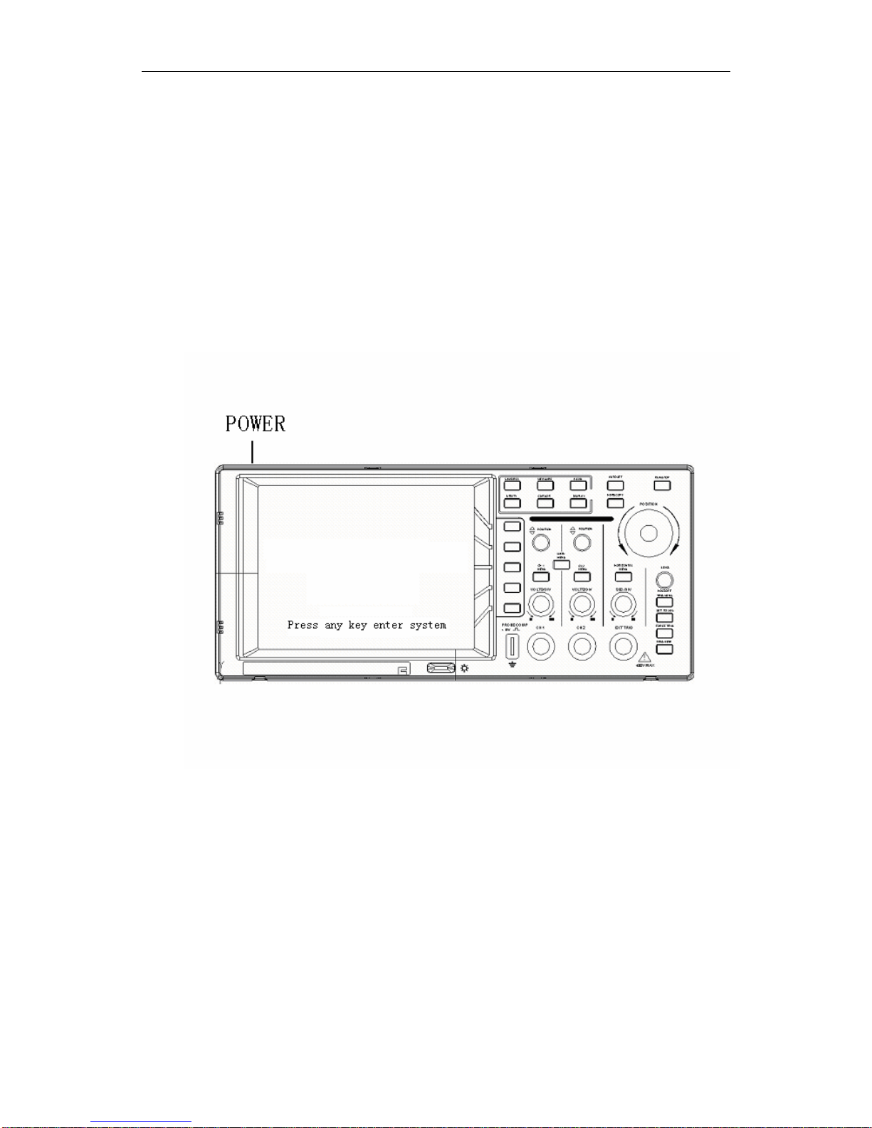
1. Connect the Instrument to the Power and Push down the Power Switch Button.
The instrument carries out all self-check items and shows the prompt “Press any Key
Enter the Operating Mode”. Press the “UTILITY” button to get access to the
“FUNCTION” menu and push down F2 the menu selection button to call out the
function “Recall Factory”. The default attenuation coefficient set value of the probe in
the menu is 10X, shown as Fig. 4.
Fig. 4 Power on the Instrument
2. Set the Switch in the Oscilloscope Probe as 10X and Connect the
Oscilloscope with CH1 Channel.
Align the slot in the probe with the plug in the CH1 connector BNC, and then tighten
the probe with rotating it to the right side.
Connect the probe tip and the ground clamp to the connector of the probe
compensator, shown as Fig. 5.
DS25 Colour Digital Storage Oscilloscope User Manual
17
Probe comp
CH1
Fig. 5 Connection of the Probe
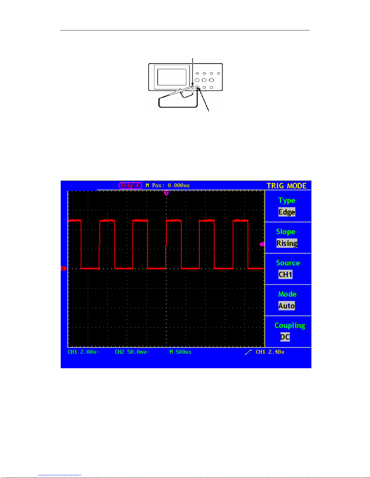
3. Press the AUTOSET Button.
The square wave of 1 KHz frequency and 5V peak-peak value will be displayed in
several seconds (see Fig. 6).
Fig. 6 Autoset
Check CH2 by repeating Step 2 and Step 3.

DS25 Colour Digital Storage Oscilloscope User Manual
18
How to Implement the Probe Compensation
When connecting the probe with any input channel for the first time, perform this
adjustment to match the probe with the input channel. A probe which is not
compensated or presents a compensation deviation will result in a measuring error or
mistake. For adjusting the probe compensation, please carry out the following steps:
1. Set the attenuation coefficient of the probe in the menu as 10X and that of the
switch in the probe as 10X, and connect the oscilloscope probe with the CH1
channel. If a probe hook tip is used, ensure that it keeps in close touch with the
probe. Connect the probe tip with the signal connector of the probe compensator
and connect the reference wire clamp with the ground wire connector of the
probe connector, and then press the button AUTOSET (see Fig. 5).
2. Check the displayed wave forms and regulate the probe till a correct
compensation is achieved (see Fig. 7 and Fig. 8).
Fig. 7 Displayed Wave Forms of the Probe Compensation
3. Repeat the steps mentioned if necessary.
Fig. 8 Adjust Probe
DS25 Colour Digital Storage Oscilloscope User Manual
19
How to Set the Probe Attenuation Coefficient
The probe has several attenuation coefficients, which will influence the vertical scale
factor of the oscilloscope.
If it is required to change (check) the set value of the probe attenuation coefficient,
press the function menu button of the channels used, then push down the selection
button corresponding to the probe till the correct set value is shown.
This setting will be valid all the time before it is changed again.
Note: The attenuation coefficient of the probe in the menu is preset to 10X when
the oscilloscope is delivered from the factory.
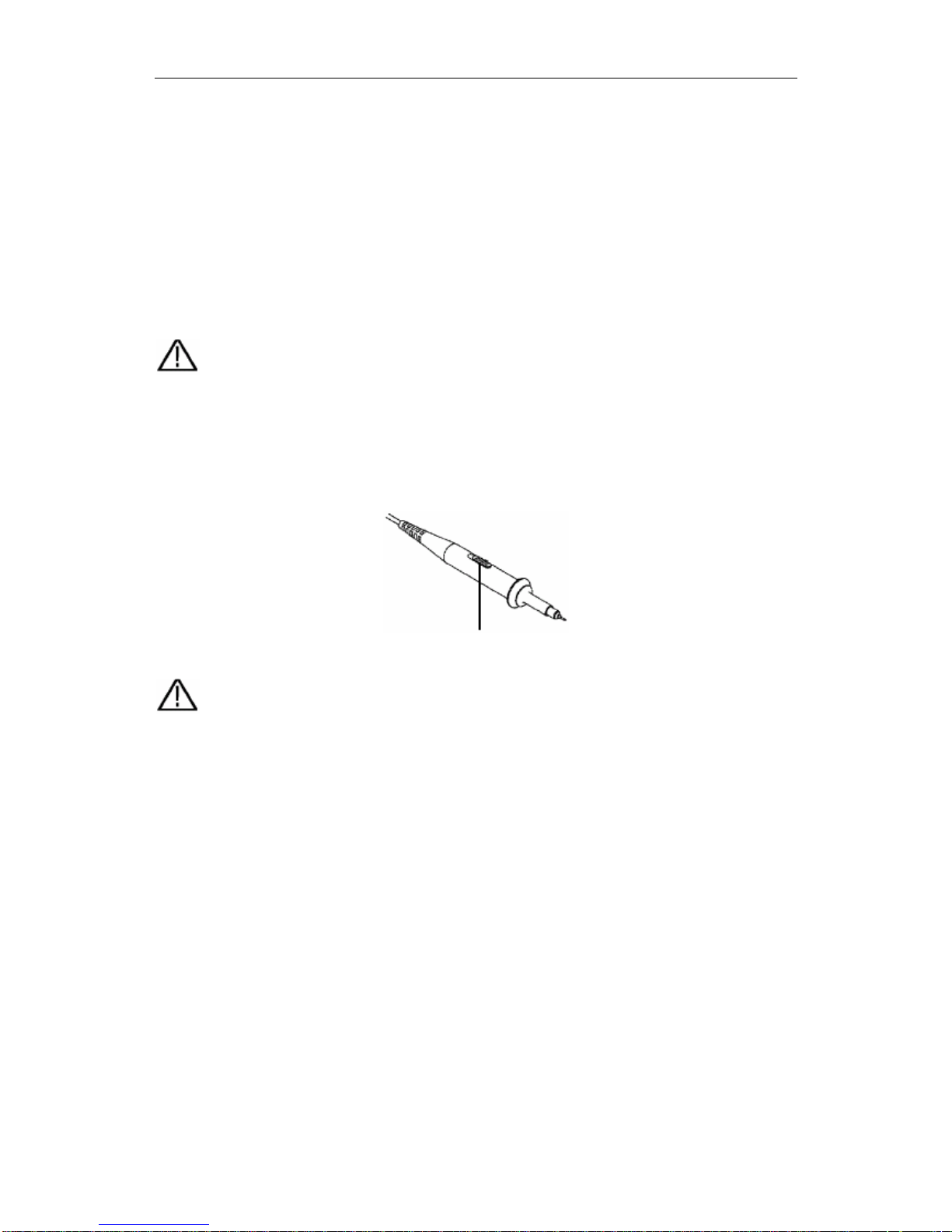
Make sure that the set value of the attenuation switch in the T5100 probe is the same
as the menu selection of the probe in the oscilloscope.
The set values of the probe switch are 1X and 10X (see Fig. 9).
Fig. 9 Attenuation Switch
Note: When the attenuation switch is set to 1X, the T5100 probe will limit the
bandwidth of the oscilloscope in 5MHz. If it is needed to use the whole bandwidth
of the oscilloscope, the switch must be set to 10X.
DS25 Colour Digital Storage Oscilloscope User Manual
20
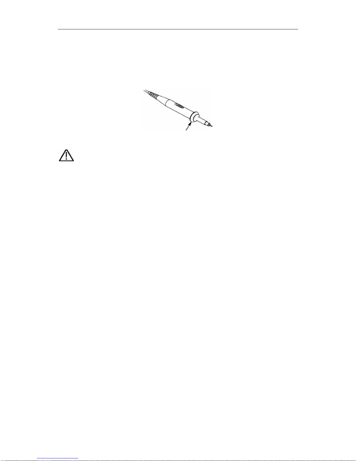
How to Use the Probe Safely
The safety guard ring around the probe body protects your finger against the electric
shock, shown as Fig. 10.
Fig. 10 Finger Guard
Warning: In order to avoid suffering from an electric shock, please keep your
finger behind the safety guard ring of the probe body during operation.
In order to protect you from suffering an electric shock during your use of the
probe, do not touch the metal part of the probe tip when the probe is connected to
the signal source.
Before making any measurements, please connect the probe to the instrument and
connect the ground terminal to the earth.

DS25 Colour Digital Storage Oscilloscope User Manual
21
How to Implement Auto-calibration
The auto-calibration application can make the oscilloscope reach the optimum
condition rapidly to obtain the most accurate measurement value. You can carry out
this application program at any time, but when the range of variation of the ambient
temperature is up to or over 5C, this program must be executed.
For the performing of the self-calibration, all probes or wires should be disconnected
with the input connector first. Then, press the “UTILITY” button to call out the
FUNCTION menu; push down the F3 menu selection button to choose the option
“ Do Self Cal”; finally, run the program after confirming that everything is ready now.
DS25 Colour Digital Storage Oscilloscope User Manual
22
Introduction to the Vertical System
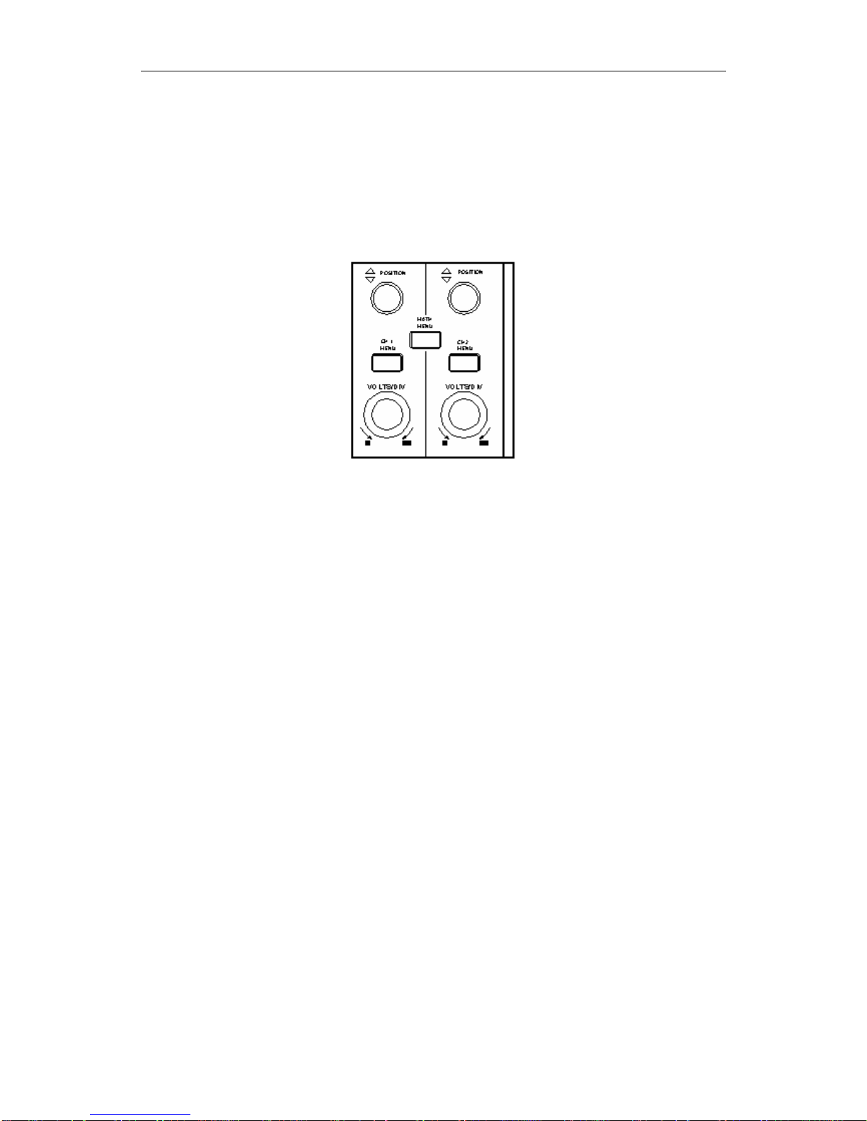
Shown as Fig.11, there are a series of buttons and knobs in VERTICAL
CONTROLS. The following practices will gradually direct you to be familiar with
the use of the vertical setting.
Fig. 11 Vertical Control Zone
1. Use the button “VERTICAL POSITION” knob to show the signal in the center
of the waveform window. The “VERTICAL POSITION” knob functions the
regulating of the vertical display position of the signal. Thus, when the
“VERTICAL POSITION” knob is rotated, the pointer of the earth datum point
of the channel is directed to move up and down following the wave form.
Measuring Skill
If the channel is in the DC coupling mode, you can rapidly measure the DC
component of the signal through the observation of the difference between the wave
form and the signal ground.
If the channel is in the AC mode, the DC component will be removed by filtration.
This mode helps you display the AC component of the signal with a higher
sensitivity.
2. Change the Vertical Setting and Observe the Consequent State Information
Change.
With the information displayed in the status bar at the bottom of the waveform
window, you can determine any changes in the channel vertical scale factor.
Rotate the vertical “VOLTS/DIV” knob and change the “Vertical Scale Factor
(Voltage Division) ”, it can be found that the scale factor of the channel
corresponding to the status bar has been changed accordingly.
Press buttons of “CH1 MENU”, “CH2 MENU” and “MATH MENU”, the
operation menu, symbols, wave forms and scale factor status information of the
corresponding channel will be displayed in the screen.
DS25 Colour Digital Storage Oscilloscope User Manual
23
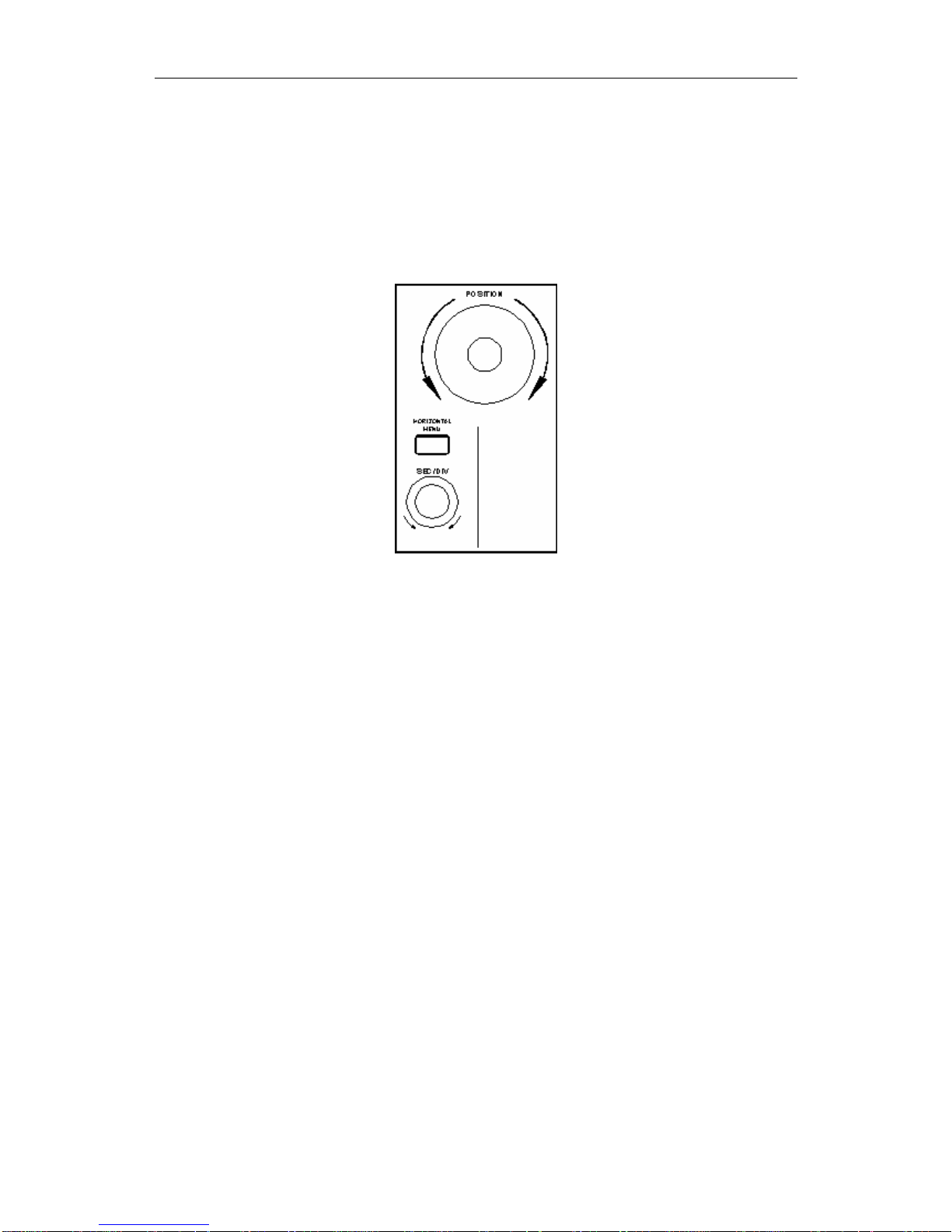
Introduction to the Horizontal System
Shown as Fig.12, there are a button and two knobs in the “HORIZONTAL
CONTROLS”. The following practices will gradually direct you to be familiar with
the setting of the horizontal time base.
Fig. 12 Horizontal Control Zone
1. Use the horizontal “SEC/DIV” knob to change the horizontal time base setting
and observe the consequent status information change. Rotate the horizontal
“SEC/DIV” knob to change the horizontal time base, and it can be found that the
“Horizontal Time Base” display in the status bar changes accordingly. The
horizontal scanning speed steps from 5ns up to 5s in the sequence of 1=2=5.
2. Use the “HORIZONTAL POSITION” knob to adjust the horizontal position of
the signal in the waveform window. The “HORIZONTAL POSITION” knob is
used to control the triggering displacement of the signal or for other special
applications. If it is applied to triggering the displacement, it can be observed that
the wave form moves horizontally with the knob when you rotate the
“Horizontal Position” knob.
3. With the “HORIZONTAL MENU” button pushed down, you can set and
initiate the Window Expansion.

DS25 Colour Digital Storage Oscilloscope User Manual
24
Introduction to the Trigger System
Shown as Fig.13, there are a knob and four buttons in the “TRIGGER
CONTROLS”. The following practices will direct you to be familiar with the setting
of the trigger system gradually.
Fig. 13 Trigger Control Zone
1. Press the “TRIG MENU” button and call out the trigger menu. With the
operations of the 5 menu selection buttons, the trigger setting can be changed.
2. Use the “LEVEL” knob to change the trigger level setting.
With the rotation of the “LEVEL” knob, it can found that the trigger indicator in
the screen will move up and down with the rotation of the knob. With the
movement of the trigger indicator, it can be observed that the trigger level value
displayed in the screen changes.
3. Press the button “SET TO% 50” to set the trigger level as the vertical mid point
values of the amplitude of the trigger signal.
4. Press the “FORCE TRIG” button to force a trigger signal, which is mainly
applied to the “Normal" and "Single” trigger modes.
5. The “TRIG VIEW” button is used to reset the trigger horizontal position.
 Loading...