

Page 1

QUICK REFERENCE GUIDE
ENGLISH VERSION 1.02
The Benchmark for Value in CCTV
VCE400 SERIES
P e n t a p l e x N e t w o r k D V R
© Copyright 2007 Digimerge Technologies Inc.
Page 2

www.digimerge.com
VCE400 Series QSG_EN_R1 Page 2
Information in this do cument is subject to ch ange without notice. A s our products are sub ject to continuous imp rovement, Digimerge Te chnologies Inc. reserve s the right to modify product design, specifi cations and prices, wi thout notice and witho ut incurring any obliga tion. E&OE © 2007 Digi merge. All rights rese rved.
STEP 1
SETTING UP YOUR DIGTIAL VIDEO RECORDER (DVR)
*
This set-up guide assumes you are connecting cameras (not included) to the Digimerge DVR. Consult
your DVR’s owners manual for alternative DVR connection and/or information to install a hard drive.
1
Connect the cameras (not supplied) to the CH1,
CH2, CH3, CH4 Video Inputs (BNC Inputs)
2
Insert the power cord to the DVR
Your system is now ready to use. Refer to your DVR’s
owner’s manual to learn how to record, playback, use
the search features and all other features available
with this system. Refer to Dynamic DNS Setup (Step
4) for Setting Up Remote Security Monitoring.
NOT INCLUDED - CAMERAS / BROADBAND ROUTER
BACK OF THE DVR
PA CK AGE C ONT EN TS
BACK OF THE DVR
FRONT OF THE DVR
1 - VCE400 Series Digital Video Recorder
1 - Owners Manual & Warranty
1 - Remote controller
1 - Need Help Insert
1 - Power Cord
2 - Power Batteries (AAA Size)
2 - Rack Mount
1 - Quick Installation Guide
1 - VCE400/300 Series DVR software and Support Disk
4
Ensure to turn ON the Power switch (located on the
front of the DVR)
POWER CORD
3
Insert the other end of the Power Cord to an electrical outlet
BACK OF THE DVR
Page 3
www.digimerge.com
VCE400 Series QSG_EN_R1 Page 3
Information in this do cument is subject to ch ange without notice. A s our products are sub ject to continuous imp rovement, Digimerge Te chnologies Inc. reserve s the right to modify product design, specifi cations and prices, wi thout notice and witho ut incurring any obliga tion. E&OE © 2007 Digi merge. All rights rese rved.
STEP 2
SETTING UP YOUR DIGTIAL VIDEO RECORDER (DVR) - BASIC - NETWORK SETUP
2
3
1
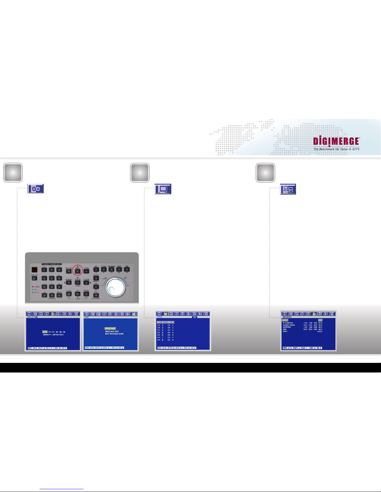
Setting Date & Time
Press the “Menu” Button
Use the Left or Right Arrows to Navigate to the
“System” Menu
Move down to “Clock” and press “status/home/enter”
Select “Date&Time” and press “status/home/enter”
Use the arrow keys to highlight which entry to modify
(year/month/day hour:minute:second)
Use the “F-” (auto) or “F+” (freeze) keys to decrement
or increment the highlighted values
Press “status/home/enter” to set the time
Press the “Spot/ESC” button 3 times
Move to “Save and Exit” and press “status/home/enter”
Setting Camera Names
Press the “Menu” Button
Use the Left or Right Arrows to Navigate to the
“Screen” Menu
Move down to “Title” and press “status/home/enter”
Select desired channel number (i.e. CH 1:) and press
“status/home/enter
Use the directional arrows to Highlight the desired
letters or numbers, Press the
“status/home/enter” to
select the letter
Repeat this process until the camera name is displayed
in the
“CH x: ” section
To make corrections to the data entered, you can
use the “F-” (auto) or “F+” (freeze) keys to highlight
the letter in the “CH x:” section you want to change/
modify, then use the directional arrows to highlight the
letter you want to change it to, press the “status/home/
enter” to change the selected character
Press “Spot/ESC” to set the Camera Name
Repeat this process for each Channel
Press the “Spot/ESC” button 2 times
Move to “Save and Exit” and press “status/home/enter”
Network Setup
Press the “Menu” Button
Use the Left or Right Arrows to Navigate to the “Link”
Menu
Select “Network” and press “status/home/enter”
For more information on these features, refer to the
VCE400 Series Manual, under the “6.6.1 Network”
section
Press the “Spot/ESC” button 2 times
Move to “Save and Exit” and press “status/home/enter”
MENU
Page 4
www.digimerge.com
VCE400 Series QSG_EN_R1 Page 4
Information in this do cument is subject to ch ange without notice. A s our products are sub ject to continuous imp rovement, Digimerge Te chnologies Inc. reserve s the right to modify product design, specifi cations and prices, wi thout notice and witho ut incurring any obliga tion. E&OE © 2007 Digi merge. All rights rese rved.
STEP 2
SETTING UP YOUR DIGTIAL VIDEO RECORDER (DVR) - DYNAMIC DNS & MOTION DETECTION SETUP
5a
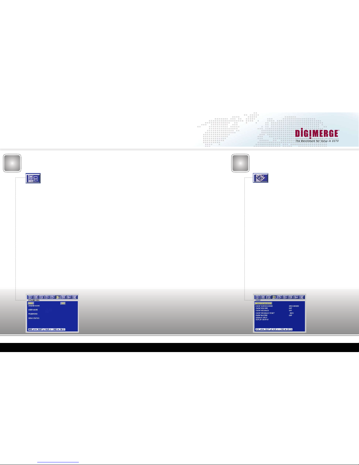
Motion Detection Setup
4
Dynamic DNS Setup
CHECK STEP 4 FOR DETAILED
INFORMATION
Press the “Menu” Button
Use the Left or Right Arrows to Navigate to the “Event” Menu
Move down to “Event Record”, Use the “F-” (auto) or “F+”
(freeze)
keys to set the value to “On”
This setting will enable the event recording, ie: Internal Pixel
based motion detection or external dry contacts; by default,
this setting is “Off”
Move down to “Event Message”, Use the “F-” (auto) or “F+”
(freeze)
keys to set the value to “On”
When this setting is enabled, the OSD will display “MOTION”
over the Channel Number, when Motion is detected; by default
this setting is “Off”
Press “Spot/ESC”
Move to “Save and Exit” and press “status/home/enter”
For the VCE400 to record on Motion (detection) Events, you
will need to follow the Motion Detection Area Setup, and the
Custom Program setup
The information provided in the ‘DDNS Conrmation Email’ needs to
be on hand when completing this section
Press the “Menu” Button
Use the Left or Right Arrows to Navigate to the “Link” Menu
Move down to “Dynamic DNS” and press “status/home/enter”
Use the “F-” (auto) or “F+” (freeze) keys to toggle the “DDNS” value
to
“On”
Move down to “Domain Name” and press “status/home/enter”
Use the directional arrows to Highlight the desired letters or numbers,
Press the
“status/home/enter” to select the letter
Repeat this process until the full domain name is displayed in the “Do
main Name”
section
To make corrections to the data entered, you can use the “F-“
(auto) or “F+” (freeze) keys to high light the letter in the “Do
main Name” section you want to change/modify, then use the
directional arrows to highlight the letter you want to change it
to, press the “status/home/enter” to change the selected character
Press “Spot/ESC” to set the domain name
Move down to “User Name” and press “status/home/enter”
Use the directional arrows to Highlight the desired letters or numbers,
Press the
“status/home/enter” to select the letter
Repeat this process until the full user name is displayed in the “User
Name”
section
To make corrections to the data entered, you can use
the “F-“ (auto) or “F+” (freeze) keys to highlight the
letter in the “User Name” section you want to change/
modify, then use the directional arrows to highlight the
letter you want to change it to, press the “status/home/
enter” to change the selected character
Press “Spot/ESC” to set the user name
Move down to “Password” and press “status/home/enter”
Use the directional arrows to Highlight the desired letters
or numbers, Press the
“status/home/enter” to select the
letter
Repeat this process until the full Password has been en tered, the
“Password” section in this menu will not display
the password as it is entered; this is for security purposes
To make corrections to the data entered, you can use
the “F-“ (auto) or “F+” (freeze) keys to highlight the let ter in the “Password” section you want to change/modify,
then use the directional arrows to highlight the letter you
want to change it to, press the “status/home/enter” to
change the selected character
Press “Spot/ESC” to set the password
Press “Spot/ESC” 2 more times
Move to “Save and Exit” and press “status/home/enter”
Page 5

www.digimerge.com
VCE400 Series QSG_EN_R1 Page 5
Information in this do cument is subject to ch ange without notice. A s our products are sub ject to continuous imp rovement, Digimerge Te chnologies Inc. reserve s the right to modify product design, specifi cations and prices, wi thout notice and witho ut incurring any obliga tion. E&OE © 2007 Digi merge. All rights rese rved.
5b
STEP 2
SETTING UP YOUR DIGTIAL VIDEO RECORDER (DVR) - MOTION DETECTION, RECORD PROGRAM SETUP
Press the “Menu” Button
Use the Left or Right Arrows to Navigate to the “Event” Menu
Select “Motion Detection” and press “status/home/enter”
In this menu, you can modify the Sensitivity for each cam-
era, along with the motion detection area; “dead zones” can be
congured in areas where there will be constant or unwanted
motion
Channel: This will display which channel number you are modi-
fying, Use the
“F-” (auto) or “F+” (freeze) keys to decrement
or increment the Channel value
Sensitivity: This will show the current sensitivity for the for
the selected channel;
“1” is the lowest, “5” is the highest; by
default this value is
“3”, Use the “F-” (auto) or “F+” (freeze)
keys to decrement or increment the sensitivity value
Area Setup: This menu will allow you to congure your ‘dead
zones’ or areas in which you do not want the VCE400 to de-
tect motion; Press the
“status/home/enter”, and use the
arrow keys to highlight which square you wish to block
out. Press the
“status/home/enter” key. This will remove the
green tint from the selected square. The VCE400 will ignore
motion in all of the non-green squares. By default, all
the detection areas are turned “On” (green).
Press “Spot/ESC” to set the motion area
Press “Spot/ESC” 2 more times
Move to “Save and Exit” and press “status/home/enter”
Motion Detection
Area Setup
6
Record Program
Setup
Use the “F-” (auto) or “F+” (freeze) keys to decrement or in
crement the Resolution value; the options are (320x240,
720x240, 720x480)
Setting Normal (continuous) Record IPS
The Normal IPS Settings are only used when the “Record”
button is pressed.
Please refer to Chart#1 for Maximum record IPS (images per
second) per channel for each resolution
The maximum IPS value per channel is 30 ips
Move down to highlight the values located below the “Normal
IPS” Column
Use the “F-” (auto) or “F+” (freeze) keys to decrement or incre ment the highlighted Normal IPS values
Repeat this process for each Channel
The Sum of these IPS values cannot exceed the Maximum IPS
for the desired resolution
Note: if you are planning on connecting to the DVR over the
network, do not set the “Normal IPS” to a value lower then 1
IPS per channel, as the “live” video will not be transmitted over
the network
CHANNEL
SENSITIVITY
AREA SETUP
TEST MOTION
Chart #1
Recording Program Setup (Custom Program Setup)
Press the “Menu” Button
Use the Left or Right Arrows to Navigate to the “Record” Menu
Move down to “Record Program” and press “status/home/enter”
The Record Program menu denes how you want the DVR to
record, this includes Resolution, Normal IPS, Event
IPS, Quality, Pre-Alarm, and Post Alarm Settings.
Use the arrow keys to highlight which entry to modify
At the top of the screen, make sure that “Rec Program” is set to
“Program0” Use the “F-” (auto) or “F+” (freeze) keys to switch
Program Numbers
At the top of the screen, make sure that “Event Rec Type” is
set to “Complex/Event CH Only”, Use the “F-” (auto) or “F+”
(freeze) keys to switch Record Program Type
Setting the Recording Resolution
Please refer to Chart#1 for Maximum record IPS (images per
second) per channel for each resolution
Move down to highlight the value located below the “Image
Size” Column
VCE400 Resolution
VCE416
Total IPS
VCE416 Max
IPS / Channel
VCE408
Total IPS
VCE408 Max
IPS / Channel
VCE404
Total IPS
VCE404 Max
IPS / Channel
360x240 480 30 240 30 120 30
720x240 240 15 120 15 120 30
720x480 120 7.5 60 7.5 120 30
Page 6

www.digimerge.com
VCE400 Series QSG_EN_R1 Page 6
Information in this do cument is subject to ch ange without notice. A s our products are sub ject to continuous imp rovement, Digimerge Te chnologies Inc. reserve s the right to modify product design, specifi cations and prices, wi thout notice and witho ut incurring any obliga tion. E&OE © 2007 Digi merge. All rights rese rved.
STEP 2
SETTING UP YOUR DIGTIAL VIDEO RECORDER (DVR) - RECORD PROGRAM (continued)
6
Record Program
Setup (Continued)
Setting Event (alarm/motion detection) Record IPS
The Event IPS Settings are only used with an Event is trig-
gered, for example an internally detected motion event, or an
external alarm contact
Please refer to Chart#1 for Maximum record IPS (images per
second) per channel for each resolution
Move right to highlight the values located below the “Event IPS”
Column
Use the “F-” (auto) or “F+” (freeze) keys to decrement or incre ment the highlighted Event IPS values
Repeat this process for each Channel
The Sum of these IPS values cannot exceed the Maximum IPS
for the desired resolution
For the VCE400 to record on Motion (detection) Events, you
will need to enable the Event Record, in the Event Menu (Refer
to the Motion Detection Setup Section 5a)
Setting Continuous/Event Record Quality
Quality N Settings are used during continuous/normal recordings
Quality E Settings are used only when Event recording is trig-
gered, such as internally detected motion, or an external alarm
contact
Setting Event Recording (A/L/M) Triggers
These settings dictate what type of events will trigger the
VCE400 to record; by default these are all enabled
“O” indicates the option is enabled, “-“ indicates the option is
disabled
“A” indicates an externally triggered alarm contact (dry contact,
such as a door trigger, or motion sensor)
“L” indicates the pre-alarm buffer will be recorded in the event
of a Video Loss
“M” indicates an internal pixel based motion detection trigger
(standard motion detection)
Move right to highlight the value located below the “Event A/L/
M” Column
Use the “F-” (auto) or “F+” (freeze) keys to modify the high-
lighted Event A/L/M values
Repeat this process for each Channel
For more information on these features, refer to the VCE400
Series Manual, under the “6.4.7 Sensor Input” section
Press “Spot/ESC” 2 times
Move down to “Save and Exit” and press “status/home/enter”
Move right to highlight the values located below the “Quality
N/E” Column
Use the “F-” (auto) or “F+” (freeze) keys to modify the high
lighted Record Quality values
“B” Indicates Best Quality recording
“H” Indicates High Quality recording
“N” Indicates Normal Quality recording
Repeat this process for each Channel
Setting Pre-Alarm and Post Alarm Record Times
The Pre-Alarm time reects the amount of video that is re-
corded before an Event is triggered (Maximum setting is
5 seconds; this setting is global for all the cameras)
The Post-Alarm time is the duration of the recording after the
event has stopped triggering (Maximum setting is 60 seconds;
this setting is camera independent)
Move right to highlight values located below the “Pre/Post Time”
Column
Use the “F-” (auto) or “F+” (freeze) keys to decrement or incre ment the highlighted Pre/Post Time values
Repeat this process for each Channel
Page 7

www.digimerge.com
VCE400 Series QSG_EN_R1 Page 7
Information in this do cument is subject to ch ange without notice. A s our products are sub ject to continuous imp rovement, Digimerge Te chnologies Inc. reserve s the right to modify product design, specifi cations and prices, wi thout notice and witho ut incurring any obliga tion. E&OE © 2007 Digi merge. All rights rese rved.
STEP 2
SETTING UP YOUR DIGTIAL VIDEO RECORDER (DVR) - RECORD SCHEDULE SETUP, ENABLING THE PASSWORD
7
8
Setting the Record
Schedule
Scheduled Continuous Recording
The DVR can be congured to schedule the Continuous/Nor-
mal recording. For example, if you want the VCE400 to
record continously from 8.00am to 6.00pm, and then record
only on motion after those hours, use the arrow keys to
highlight which time period you want to enable the
Scheduled Continuous Recording for (i.e. starting
at 8.00 hours). Turn the jog dial to the right (clockwise) to
enable the Continuous Schedule Recording, or turn the jog
dial to the left (counter-clockwise) to disable the Continuous
Schedule Recording for the selected hour
When Scheduled Continuous Recording is enabled the selected
hour(s) will be highlighted in green. When Scheduled Continu ous Recording is disabled, the program number will be white
This Scheduled Continuous Recording Feature Requires Firm ware/Software V2.65 or later
Repeat this process for each day/hour
For more information on these features, refer to the VCE400
Series Manual, under the “6.3.1 Record Setup” section
Press “Spot/ESC” 2 times
Move down to “Save and Exit” and press “status/home/enter”
In this menu, you can congure a weekly recording schedule;
this schedule can include any of the pre-dened or custom
programs. You can select different custom programs for
different periods of time, for example you can set the
VCE400 to record continuously from 8am to 6pm
(regular business hours), and then record only on
motion after-hours
Press the “Menu” Button
Use the Left or Right Arrows to Navigate to the “Record” Menu
Select “Record Setup” and press “status/home/enter”
This menu is segmented into 1 hour durations; you can indi-
vidually select different programs per hour, per day. If you
have setup a Custom program as outlined in the previous
steps, change all the numbers in the schedule to “0”
Use the arrow keys to highlight which time period you want to
modify; or highlight the
“All” column for that day to change all
the values.
Use the “F-” (auto) or “F+” (freeze) keys to decrement or in
crement the highlighted Schedule values
Enabling these setting will cause the VCE400 to prompt
the user for a password whenever they attempt to enter the
menu, or change the record status; the default admin
password is “11111111”
Press the “Menu” Button
Use the Left or Right Arrows to Navigate to the “System”
Menu
Move down to “Advanced Setup” and press “status/home/
enter”
Select “Password Check”; Use the “F-” (auto) or “F+” (freeze)
keys to change the value to “On”
Press “Spot/ESC” 2 times
Move down to “Save and Exit” and press “status/home/enter”
Enabling the
VCE400 Password
Page 8

www.digimerge.com
VCE400 Series QSG_EN_R1 Page 8
Information in this do cument is subject to ch ange without notice. A s our products are sub ject to continuous imp rovement, Digimerge Te chnologies Inc. reserve s the right to modify product design, specifi cations and prices, wi thout notice and witho ut incurring any obliga tion. E&OE © 2007 Digi merge. All rights rese rved.
STEP 2
SETTING UP YOUR DIGTIAL VIDEO RECORDER (DVR) - SETTING & RESETTING THE PASSWORD,
FORMATTING THE HARD DRIVE AND
RESETTING TO FACTORY DEFAULTS
It is recommended that the Admin Password be reset after
installation, for security purposes
Press the “Menu” Button
Use the Left or Right Arrows to Navigate to the “System” Menu
Move down to “Advanced Setup” and press “status/home/enter”
Move down to “Set Password” and press “status/home/enter”
Select “Admin Password” and press “status/home/enter”
Use the number buttons on the front of the DVR to enter in your
new numeric password, this password can be up to 8 characters
long. You will have to re-type the password for verication
purposes.
The DVR will return “Password Changed Successfully” if the
‘New Password’ and the ‘Re-type’ elds are the same
Press “Spot/ESC” 2 times
Move down to “Save and Exit” and press “status/home/enter”
Setting & Resetting
VCE400 Admin Password
This option will return the unit to an out-of-box condition;
all settings will be erased, and reset to their factory settings
Press the “Menu” Button
Use the Left or Right Arrows to Navigate to the “System”
Menu
Move down to “Advanced Setup” and press “status/home/
enter”
Move down to “DVR Menu Setup” and press “status/home/
enter”
Select “Factory Default” and press “status/home/enter”
Move down to highlight “Yes” and press “status/home/
enter”
The VCE400 will not be ‘defaulted’ until you “Save and
Exit”
Press “Spot/ESC” 3 times
Move down to “Save and Exit” and press “status/home/
enter”
9
Warning: Proceeding with these steps will result
in a loss of all recorded data on the VCE400
Press the “Menu” Button
Use the Left or Right Arrows to Navigate to the
“System” Menu
Select “HDD” and press “status/home/enter”
Move down to “Rec HDD Format” and press “status/
home/ enter”
Warning: Selecting “Yes” to this option will erase all
of your Record Video and Audio
Move down to “Yes” and press “status/home/enter”
Press “Spot/ESC” 2 times
Move down to “Save and Exit” and press “status/
home/enter”
Formatting the VCE400
Hard Drive
10
11
Resetting VCE400 to
Factory Defaults
Page 9

www.digimerge.com
VCE400 Series QSG_EN_R1 Page 9
Information in this do cument is subject to ch ange without notice. A s our products are sub ject to continuous imp rovement, Digimerge Te chnologies Inc. reserve s the right to modify product design, specifi cations and prices, wi thout notice and witho ut incurring any obliga tion. E&OE © 2007 Digi merge. All rights rese rved.
How to do a Time
Search
How to Copy Recorded
Data to a CD-ROM
from VCE400
1
STEP 3
DIGTIAL VIDEO RECORDER (DVR) - BASIC OPERATION - HOW TO DO A TIME SEARCH, EVENT SEARCH,
COPYING RECORDED DATA TO A CD-ROM
Press the “Search” Button
Move down to “Time Search” and press “status/home/enter”
Use the directional arrows to Highlight the desired information
(Year/Month/Day Hour:Minute:Second); Use the “F-” (auto) or
“F+” (freeze) keys to decrement or increment the highlighted
values
Once you have entered desired start time for the search, Press
the
“status/home/enter”
After the recording has started to play you can use the VCR
style controls (Fast Forward, Pause, Slow Motion, Change
Direction)
To return to the live view of the VCE400, press “LV/PB” (Live/
Playback)
This feature will only work if you have the VCE400
setup for Event Recording (see previous sections on
Event Recording)
Press the “Search” Button
Move down to “Event Search” and press “status/
home/enter”
Select “HDD ID: REC” and press “status/home/enter”
Use the directional arrows to Highlight the desired
Event, Press the
“status/home/enter”
After the recording has started to play you can use
the VCR style controls (Fast Forward, Pause, Slow
Motion, and Change Direction)
This will play the recorded video until the selected
event stopped recording; the VCE400 will return
“Completed” at the end of the recording
To return to the live view of the VCE400, press “LV/
PB”
(Live/Playback)
How to do an Event
Search
SEARCH / COPY
For best results use only CD-R, or pre-formatted CD-RW
media
Press the “Copy” Button
Select “Copy” and press “status/home/enter”
Select “Media: USB_FRONT”; Use the “F-” (auto) or “F+”
(freeze)
keys to change the value to “Media: INTERNAL CD-
RW/DVD”
By default, all channels are set to be recorded to the CD-R
“O” indicates that the Channel will be recorded to the CD-R
“-“ indicates that the Channel will not be recorded to the CD- R
If you do not want to copy all the Channels to the CD-R, Move
down to
“Channel”, Use the directional arrows to Highlight the
channel indicators. Use the
“F-” (auto) or “F+” (freeze) keys to
modify the highlighted values
Move down to “Copy Start Time” Use the directional arrows to
Highlight the desired information (Year/Month/Day Hour:Minute:
Second); Use the
“F-” (auto) or “F+” (freeze) keys to decrement
or increment the highlighted values
Move down to “Copy End Time” Use the directional arrows to
Highlight the desired information (Year/Month/Day Hour:Minute:
Second); Use the
“F-” (auto) or “F+” (freeze) keys to decrement
or increment the highlighted values
Press “status/home/enter”, to nalize the copying settings
At the “Password Input” Screen, Use the number buttons on
the front of the DVR to enter in your numeric password, this pass
word can be up to 8 characters long; If you do not want to pass
word protect the video you are copying to CD-R, Press
“Spot/ESC”
This should return you back to the main camera screen; the
“Copying Status” should be displayed in the upper right hand
corner of the screen
2
3
Page 10

www.digimerge.com
VCE400 Series QSG_EN_R1 Page 10
Information in this do cument is subject to ch ange without notice. A s our products are sub ject to continuous imp rovement, Digimerge Te chnologies Inc. reserve s the right to modify product design, specifi cations and prices, wi thout notice and witho ut incurring any obliga tion. E&OE © 2007 Digi merge. All rights rese rved.
STEP 4
DYNAMIC DNS SETUP FOR REMOTE SECURITY MONITORING
Connect one end of ethernet cable (not supplied) to the DVR, the other end to the broadband router (not included). Power router and
DVR ON if not already ON
Port forwarding Your Router and the Creation of a DDNS Account with Digimerge is required in order for you to have Remote Internet Access.
Record the MAC Address
Open your Web Browser. Enter
http://ddns.digimerge.net
http://ddns.digimerge.net
To find the DVR’s MAC address , press the
STATUS button on your DVR; t he MAC address
can be found on page 2/2 of the DVR Status
Screen.
STATUS
1
2
3
WAN (WIDE AREA
NETWORK)
LAN (LOCAL AREA NETWORK)
BACK OF A GENERIC DVR
BACK OF A ROUTER (NOT INCLUDED)
TO YOUR COMPUTER
Page 11

www.digimerge.com
VCE400 Series QSG_EN_R1 Page 11
Information in this do cument is subject to ch ange without notice. A s our products are sub ject to continuous imp rovement, Digimerge Te chnologies Inc. reserve s the right to modify product design, specifi cations and prices, wi thout notice and witho ut incurring any obliga tion. E&OE © 2007 Digi merge. All rights rese rved.
8
7
5
6
4
STEP 4
DYNAMIC DNS SETUP FOR REMOTE SECURITY MONITORING (continued)
Port forwarding Your Router and the Creation of a DDNS Account with Digimerge is required in order for you to have Remote Internet Access.
Select the Create New Account Link
Complete Account Information
1. For Product License: Select
your Product Model Number
from the drop down menu
(VCE400 Series)
2. For Product Code enter the
MAC address (without any
space) recorded earlier
3. For URL Request choose a
URL Name (not to exceed 15
characters) (e.g. your name,
your company etc.)
1 2
3
Select the Create Account Option
Create Account
An Automated Confirmation email will be sent
to you. Record the information below
Port Forward your Router. You will need to
Forward port 5400 (default).
All routers are different. To Port Forward your
Router:
Refer to your Router’s manual for specific instructions on port forwarding
DDNS: ON
Domain name: johndenver
User name: johndenver1
Password: <enter the password>
DDNS Status: GOOD
The DDNS Status will show GOOD if your configuration is OK.
Once the DDNS Account has been configured (and the account
details are received in Email), then these settings can be added to the
DVR unit. See the DDNS Set menu options on your owner’s manual
for further details.
Once you finish entering the information press ESC twice and use
the option SAVE ONLY.Go back to the menu LINK /DYNAMIC DNS
and check the DDNS status.
VCE400 Series
Note : If your status is FAILED, check your settings or your internet
connection and try again.
Page 12

www.digimerge.com
VCE400 Series QSG_EN_R1 Page 12
Information in this do cument is subject to ch ange without notice. A s our products are sub ject to continuous imp rovement, Digimerge Te chnologies Inc. reserve s the right to modify product design, specifi cations and prices, wi thout notice and witho ut incurring any obliga tion. E&OE © 2007 Digi merge. All rights rese rved.
9
STEP 4
DYNAMIC DNS SETUP FOR REMOTE SECURITY MONITORING (continued)
Accessing the DVR Locally / Remotely with a PC
Port forwarding Your Router and the Creation of a DDNS Account with Digimerge is required in order for you to have Remote Internet Access.
Once the DVR and the Local Network have been successfully configured,
a connection can be made with a Local PC (a PC within the same network
as the DVR), or remotely (a PC from outside the network via the Internet).
The DVR List should appear, fill in the appropriate network and
password information and click the “Add” Button.
NOTE: YOUR COMPUTER AND YOUR DVR MUST BE
CONNECTED TO THE SAME ROUTER
The DVR information should be populated in the above list,
Select the DVR by clicking on it, and then click on the Connect
Button. A login window should appear, Enter in the DVR’s 8
digit password, and press “Ok”.
Logging Into Live Monitoring
Once the DigiClient has been installed and has been launched on the computer,
a pop-up window will appear. It should ask you to Register an Admin Password
(this password is separate from the numeric DVR password, this password will
only be used to login to the DigiClient Software).
Login in as “Administrator”, and enter DigiClient Administrator password .
The DigiClient software interface will load once you have successfully logged in.
Click on the “DVR List” button located in the top left of the DigiClient 4.0 Screen.
10
If the DVR and the software are correctly configured, the
cameras should display in the DigiClient Screen.
For addi tiona l in forma tion or t roub lesh ootin g he lp, r efer to y our owne rs ma nual
for assi stanc e. Y ou ca n al so ca ll o r em ail f or f urthe r su pport .
To ll Fr ee T ec hni ca l Su pp ort : 1- 86 6- 344 -4 67 4 or +9 05 -9 46 -84 77
Em ai l S up po rt : t ec h@ di gi mer ge .c om
We bs ite : ww w. dig im er ge .c om
It’s all on the web
Product Information
User Manuals
Quick Start Guides
Specification Sheets
Software Updates
Firmware Upgrades
 Loading...