

Page 1
V
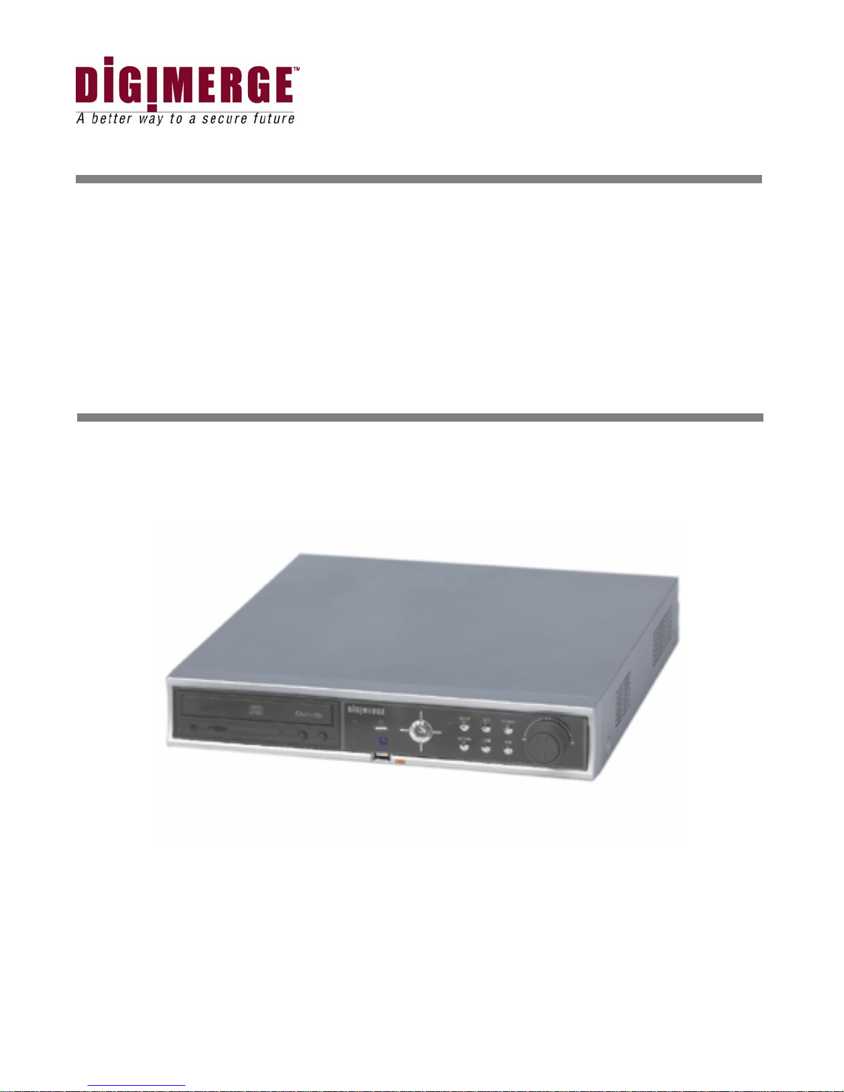
CD 300 Series
4/8/16 Channel Network DVR
Models: VCD304161, VCD308161, VCD316161
Installation / User Manual
Digimerge Technologies Inc.
V.103105
Page 2

WARNING
TO REDUCE FIRE OR SHOCK HAZARD, DO NOT EXPOSE
THE UNIT TO RAIN OR MOISTURE.
This installation should be made by a qualified service person and should
conform to all local codes.
Page 3

Cautions
Read Before System Operation
Follow these details to prevent material damage or personal injury.
Signs of Caution and Warning
Warning: This sign indicates that the user could die or be seriously wounded if not used or
installed properly.
Caution: This sign indicates that the user could be wounded or could expect property damage
if not used or installed properly.
Warning: Do not expose the product to fog, rain or too much humid to decrease danger from
electric shock or fire.
Important Safeguards
Warning
1. Change the battery after turning the off the power of the product.
2. Check the polarity of the lithium battery while changing.
3. Change the battery with the same one, which is in the product or with the similar type recommended by your vendor.
4. Dispose of the changed battery according to the instructions of the battery manufacturer.
※ There is danger of explosion when instructions are not followed.
General Warning
Warning
1. Use the power cord, which is supplied or recommended by the supplier.
It may cause fire.
2. Do not dismantle or assemble the product.
It may cause malfunction or fire.
3. Enquire from your vendor for repair.
It may cause electric shock or fire if the repair is not done properly.
4. Do not touch the product with wet hands.
It may cause malfunction or electric shock.
5. Matters must be ensured to a professional for product installation.
It may cause malfunction, electric shock or fire.
6. Consult the place of purchase if the need for installation arises.
Delinquent installation may be the reason for malfunction, electric shock or fire.
7. Ground applies to video products equipped with a 3-wire grounding type plug having a third (grounding) pin.
This plug only fits into a grounding-type power outlet.
If grounding is not done, it may cause malfunction or electric shock.
8. Ground connection must not touch gas pipe, water pipe or telephone line.
If grounding is not done properly, it may cause electric shock.
9. Prevent metallic foreign substance from going inside the product.
It may cause malfunction or electric shock.
10. Do not spray insecticide or flammable spray while driving.
It may cause fire.
11. Prevent water from entering inside electrical parts.
Clean with a dry towel or malfunction or electric shock could result.
Page 4

Page 5

Caution
1. Use the power cord, which is supplied or recommended by the supplier.
The internal fan rotates at high speed and may cause an accident.
2. Do not drop, give strong vibration, or shock to the product.
It may cause malfunction.
3. The air inhaler of the front panel and air outlet of the back panel must not be blocked during installation.
The internal temperature of the product would be greater than allowable and could cause malfunction or
fire.
4. Do not touch the product or the power cord when there is thunder.
It may cause electric shock.
5. Do not install the product near or on top of heating source.
The internal temperature of the product would be greater than allowable and could cause malfunction or
fire.
6. Do not install the product on inclined or unstable location or where vibration could be committed.
It may cause malfunction.
Cautions about the Power
Warning
1. Must use the outlet of the grounding to connect the power cord.
It may cause fire.
2. Do not connect on the middle of power cord or use extension cord.
It may generate heat or cause fire.
3. Do not touch the power cord with wet hands.
It may cause electric shock.
4. Keep power cord dry and protect from humidity.
It may generate heat or cause fire. The power cord is not waterproof.
5. Hold the body of the plug while removing the power plug.
Do not pull the power cord. Damage to the power cord may generate heat or cause fire.
6. Check the power plug regularly.
Humidity and moderation in smoking may cause fire.
7. Remove power cord from outlet when product is not used for a long time.
It may cause short-circuit or electric shock.
Caution
1. Do not turn off the power by removal of the power plug.
To turn off the power, click the power button from the front panel.
When the system stops abnormally, the power button might not work. Click power button for 5 full seconds to turn
power off.
2. Do not cut off the power artificially, or give shock or vibration to unit while the hard disk is activating.
It may cause hard disk failure or loss of data.
Page 6

Category
1.
SYSTEM STRUCTURE AND INSTALLATION................................................................................................. 0
2. EXPLANATIONS FOR EACH FUNCTION........................................................................................................ 1
2.1 FRONT PANEL ............................................................................................................................................................................... 1
2.2 IR REMOTE CONTROLLER ............................................................................................................................................................ 4
2.3 REAR PANEL ................................................................................................................................................................................. 6
2.4 PTZ CONNECTIONS ................................................................................................................................................................. 8
3. INSTALLATION..................................................................................................................................................... 10
3.1 CONNECTING PERIPHERAL DEVICES.......................................................................................................................................... 10
3.2 SYSTEM STARTUP AND SHUTDOWN ............................................................................................................................................11
4. OPERATION .......................................................................................................................................................... 14
4.1 LOG IN ........................................................................................................................................................................................ 14
4.2 REAL TIME LIVE MODE .............................................................................................................................................................. 15
4.3 RECORDING IMAGE PLAYBACK MODE ...................................................................................................................................... 17
4.4 SEARCH RECORDING IMAGE ...................................................................................................................................................... 18
5. SETTING ................................................................................................................................................................ 21
5.1 RECORDER - GENERAL ............................................................................................................................................................... 23
5.2 RECORDER-TIME & DAT E .......................................................................................................................................................... 27
5.3 RECORDER-BACKUP................................................................................................................................................................... 29
5.4 RECORDER-DISK FORMAT.......................................................................................................................................................... 33
5.5 DELETING HARD DRIVE DATA AND SETUP CONFIGURATION....................................................................................................... 34
5.6 RECORDER-PASSWORDS............................................................................................................................................................. 35
5.7 RECORDER-LOG OFF .................................................................................................................................................................. 40
5.8 CAMERA-COMMON .................................................................................................................................................................... 41
5.9 CAMERA-RECORDING ................................................................................................................................................................ 44
5.10 CAMERA-SCHEDULE .................................................................................................................................................................. 48
5.11 CAMERA-COLOR ........................................................................................................................................................................ 50
5.12 CAMERA- PTZ............................................................................................................................................................................ 52
5.13 CAMERA- AUDIO ........................................................................................................................................................................ 53
5.14 ALARM IN/OUT .......................................................................................................................................................................... 54
5.15 ALARM-MOTION ALARM ........................................................................................................................................................... 56
5.16 ALARM-VIDEO LOSS .................................................................................................................................................................. 57
5.17 ALARM-SMART ALARM ............................................................................................................................................................. 57
5.18 NETWORK-IP SETTING ............................................................................................................................................................... 58
5.19 NETWORK-DYNAMIC IP SERVER ............................................................................................................................................... 60
5.20 NETWORK-EVENT NOTIFICATION............................................................................................................................................... 61
5.21 SYSTEM-SYSTEM INFORMATION................................................................................................................................................ 63
5.22 SYSTEM-SYSTEM LOG................................................................................................................................................................ 64
5.23 SYSTEM-SYSTEM UPGRADE ....................................................................................................................................................... 65
5.24 SYSTEM-IMPORT SETUP ............................................................................................................................................................. 67
5.25 SYSTEM-EXPORT SETUP ............................................................................................................................................................. 68
5.26 SYSTEM-FACTORY DEFAULT ...................................................................................................................................................... 69
6. REMOTE SETTING............................................................................................................................................. 70
6.1 REMOTE SYSTEM SETTING......................................................................................................................................................... 70
6.2 IF THE VCD SERIES IS CONNECTED TO A NETWORK, SOME OF THE SYSTEM SETTINGS CAN BE CHANGED FROM
REMOTE SITES
FOLLOWED BY
6.3 REMOTE MONITORING ............................................................................................................................................................... 71
, USING THE INTERNET EXPLORER WEB BROWSER. ENTER THE IP ADDRESS OF THE VCD SERIES DVR
“:2000” IN THE ADDRESS BAR OF INTERNET EXPLORER. PORT 2000 IS THE DEFAULT PORT. ...................................... 70
Page 7

APPENDIX ............................................................................................................................................................. 73
7.
7.1 LIST OF MULTILANGUAGE AND SPECIAL LETTERS FOR CAMERA INPUT TITLE.......................................................................... 73
7.2 SPECIFICATIONS.......................................................................................................................................................................... 74
8. APPENDIX II......................................................................................................................................................... 75
8.1 INSTALLING A SECOND HARD DR IVE ON THE VCD 300 SERIES DVR..................................................................................... 75
8.2 LIST OF THE PORTS TO BE OPENED ON THE ROUTER FOR INTERNET CONNECTION. ................................................................... 76
8.3 HOW TO CONFIGURE, RECORD, PLAYBACK AND LISTEN TO THE AUDIO ON THE DVR THROUGH THE NETWORK ..................... 77
8.4 HOW TO VIEW AND LISTEN TO THE AUDIO USING THE REMOTE AGENT SOFTWARE ON THE NETWORK. ................................... 78
8.5 HOW TO SETUP CONTINUOUS + MOTION ALARM RECORDING ON THE VCD 300 SERIES........................................................... 79
9. WARRANTY .......................................................................................................................................................... 82
Page 8

Page 9
1. System Structure and Installation
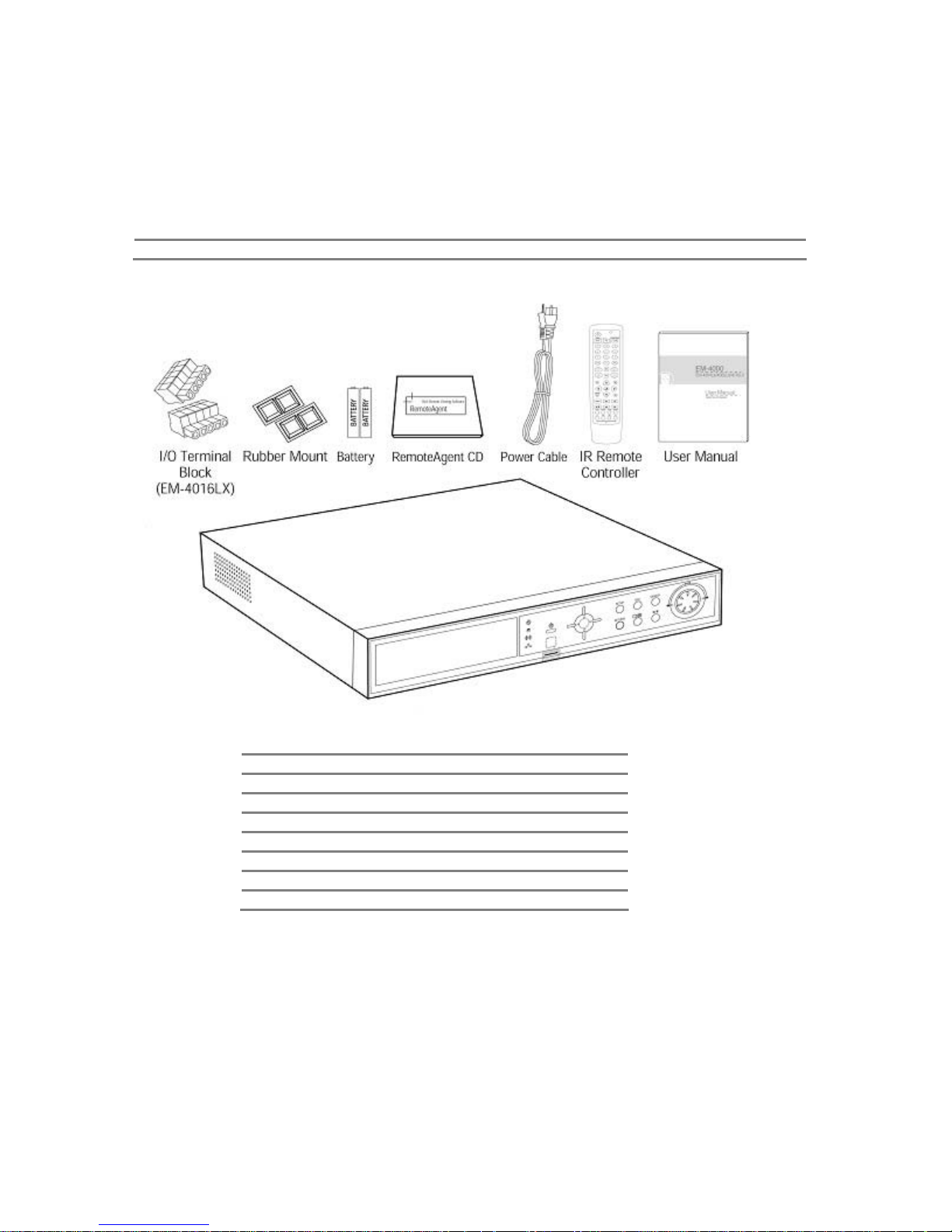
The following accessories are supplied with the VCD series digital video recorder. Keep the carton and
packaging materials for moving or storage purposes later.
Note If any of these items are missing or damaged, notify your vendor immediately.
Qty Accessories
1 User Manual
1 IR Remote Controller
1 Remote Agent CD
1 Power cable
2 Power battery (AAA Size)
1 Rack Mount Set
2 I/O Terminal Block
Page 10

2. Explanations for each function
2.1 Front Panel
The buttons on both the front panel of the VCD and IR Remote Controller have the same functions. Each
button can activate different functions. The main functions of each button are shown below.
1
No. Buttons Functions
1 CD-RW Backup the recording image by internal CD-RW. (Option)
2 Network LED LED is lit while the network client(s) (RemoteAgent) is connected to the system.
3 Alarm LED LED is lit when the sensor signal is inputted to the connected system.
4 HDD LED
5 Power LED Shows Power On/Off status of the system (GREEN: Working, RED: Stand-by).
6 USB Port USB interface Port to connect to external storage equipment.
Remote Control
7
Receiver
8 Power Button Use to turn the Power On/Off.
9 Select Channel
10 ENTER Button Use to enter detail menu, go into the next stage, select or set value.
11 RETURN Button Use to exit from the setting menu or to cancel setting value.
12 SETUP Menu to set user environment of the system.
13 Screen Mode Selection
14 SEQ Button Automatic time sequencing for monitor images.
15 Playback / Pause Playback recorded images/pause.
16 SEARCH Search recorded images
17 Shuttle Shuttle (outer dial): Speed up the playback speed of the image (2~32X).
18 Jog Jog (inner dial): playback frame by frame.
Shows if the camera image is being stored into or retrieved from the HDD (Hard
Disk Drive).
Receives input signal of the Remote Controller
The channel image will change when the corresponding up, down, left and right
button is pressed. This is same as using cursor key (direction key) on the main
screen.
Select the screen mode from 1, 4, 8 and PIP screen.
Page 11

2
2.1.1. CD-RW (Option)
The VCD series system can select the CD-RW as an Option. Use the CD-RW to backup the recorded image.
Refer to “Image Backup” for a detailed explanation.
2.1.2. Network LED
LED is blue when the system is connected to any network client (RemoteAgent). Light is automatically out
when all clients are disconnected.
2.1.3. Alarm LED
LED is lit if the system’s connected Alarm activates.
2.1.4. HDD LED
LED is blue when the camera image is being stored into or retrieved from the HDD. So, even though the system
is continuously recording, the HDD LED is only lit when actual data is recorded in the HDD. Usually, the LED will
be flickering, and this is normal.
2.1.5. Power LED
LED to show the power input and status of the system. The LED is red when the system is in stand-by
position, but is green when the system is working and power is being supplied.
2.1.6. USB Port
Used to backup recorded images on the VCD series by using a USB storage device. A system software
upgrade is possible with a USB storage device.
Note Refer to “Image Backup” for detailed explanation of USB storage devices supported by EM-3000 series.
2.1.7. Remote Controller Receiver
VCD can be operated conveniently, using the remote controller. Receives input signal from the remote
controller
2.1.8. Power Button
Connect the power cable of the product before pressing this button to turn the power on and off.
2.1.9. Select Channel
These buttons are used to change the channel images. The Left/Right button is used to change the channel
on 1- screen mode or PIP mode, and Up/Down button is used to change PIP channel from PIP mode. These
buttons are also used to move the cursor in the “Setting” mode, up, down, left, or right, and also to increase
or decrease the setting value.
2.1.10. ENTER Button
The [Enter] button is used to go to the next stage, select value or settings.
2.1.11. RETURN Button
Use to cancel the password just typed at the setting menu or return to previous menu.
2.1.12. SETUP
Set the environment of the VCD system according to the user requirement. Refer to “Setting” for detailed
explanation.
2.1.13. Screen Mode Selection
Screen mode can be selected from the monitor screen. Whenever the buttons is pressed, it will change in
sequence in 1, 4, 8 and PIP screen.
Page 12

2.1.14. SEQ Button
Press SEQ Button and the screen will automatically changes. Refer to “Settings” for automatic sequencing interval
(does not work on 4 split screen mode).
2.1.15. Playback / Pause
Playback recorded screen. The corresponding channel can be playback in 1 screen mode or PIP screen and all
the channels can be playback in 4 or 8 channels at once.
2.1.16. SEARCH
Search the recorded image by date and time. Refer to “Recording Image Playback Mode” for detailed image
searching method.
2.1.17. Shuttle
Jog/Shuttle dial is used to playback recording images. The inner dial is called Jog and the outer dial is called
Shuttle. The Jog/Shuttle dial has two kinds of functions. The Shuttle is used to speed up the playback speed
of images by turning it clockwise or anti-clockwise. Playback speed is indicated as x2, x4, x8, x16, x32 on the
lower end of the screen.
2.1.18. Jog
The Jog is used to find the recording image frame by frame. Turn the Jog dial clockwise or anti-clockwise
(only I-Frame is playback during anti-clockwise) to see the image frame by frame during the pause state.
3
Page 13
4
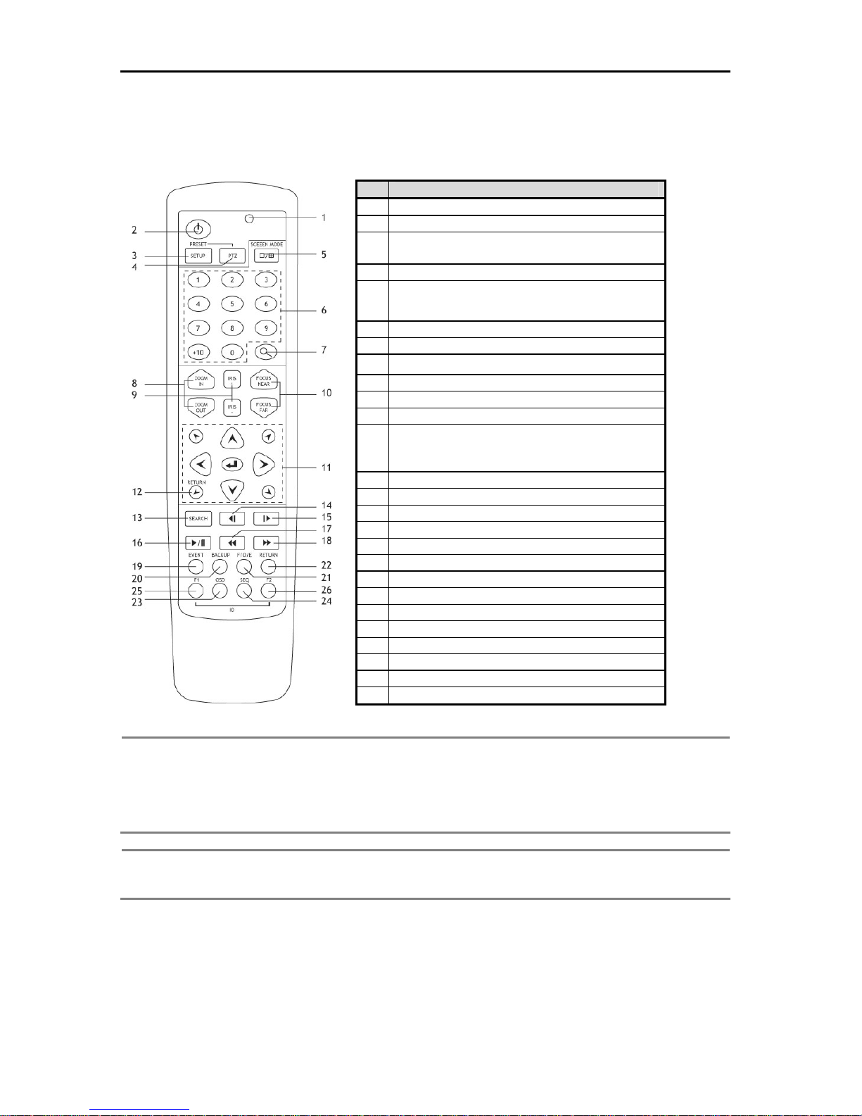
2.2 IR Remote Controller
The function buttons on the IR Remote Controller are the same functions on the front panel, as shown below.
Note F/O/E Button (use only on remote controller)
The object in the recorded image might show the feathering effect during frame playback because images at
704x480(PAL:704×576) resolution have higher vertical resolution than 704x240(PAL:704×288) or 352×240
(PAL:352×288). The feathering of the image can be solved when only one of two Fields (Odd, Even Field) is
selected. Default is frame playback. When the button is pressed, it will change to Odd Field Playback->
Even Field Playback-> Frame Playback order.
Note To use the IR Remote Controller, set the initial ID the same as the ID in SETUP-> RECORDER->
GENERAL->IR REMOTE CONTROLLER. The user requires setting the ID only once. Refer to the next page
for detailed information about ID input.
No. Functions
1 Activating LED
2 Power Button
SETUP (Use the Preset Button while using the
3
PTZ )
4 PTZ
Screen Mode Selection (1/4/8/PIPscreen sequence
5
button)
6 Number Input Button
7 Digital Zoom Button
ZOOM IN (enlarge) /ZOOM OUT(decrease)
8
9 IRIS+ (Open) / IRIS – (Close)
10 FOCUS NEAR / FAR
11 Direction Key
RETURN
12
(Use the 4 diagonal direction key button while using
the PTZ)
13 SEARCH Button
14 Playback Backwards Frame by Frame
15 Playback Forward Frame by Frame
16 Playback/ Pause Button
17 Fast Playback Forward Button
18 Fast Playback Backwards Button
19 EVENT Button
20 BACKUP Button
21 F/O/E Button
22 RETURN
23 OSD Button
24 SEQ Button
25 F1 (Use to enter ID)
26 F2 (Use to enter ID)
Page 14

Note Number Button
Change the channel on the 1-screen mode. Press the number buttons for 1~4 channels to see the
corresponding channels. Also used to set the setting value on the “Setup” menu.
Direction Key Button
The direction key activates differently for Realtime Image/Playback Mode, Setup Menu Mode, Search Menu
Mode and Digital Zoom Mode. The Digital Zoom Mode only activates in Realtime Image Mode, Recording
Image Playback Mode and 1-screen mode. Thus, change the screen to 1-screen mode to activate the direction
key.
On RealTime Image/Playback Mode On Digital Zoom Mode
Right Side Direction Key: Increase the channel on
screen
Left Side Direction Key: Decrease the channel on
screen
Up Side Direction Key Button: Increase PIP channel
on PIP Mode.
Down Side Direction Button: Decrease PIP channel
on PIP Mode
Setup Menu, Search Menu Mode PTZ Mode
Up, Down, Left, Right Button: To Move direction Up, Down, Left, Right Button: To Move Direction
Diagonal Direction Button: Return Diagonal Direction Button: To move Direction
2.2.1. Setting IR Remote Controller
As one IR Remote Controller can control several DVR’s, the ID will have to be assigned to use each Remote
Controller on each product.
The following method below is to set the ID on the IR Remote Controller. Default ID will be 00.
1. Insert the battery into the IR Remote Controller (AAA Size×2).
2. Press both [F1] Button and [F2] Button at once on the IR Remote Controller for more than 2
seconds.
3. Check whether LED of the IR Remote Controller is lit.
4. By using the IR Remote Controller’s number button, set the ID number between 00~99. Set the ID
number in 2 digits (ex. 03,55).
5. Set the ID of the system the same as the number set on the IR Remote Controller, by using front
panel direction key.
6. Press [OK] Button on the screen to save the set ID.
Note All the systems have the same default value ID when it is out of the factory. Therefore, when the default value
is used, one IR Remote Controller can control several systems at once. To prevent this, it is recommended to
set each ID for each system, as it is easy to change the ID for IR Remote Controller. Several systems can be
controlled separately by changing the ID of the Remote Controller whenever it is used.
Up, Down, Left, Right Button: To Move Direction
Enter (
Zoom In/Out Button: To Decrease or Enlarge
Screen
Diagonal Direction Button: Return
) Button: PIP Screen On/Off
5
Page 15
6
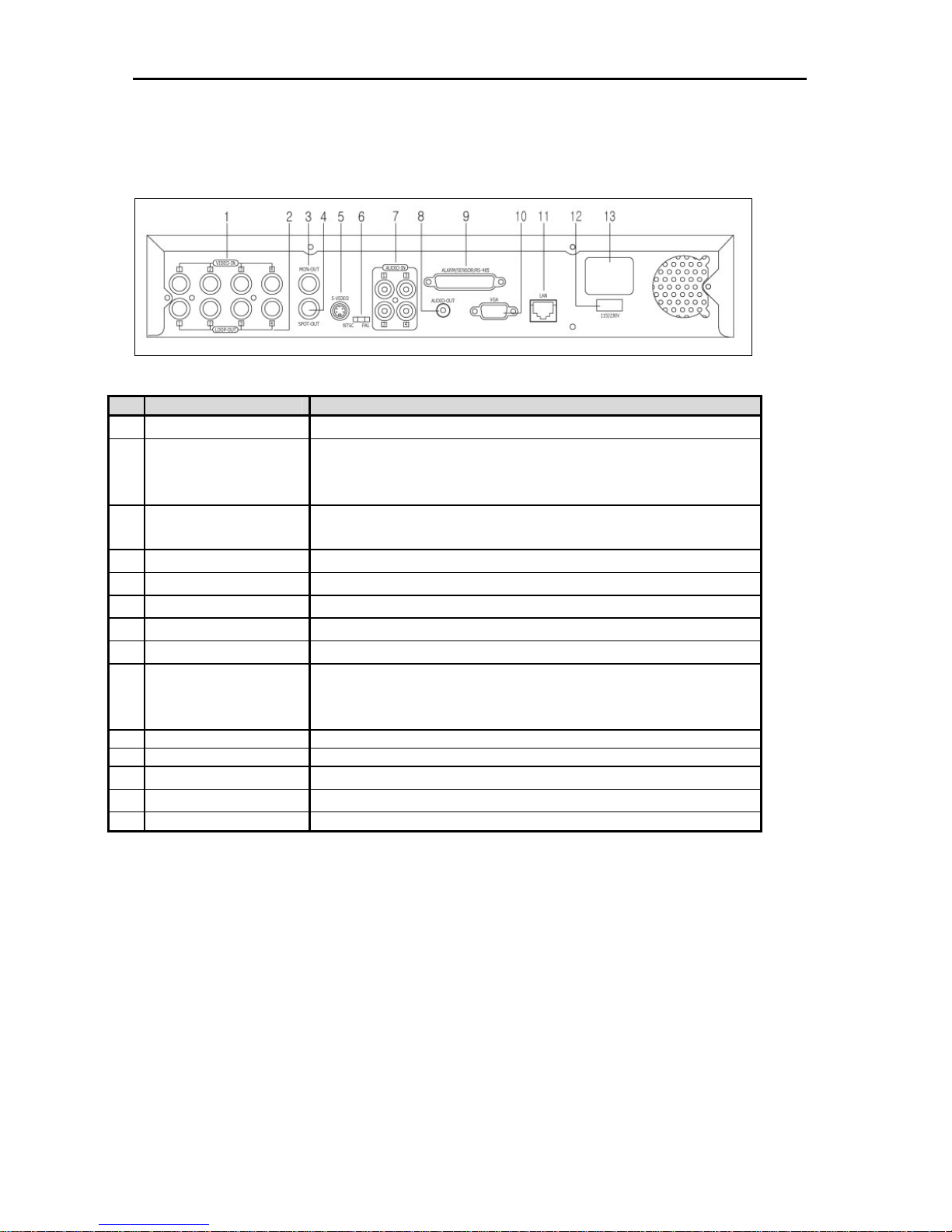
2.3 Rear Panel
The rear panel connections are shown below:
No. Name Description
VIDEO-IN (BNC) Connect camera. (Supports NTSC/PAL)
1
Camera images of each channel will be outputted as is. It is also used when
LOOP-OUT
2
MON-OUT
3
SPOT-OUT Used to output the entire surveillance screen one by one, in an interval.
4
S-VIDEO Connect to the S-Video input terminal to output the image on the main monitor.
5
Select NTSC / PAL Select the signal system. (NTSC / PAL)
6
AUDIO IN Connect Audio Input Device. (with Amp.)
7
AUDIO OUT Connect Audio Output Device. (with Amp.)
8
ALARM/ SENSOR
/RS-485
9
10 VGA Port Connect to the PC Monitor.
11 LAN Port 10/100 Ethernet connection terminals for remote connection.
Power Input
12
Power Switch
13
14 USB Port USB interface Port to connect to external storage equipment.
the corresponding image is required for other products (8 /16 channel has no
LOOP-OUT).
Connect to the main monitor for camera image for
surveillance/management/playback.
Use this terminal to connect external input sensors on channels 1~4. (Supports
N/O or N/C) Connect the RS-485 signal output, or the relay for P/T/Z camera
control.
Power cable connection terminal for connecting to the main power.
Switch to change input power. (115/230V)
Page 16

2.3.1. VIDEO-IN
Connect the BNC plug of the camera cable to the corresponding channel number’s image input BNC plate,
which is on the rear panel.
Note
Camera Input voltage level is 1Vp-p±10%.
2.3.2. LOOP OUT
Use to apply the video camera input to other devices. Without using a video distributor, the same image can
be connected to the camera input of other products. (Not applicable)
2.3.3. MON OUT
Connect the BNC cable of the monitor to MON OUT BNC cable of the rear panel.
2.3.4. SPOT OUT
The spot monitor can only be used to display input images in automatic interval (switcher) mode. Refer to
“Settings” for automatic interval time setting on the spot monitor.
2.3.5. S-Video Output
One additional main monitor can be installed by using the S-Video output. Use the S-Video cable to connect
the VCD with the monitor, which has S-Video Input.
2.3.6. Select NTSC / PAL
Turn off the power on the VCD series and select the NTSC/PAL switch correctly. Then turn on the power
again.
2.3.7. Audio In
Connect an Audio Input Device.
Note Input voltage of audio input device is line level.
Use of an audio output device with an amplifier is recommended.
2.3.8. Audio Out
Connect an Audio Output Device
Note Use of an audio output device with an amplifier is recommended
2.3.9. ALARM/SENSOR/RS-485
Connect sensor (dry contact type). Separate the terminal block and wire all devices to desired pins before
connecting the terminal block again. Connect each ground (GND) line to “G” pins.
Note Supports both N/O (Normal Open) and N/C (Normal Close). If connected sensor is not functioning, ensure
wiring is correct.
Connect various alarm devices controlled by relay output. The VCD series supports RS-485 for P/T/Z
control.
7
Page 17
8
Note The connection method differs according to the type of P/T/Z controller used. Inquire from your vendor if you are using anything
other than the RS-485.
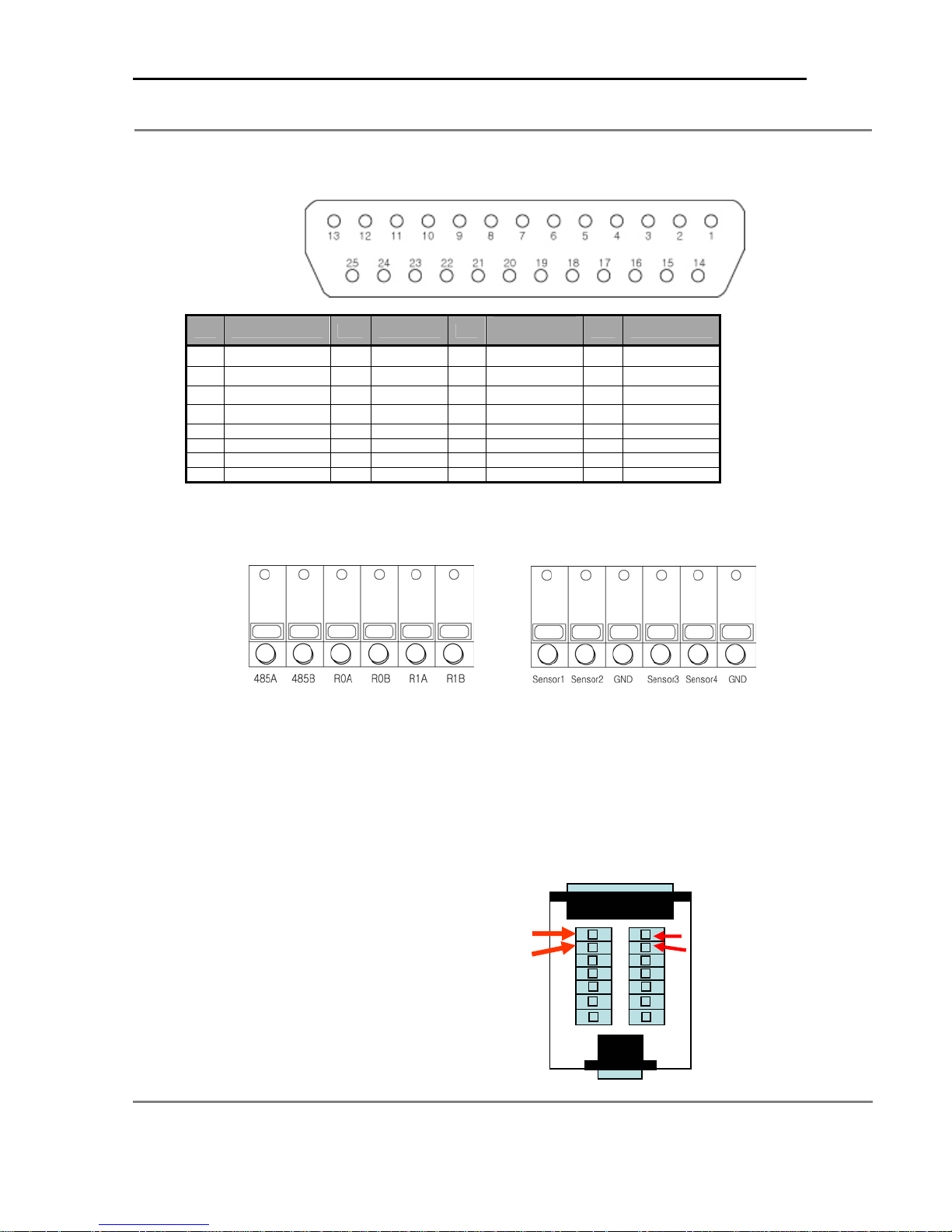
Refer to the picture below for printer port connection of the VCD 304/308 rear panel.
NO. SENSOR NO. RELAY NO.
SENSOR1
1
SENSOR2
2
SENSOR3
3
SENSOR4
4
14 SENSOR1-GND 18 RELAY1(-) 23 NO Connect
15 SENSOR2-GND 19 RELAY2(-) 25 NO Connect
16 SENSOR3-GND 21 GND
17 SENSOR4-GND
5
6
7
13
RELAY1(+)
RELAY2(+)
GND
GND
8 rs485-RX
20 rs485-TX
22 rs232-TX
24 rs232-RX
Serial
Communication
NO. NO Connect
NO Connect
9
NO Connect
10
NO Connect
11
NO Connect
12
Refer to the picture below for connecting I [I/O Terminal Block] to the Alarm/Sensor/RS485 port, which is at the back panel of
the VCD 316 system. First, connect RS485~R1B to the upper part and Sensor1~GND to the lower part.
[Upper part of I/O Terminal Block] [Lower part of I/O Terminal Block]
2.4 PTZ CONNECTIONS
Physical connections.
The RS485 connection supports up to 1000 feet. That will depend on your cable gauge and distance. You can use twisted
pair cable .If you have multiple PTZ cameras connect the data cable in parallel mode and make sure to assign different a
address ID to each one.
VCD304, VCD308. Alarm Block configuration
RS485B TX -
RS485A TX +
TX TX +
RS485B
RS485A
Page 18

VCD316. Upper port of I/O
Terminal Block
2.4.1. VGA Port
Use to connect a normal PC Monitor for local setup/surveillance.
2.4.2. LAN Port
Connect the RJ-45 jack of the LAN cable to the LAN port. The Network has to be TCP/IP base 10/100 Ethernet LAN (Local
Area Network), Internet or exclusive line, and the IP address should be fixed. Consult your network administrator for proper
network configuration.
2.4.3. Power Input
Connect to main power cord of the system.
Caution
2.4.4. Input Power Switch
Input power can be used in accordance with the user environment. Check input power before inputting power.
2.4.5. USB Port
Connect a USB storage device for image archiving or Firmware updating.
Before plugging-in the power cord to the system, check if the power is in accordance with the system
specification (Single Phase AC 115~230V)
TX+ TX-
RS485A RS485B
9
Page 19
10
3. Installation
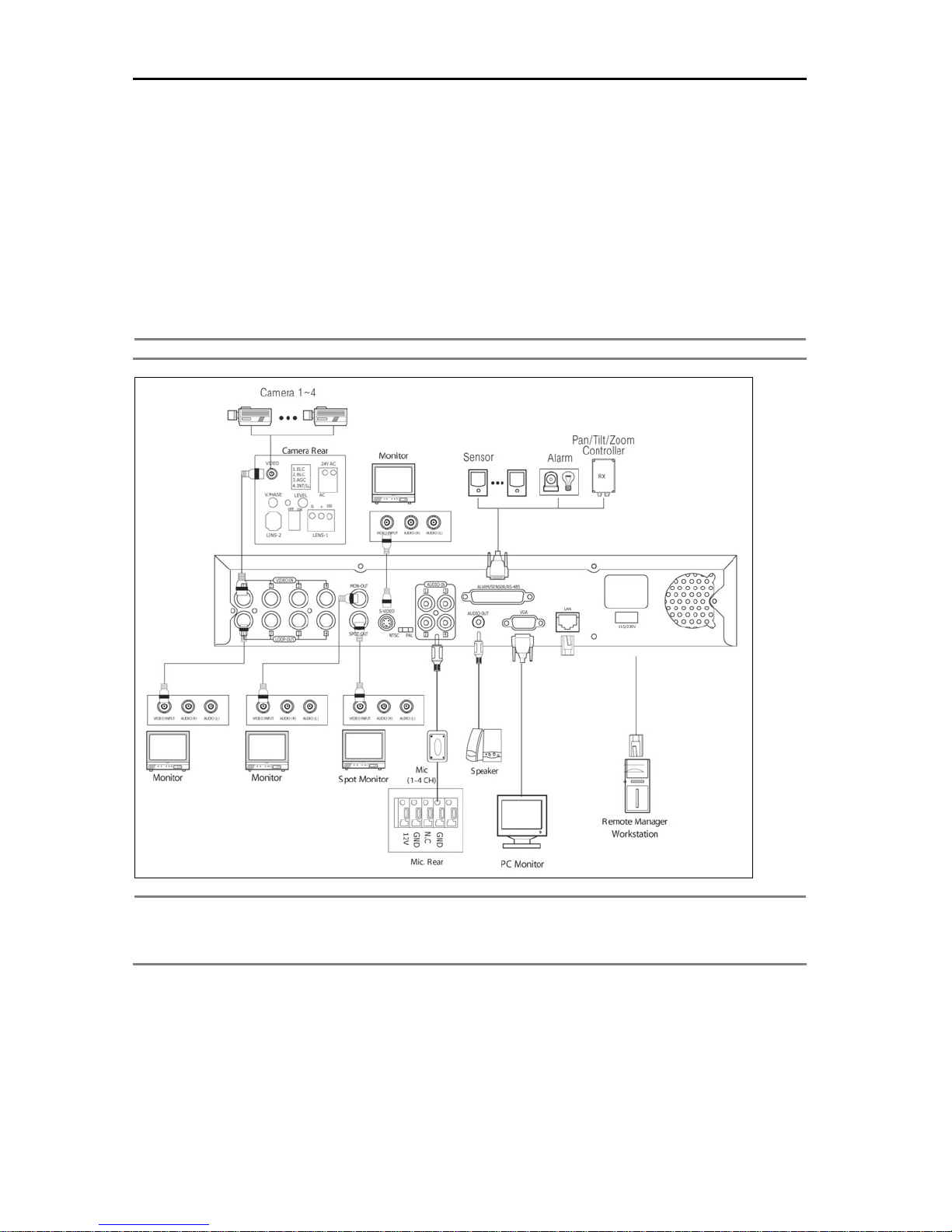
3.1 Connecting Peripheral Devices
This section describes how to efficiently hook up peripheral devices using with the VCD series. Below is a
picture showing the connection for the VCD series with the peripheral devices.
Install the VCD series on a flat surface. If required, attach a rubber mount for installation. If a 19-inch rack is used, it
is recommended to install the system on shelve and use 2.5~3U(1U=1.75 inch or 4.45 cm) space for proper
ventilation.
Note Install the system in location with good ventilation to prevent overheating.
Caution
Depending on the grounding, if the coaxial cable connecting to the camera has any risk or danger of electric
shock,. shutdown the power on the system completely (unplug the power cable) before connecting video
cable to BNC port.
Page 20
3.2 System Startup and Shutdown
3.2.1. System Startup
After connecting all peripheral devices, connect the power cord to VCD series for system startup. The power
will turn on automatically if there was abnormal shutdown, such as a power failure.
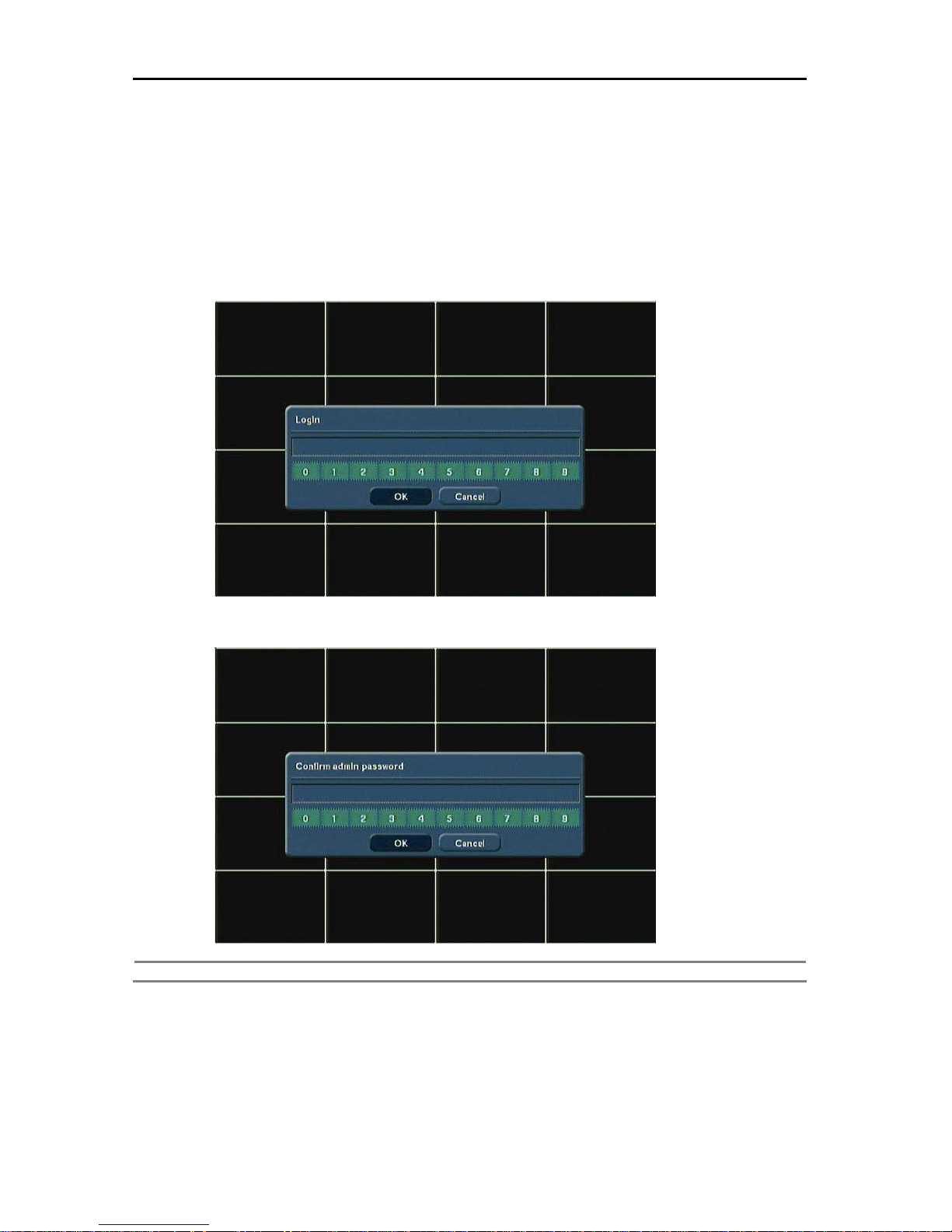
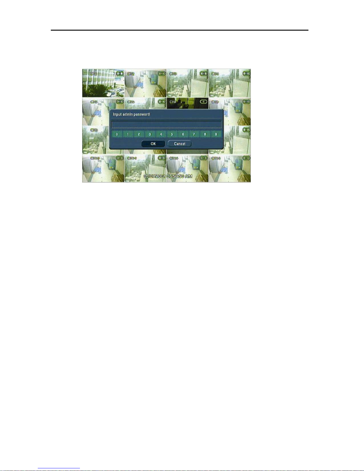
Register an admin. password after inputting the power and turning “ON” the system. This prevents others
from modifying the settings. If a password is not required, press [OK], without entering the password.
11
Enter the Password and press the [OK] button. Re-enter once more to confirm.
Caution Please write down your password and keep in a safe spot in the event that it is forgotten.
Page 21
12
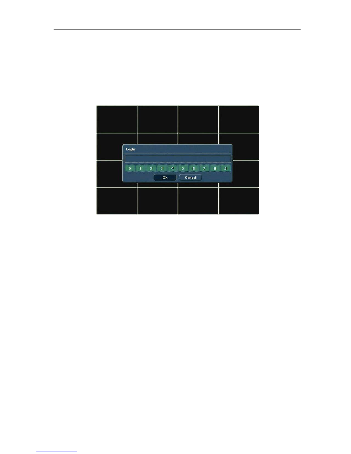
A screen asking for an admin. password will appear when the system power is turned on for the first time.
The Log In screen will appear. Several users can use one system, using different passwords. Refer to the
“Recorder->Password” for the user setting method.
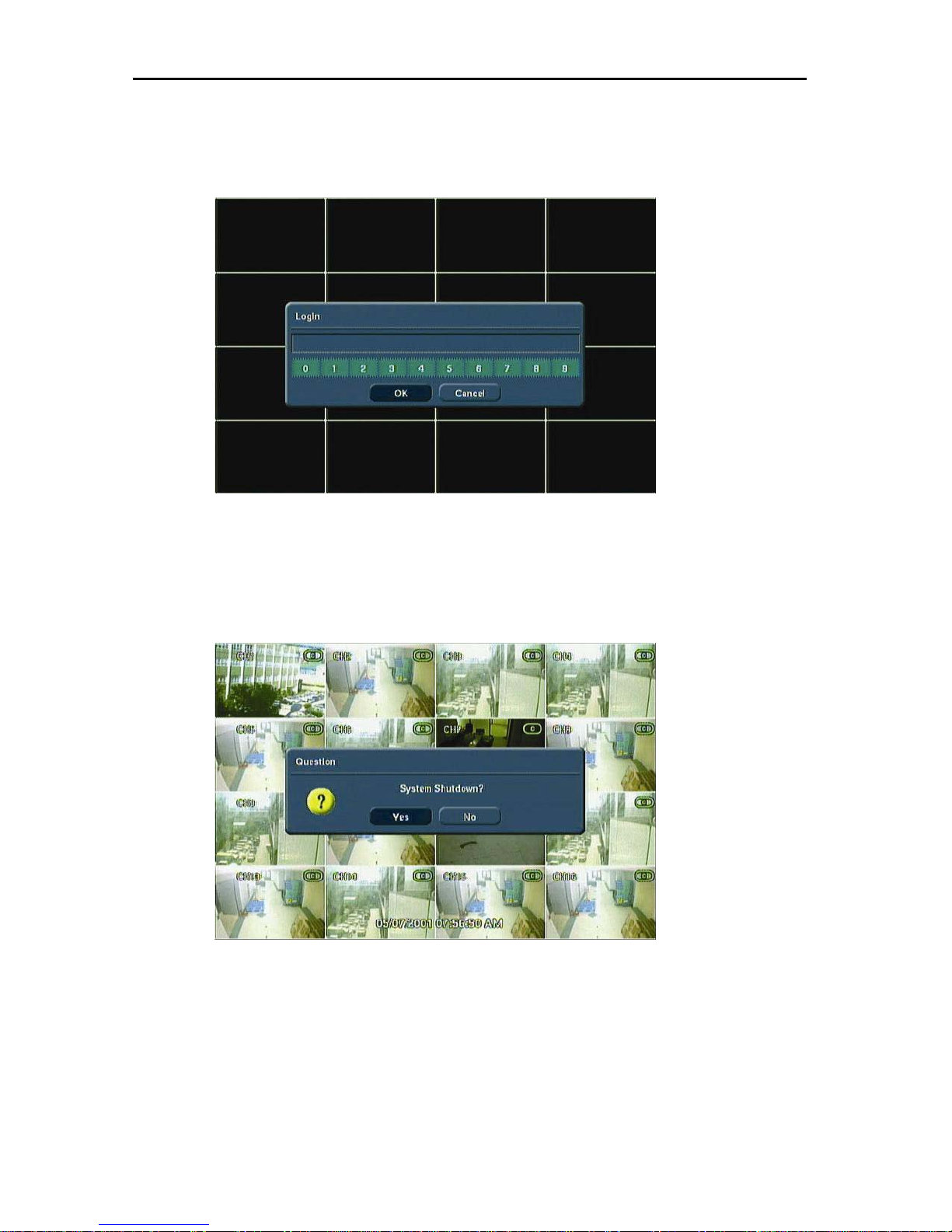
3.2.2. System Shutdown
To turn the power off, press the power button for proper shutdown of the system. Do not shutdown the power
by pulling the power plug.
The message below will appear when the [Power] button is pressed to shutdown the system.
Page 22
Press the [Yes] button and the confirmation admin password will appear. Enter the proper password and
press the [OK] button to shutdown the system safely.
13
3.2.3. Countermeasures after abnormal shutdown
VCD series has been designed to operate for long periods without a problem.
The operation of the system can be locked up, when major parts, (such as a hard disk) function abnormally due to
external electric shock, physical damage, or other various reasons.
The system stops operating during abnormal situations, and the internal watchdog circuit is activated in order to reset the
system for rebooting within 2 minutes. The system will then recover normally. It will also automatically reboot even when
there is a power failure. However, if major parts (such as a hard disk) are physically damaged, it is impossible to recover
normally. This will cause continuous rebooting by watchdog or deadlock without reset.
Countermeasures for abnormal discontinuation are as follows.
1. If the power cannot be turned off, turn off by pulling the power cord.
2. Wait for about 10 seconds and then reconnect the power. Ensure the system is functioning properly.
3. Consult your dealer if the system is not functioning properly after reconnecting power.
Page 23
14
4. Operation
4.1 Log In
The VCD series has various on screen menu settings. The administrator can set the system password and <User> to
prevent unauthorized changes to setting values and alteration to recorded files.
You must log in with your password to access the menu setup.
Page 24
4.2 Real time Live Mode
Real time live image can be seen by a simple button operation after inputting the power.
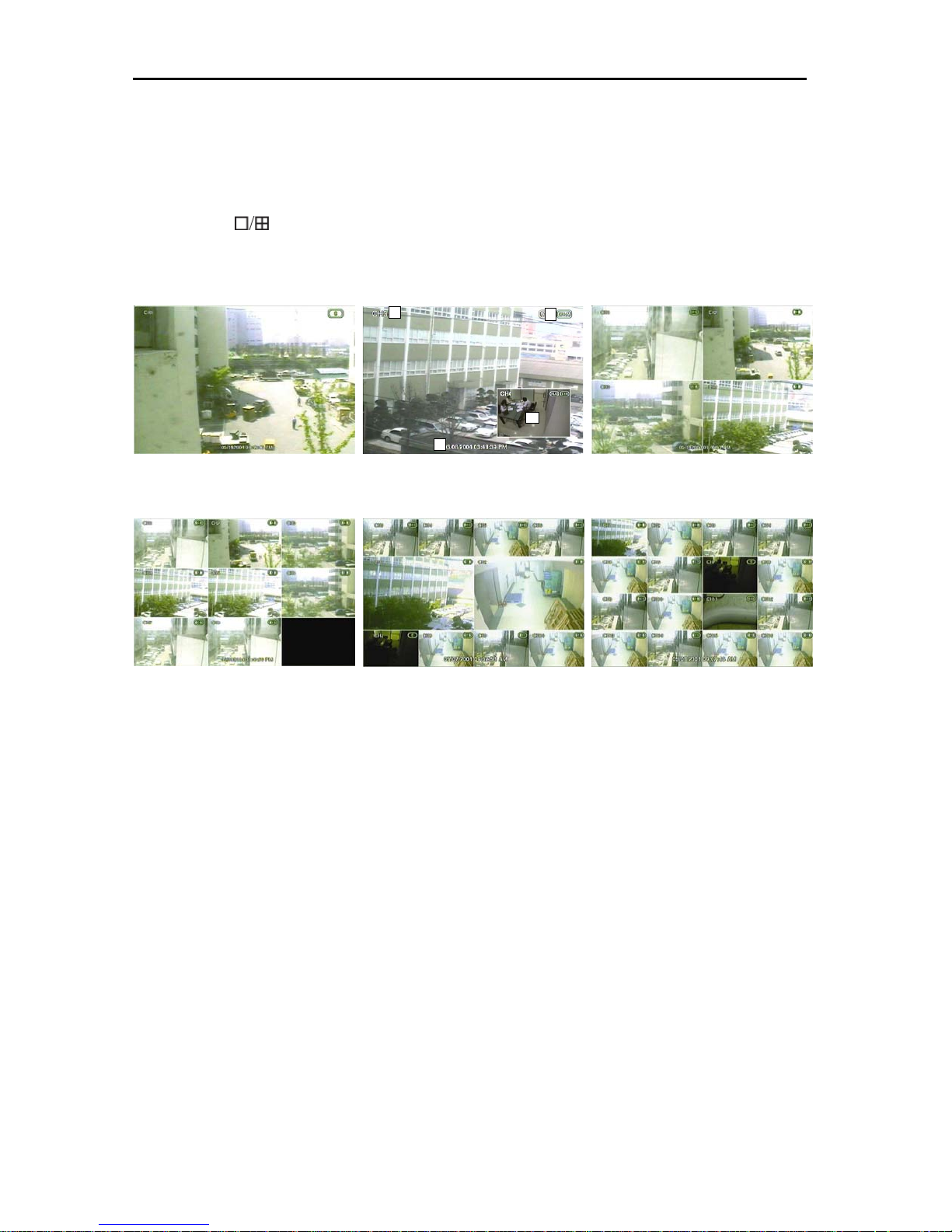
The images can be seen in real time by 1, 4, 9, 10, 16 and PIP screen. Whenever the button on the front panel or IR
remote controller [
change the channel from 1 screen mode, press the left/right arrow buttons on the front panel or IR remote controller.
4.2.1. Screen Configuration
] is pressed, the screen will change in 1 -> PIP -> 4 -> 9 -> 10-> 16 channels in sequence. To
1
2
4
15
3
[1 Screen Mode] [PIP Screen] [4 Screen Mode]
Above is typical screen with displayed items. Press the [OSD] button on the front panel or IR Remote Controller to control
the display of OSD. Whenever the button is pressed, the OSD display will toggle between appearance and
disappearance.
The following is the explanation of each item displayed on the screen.
1. Channel Name: Shows camera title of the location. Refer to “Setting->Camera-Common” to input camera
location.
2. Recording Status: Indicates present recording, recording mode, camera information, such as PTZ and icons for
activating motion and alarm according to the schedules.
3. Date and Time: Indicates present date and time of the system. When the recorded data is played back, it
indicates the date and time of the recorded time displayed.
4. PIP: PIP screen will be indicated as one of the multiple screens, and will appear when the digital zoom is used
in full screen mode. Digital zoom is used to enlarge or decrease the screen image size when the digital zoom
button of the remote controller is used.
Page 25
16
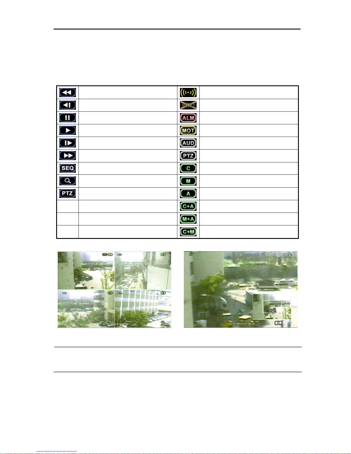
4.2.2. See Operating Status
In real time live mode, icons or messages will be indicated on the screen to notify the system mode or status.
Below are the icon categories, which are indicated on the monitor.
Fast Backward Playback
(Indicates Times:
Playback Backward Frame by Frame
X2, X4, X8, X16, X32)
Alarm
Smart Alarm. Pre-Alarm for HDD error
Stop / Pause
Playback
Playback Forward Frame by Frame
Fast Forward Playback
(Indicates : X2, X4, X8, X16, X32)
Automatic Screen Sequence
Using Zoom Function
Using PTZ Function
Alarm Activating Channel
Motion Detecting Channel
Audio Activating
P/T/Z Control Activating
Continuous Recording (c)
Motion Detection Recording (m)
Audio Activating Recording (a)
Continuous + Alarm Activating Recording
(c+a)
Motion Detection + Alarm Activating
Recording (m+a)
Continuous + Motion Detection Recording
While Alarm Activates
Note
When an alarm occurs in the connected channel, the [Alarm] icon will appear on the right bottom side of the
screen. To find out which camera had an alarm activation, go back to “ Live” and see the alarm icon
indicated on the right bottom side of each channel.
While Using Digital Zoom Functions
Page 26
17
4.3 Recording Image Playback Mode
To search recorded images of the VCD series, the user will require selecting the date and time to search data easily.
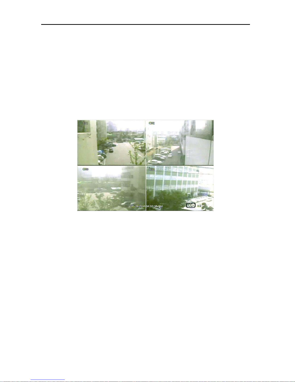
4.3.1. Playback Recording Images
To playback recorded images, press the Playback button from the Front Panel or IR Remote Controller. The latest
recorded image will begin playback.
It is easy to use the Front Panel’s Jog/Shuttle to playback recording files. Turn the Jog ring and the recorded files can be
seen backwards or forwards frame by frame. Turn the Shuttle ring and the playback speed can be controlled 2, 4, 8, 16,
32 times while playing backwards or forwards.
The below picture is when the playback speed is 2 times.
Page 27
18
4.4 Search Recording Image
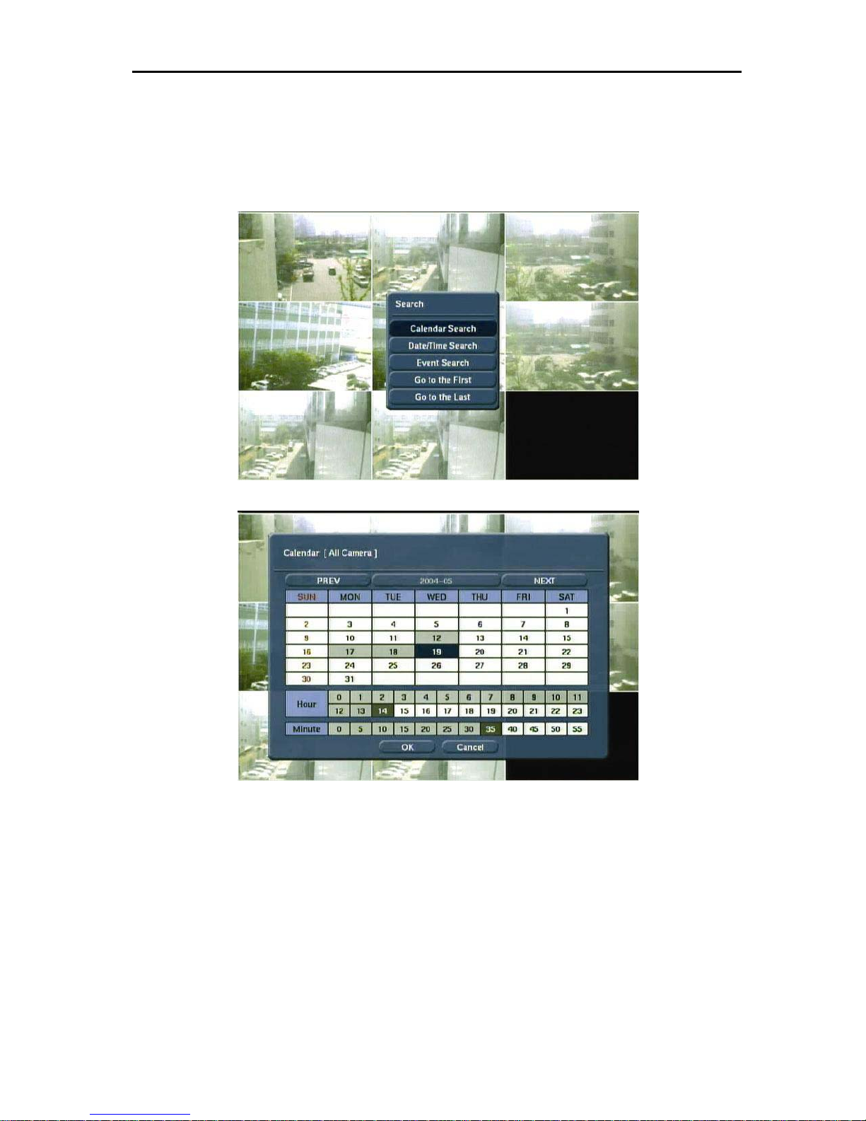
4.4.1. Calendar Search
The user can select date and time to search for a certain file within the recorded image. Press the [Search] button of the
IR Remote Controller and the Search Menu will be indicated on the screen below.
Below is the sequence to search date and time.
1. Select the date with recorded image by clicking the calendar with the arrow button. The date with the recorded
image will be indicated in gray.
2. Move the arrow button to the date desired before pressing the [Enter] button of the Front Panel or IR Remote
Controller.
3. Move the cursor to the time graph below for the desired hour range.
4. From the minute unit graph, select the minute.
5. Move the cursor and press the [OK] button, the recorded image for the corresponding time will be recalled by
the pause state. Press the [Play] button to see the playback of the recorded image.
Page 28
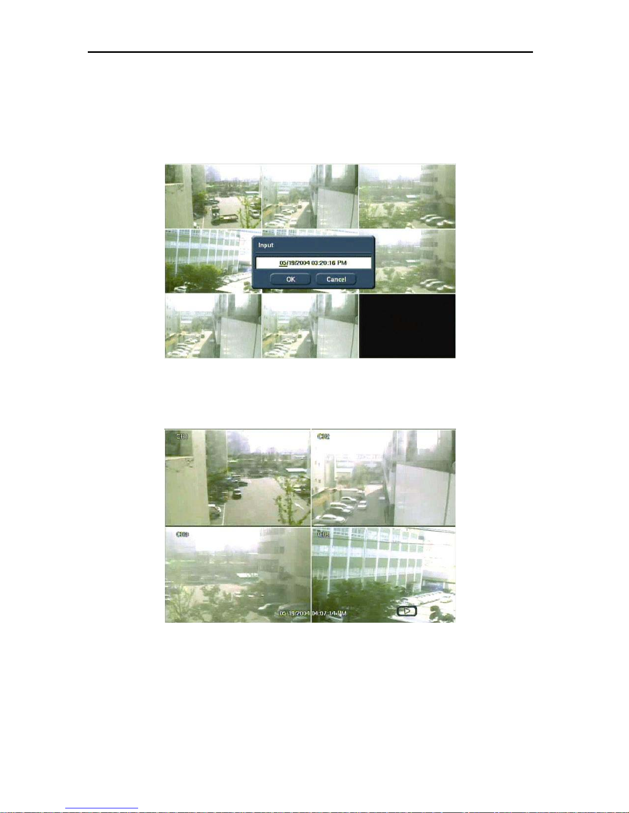
4.4.2. Search Date/ Time
Enter the desired date and time for the user to playback the recorded image.
Select [Search->Date/Time Search] category and the screen will appear as shown below.
Use the arrow button to move to each day/month/year and time (hour:min:secs AM/PM) category for entering date and
time.
19
Enter the date and time before pressing the [OK] button and the picture will appear as shown below to show the image of
the searched date/time. If the image does not appear and there is no recorded image, press the [▶ ] button to playback
the recorded images.
Page 29

20
4.4.3. Event Search
The Event Search function is used to find a particular event, quickly and easily.
To see a particular event of activated time, move the arrow button on the Front Panel or Remote Controller to the desired
time range.
The following categories may be indicated on the Event Viewer.
1. Alarm by Sensor
2. Alarm by Motion
3. Alarm by Video Loss
Select the time and press the [Enter] or [▶ ] button of the Front Panel or IR Remote Controller, to playback the image of
the time with activating event.
4.4.4. Go to the First
Go to the first screen of the recorded image. This is the oldest image recorded.
4.4.5. Go to the Last
Go to the last screen of the recorded image. This is the latest image recorded.
Page 30

21
5. Setting
To operate the VCD series system, appropriate setting values in the setting menu are necessary. Users can either input or
change the settings values listed in the table below.
Main Classification Sub Classification Setting Category Default
Resolution 352x240
General
Date & Time
Recorder
Backup
Disk Format
Passwords
Log Off
Common
Recording
Camera
Alarm Alarm In/Out
Schedule Select Camera
Color
PTZ
Audio
Sequence Dwell 3
Spot Dwell 3
IR Remote Controller 00
Language English
Date and Time
Date Format MM/DD/YYYY
Time Format AM/PM
Daylight Saving US
Device
From
To
Size
HDD Disk
Size
Admin
User1~5 / Default
Title CHn
Security Mode Off
Show Title Security
Auto Deleting None
IPS 30
Quality Standard
Sensitive 80
Area 전체 선택, (Tracking : Off)
Audio None
Record ON
Bright 0
Contrast 0
Color 0
Tint 0
Sharp 0
AGC On
Protocol None
Address 0
Audio On/Off Off
Two Way Audio Off
On/Off Off
Camera None
Out None
IPS 30
Mode Set
Dwell 5 sec
Pre-Alarm 0 sec
Type N/O
Page 31

22
Main Classification Sub Classification Setting Category Default
On/Off Off
Out None
IPS 30
Dwell 5 sec
Pre-Alarm 0 sec
On/Off Off
Alarm Out None
Dwell 5 sec
Pre-Alarm 0 sec
Smart Alarm On
Alarm Out 1
Dwell Time
Type LAN
IP Address
Subnet 255.255.255.000
Gateway 192.168.000.001
Mac Address
Band Width Limit
Dynamic IP Server 220.73.179.38
TCP Port 43300
UDP Port 11000
Notification Server
Email Notify
Email List
Host Name
SMTP Server
SMTP ID
SMTP Password
Signal System NTSC
Software Version
Firmware Version
Disk Usage
IP Address
MAC Address
Log Number
Log Type
Date/Time
Upgrade From CD-RW or USB
Device
Host Address
Current Version
New Version
Device
Current Version
New Version
Device
Current Version
Alarm
Network
System
Motion Alarm
Video Loss
Smart Alarm
IP Setting
Dynamic IP Server
Event Notification
System Information
System Log
System Upgrade
Import Setup
Export Setup
Factory Default
192.168.000.XXX
(MAC Address 최하위 값)
Page 32

5.1 Recorder - General
Set general user environment for the system.
23
Use the button of the Front Panel or Remote Controller to select the category, and press the [Enter] button. A detailed
menu of each category will appear.
5.1.1. Resolution
Select there solution for the recording image. The resolution is the required horizontal and vertical pixel number of a
pages. The resolution is indicated as (horizontal) X (vertical) pixel number. Select one setting from 352×240, 704×240,
704×480. Default is 352×240. As the resolution number increases, the picture quality is higher. In fact, 352×240 is the
VHS level. When a higher quality camera is used, 704×480 shows the DVD level picture quality. When the picture quality
gets higher, the storage capacity is bigger and the recording period will be shorter. Therefore, selecting the appropriate
resolution according to the situation is important.
Page 33

24
Note The storage capacity for the same image will differ. That is, images per byte is a ratio of the image dimensions
(horizontal x vertical), thus 704×240 is twice the size of 352×240 and 704×480 takes about 4 times the storage
capacity.
Therefore, when high resolution is selected for the same period, the storage capacity taken up will be larger,
and the storage period will be shorter on the same Hard disk capacity.
Note For the same resolution, the frame per byte size will vary according to the recorded picture quality setting,
movement, and complexity of the image and noise. Therefore, the total recording period will differ hugely
according to the image particularity.
352×240 : Standard Quality Standard 3~5KB
704×240 : Standard Quality Standard 5~10KB
704×480 : Standard Quality Standard 10~20KB
5.1.2. Sequence Dwell
When real time image mode is in automatic sequencing mode, set the time interval between each screen sequence.
Sequence Dwell function is for the user to select certain time intervals between each page.
For example, when a sequence function is activated on the 1-screen mode, the next screen will be shown in sequence
according to the set time interval. By pressing the [SEQ] button on the Front Panel or Remote Controller activation will
occur. Possible setting limits are 1~60secs, and the default is 3 seconds.
Press the [Select Camera] button and the following screen will appear.
The user can select automatic channel sequencing. Select [All], and all the channels will be selected. The user can select
the channels to see the screen sequencing by choosing the channel numbers from the Menu.
Page 34

5.1.3. Spot-out Dwell
Set the screen sequencing of the connected monitor, which has been connected to the product by external output.
Select setting are 1~60secs. The external output cannot use other functions except when seeing the image on the screen.
Press the [Select Camera] button and the following screen will appear.
The user can select the cameras to see as an external output. Select [All], and all the channels will be selected. The user
can select the channels to see the screen sequencing, by choosing the channel numbers from the Menu.
25
5.1.4. IR Remote Controller
An IR Remote Controller ID can control several units at once using one remote controller. Thus, an ID will be required to
set the control for each unit with one Remote Controller.
Below is the method to set the ID of the IR Remote Controller. Default ID is 00.
1. Insert battery into IR Remote Controller. (AAA Size×2)
2. Press the [F1] and [F2] buttons of the IR Remote Controller together for more than 2 seconds.
3. Check if the LED lights up on the IR Remote Controller.
4. Press the ID Number between 00~99 by using the number button of the IR Remote Controller (ex: 03, 55).
5. By using the direction key on the Front Panel, designate the ID number the same as what’s set on the IR
Remote Controller
6. Save the ID setting by pressing the [OK] button on the screen.
Note All the systems have the same ID as the default when it is out from the factory. Therefore, if the same default
value is used, one IR Remote Controller will control several systems at once. To prevent this, it is advisable to
set your own ID for each system. It is easy to change the ID of the IR Remote Controller. The user can change
the Remote Controller ID to control several systems separately.
Page 35

26
5.1.5. Language
The VCD series support multi-languages. According to the environment, the user can select several languages (presently
supports Chinese, English and Japanese). Select the language and the entire menu will change to the selected language.
The screens below shows that Korean and Japanese have been selected.
[Korean Menu Screen]
[Japanese Menu Screen]
Page 36

5.2 Recorder-Time & Date
Set the date and time of the system. Below is the setting method to set the date and time.
1. Use the up and down button on the Front Panel or IR Remote Controller to move to the desired category.
2. Press the [Enter] button on the Front Panel or IR Remote Controller to start editing.
3. Allocate the cursor by using the left and right buttons on the Front Panel or IR Remote Controller for editing,
and use the up and down button to change the value.
4. Press the [Enter] button on the Front Panel or IR Remote Controller to confirm the editing .
27
Page 37

28
5.2.1. Date and Time
Insert the exact date and time. Press the [Enter] button and the state will change to the input date. Input the time and date
of the system accurately, as it plays an important role in solving any problem with recorded image or event log.
The current time and date is stored in each recorded image with precision, as they are displayed during playback.
Be cautious that, if the time and date stored in recorded images are wrong, they cannot be altered afterwards, due to
encryption.
Note Users can change the time and date in the future without any problem. However, difficulty arises when
changing it to a previous date and time (the same files might exist in the hard disk). Therefore, under complex
record settings, unexpected problems might arise in the system.
Note When a long time has elapsed after setting the date/time, it can be distorted. To maintain the exact time, the
date/time setting should be set once a month.
5.2.2. Date Format
Set the date display format. Use the arrow button to select the desired format in the date display format.
5.2.3. Time Format
Set the time display format. Time format can be selected either by a 24-hour or 12-hour base (AM or PM).
5.2.4. Daylight Saving
Select the daylight saving time for each country. Daylight saving time setting is automatically processed when the country
is selected. Supported countries are displayed in the table below.
No. Country Representative Region No. Country Representative Region
1 None GMT 14 Italy Europe/Rome
2 Australia Australia/Melbourne 15 Mexico Mexico/General
3 Austria Europe/Vienna 16 Holland Europe/Amsterdam
4 Belgium Europe/Brussels 17 Norway Europe/Oslo
5 Brazil Brazil/East 18 Poland Europe/Warsaw
6 Canada Canada/Eastern 19 Portugal Portugal
7 Denmark Europe/Copenhagen 20 Russia Moscow
8 Egypt Egypt 21 Slovakia Slovakia
9 Finland Europe/Helsinki 22 Spain Europe/Madrid
10 France Europe/Paris 23 Sweden Europe/Stockholm
11 Germany Europe/Berlin 24 Switzerland Europe/Zurich
12 Greece Europe/Athens 25 UK Europe/London
13 Israel Israel 26 US US/Eastern
5.2.5. Time Sync Server
This is a function that synchronizes the time of the DVR to be exactly the same as the server, without setting the time for
each DVR. Tick the [USE] category and enter the server IP address of the connected server.
The time will be synchronized every hour.
Page 38

5.3 Recorder-Backup
There are two ways to backup a recorded date in the VCD series. The first method is using the CD-RW Drive (selected
specs) to backup by CD. The second method is using the USB external storage device for backup.
Use the CD-RW Drive or USB Device attached to the VCD series to backup the recorded images.
Press the [Backup] button on the IR Remote Controller and the following screen will appear.
Note The specifications on the CD-RW Drive will be shown differently, according to the model. Refer to the CD-RW
Drive manual for detailed information.
29
An error message will appear when the CD-RW is not installed or not properly connected.
Note Consult with your vendor if detailed information on the CD-RW is required.
Note The following is a list of media supported in the internal CD-RW of the VCD series.
CD-R :
Acer, AMT, CMC, Kodak, LeadData, Maxell, Mitsubishi Chemical, Mitsui, Nan Ya, Philips, Princo, Prodisc,
Ricoh, Ritek, Sony, Taiyo Yuden, TDK, Verbatim, Yamaha
CD-RW :
Acer, AMT, CMC, Digimaster, Maxell, MaxMax, Melody, Mitsubishi Chemical, Philips, Plextor, Prodisc, Ricoh,
Ritek, Sony, TDK, Traxdata, Verbatim, Yamaha
Page 39

30
Enter each item on the screen below to backup recorded images.
1. Select the record start time for backup.
2. Select the record end time for backup.
3. Select the channels to backup. The user can select several channels together, but if the backup data capacity is more
than the storage capacity, backup will not proceed. Select the channel by using the cursor and pressing the [Enter]
button.
4. Select Viewer to write the Viewer program to the CD. Files created in the backup program can be viewed in either the
Viewer or in Remote Agent.
5. After selecting all the items, press the [OK] button to proceed to the next screen.
The backup program will:
• Extract the file for backup.
• Copy the file to a backup device.
Page 40

When the backup has been done properly, the message will appear below.
31
If the operation was canceled during backup, the error message will appear. below
Page 41

32
If the CD-R Media (Blank CD) for backup has not been inserted on the drive, the following error message will appear
below.
If the space of the CD-R is too small, or the storage capacity is too huge, the following error message will appear.
You can prepare a larger capacity CD-R or decrease the time of the backup image.
Page 42

5.4 Recorder-Disk Format
Supports the attached HDD format of the system.
Note The HDD format is not supported by the HDD that’s in use, as surveillance will be vulnerable.
Select the Disk Format category and the following screen will appear.
Select the HDD to format and check the capacity. Press the [OK] button and the formatting will proceed.
33
The HDD cannot be formatted when there is only one. It can be formatted when the HDD is installed for the first time.
An error message will appear below, preceding the format. Thus, check the user and installation status.
Page 43

34
5.5 Deleting hard drive data and setup configuration
Note: This feature is available from firmware version 1.14 or above.
Procedure
1. On the front panel press the left arrow and the Screen Mode Selection button
For more information see page 2..
2. A menu will appear on the screen asking to enter your admin password.
simultaneously.
Enter your admin password and press OK
3. Select YES to continue or NO to stop the procedure.
QUESTION
DO YOUR WANT TO DELETE ALL THE SAVED DATA?
YES NO
4. The last screen will show the following information:
VIDEO & AUDIO
SETUP
DELETE CANCEL
DATA FILES
OPTIONS
a. VIDEO & AUDIO. Check on the Video & audio option to delete data from the hard drive (s)
If this option is selected, the unit will take some time to delete all the files. The time will depend on the hard drive size
and the amount of data
b. SETUP . Check on the SETUP option to delete the DVR configuration.
If only the setup is selected, it will take about a minute to complete the process and the unit will restart when finished.
Once the unit has restarted, the DVR will ask you to enter a new password and click OK.
Page 44

35
5.6 Recorder-Passwords
Set the system passwords for <Admin> and <User>. <Admin> can do the setting for the password only. Each user has to
input a designated password to log-on the system. Set the password after selecting the [Admin] and [User] by pressing
the arrow button.
5.6.1. User
Select the user to set the password. The administrator can select the <User> password and the entire category. The
maximum number of <User> is five (5), and the settings can be done differently for all.
5.6.2. Password
Select the password to change the maximum number of characters to four (4). The following screen will appear below
when the [Enter] button on [New] category is pressed. Enter the desired password and press the [OK] button to save.
Note To go inside the editing state, use the [Enter] button on the Front Panel or IR Remote Controller and insert the
number by using the number button on the remote controller. After the editing is finished, to enter the password,
use the [Enter] button on the Front Panel or IR Remote Controller again.
Page 45

36
Press the [Enter] button and the color of the password input box will change. Use the number button to move the cursor,
and press the [Enter] button before inserting the number.
To insert the password by using the remote controller’s number button, press the [Enter] button on the input column. The
column will change to white, and a password can be set by using the number button.
Page 46

Enter a new password.
37
After entering the password, re-enter the same password again.
Page 47

38
When the entered password is complete, a message will appear informing you that the password had been entered
successfully.
An error message will appear when the password is inputted incorrectly. After setting the password, do not forget to inform
other users.
Page 48

5.6.3. Authorization
This is the category to set the authorization of the <User>. The admin. can use the entire category, but the settings can be
set differently, depending on the <User>. Press the [Permission] button and the following screen will be displayed.
Select categories used by each user and press the [Enter] button to check the categories.
39
The authorization of each category is as following.
1) Power Off : The power of the system can be on and off.
2) Playback : Recorded image can be played back.
3) Setup : Each category can be set at the system setup.
4) Camera : Only selected camera images can be seen, depending on the <User>.
5.6.4. Default screen is all cameras are un-checked
The image of the camera can be shown on the screen once the user login is selected. Press the [Authorization] button
and following screen will appear. The user can check on the desired camera number. It will be applied after the login and
the chosen images of the cameras can be seen. Select [All], and all the cameras will be selected.
Page 49

40
5.7 Recorder-Log Off
Log-off <User>, who has been Log-on presently. Log-on by entering <User> or <Admin> authorized password, to activate
system or to go inside the setting menu again. You must Log-off after changing the setting values so that no unauthorized
activation can be done.
Log-off prevents admin. and user from using.
Press the [Power] button on the Front Panel or IR Remote Controller to shut down the system.
Page 50

5.8 Camera-Common
41
5.8.1. Title
Input the camera title of the selected camera. The inputted camera title is displayed on the OSD (On-Screen Display) and
is also displayed on the recorded files. When the file is played back on the system or remote site, the camera title will be
indicated on the image file during playback.
The default camera title is “CHn” where n is the channel number. A maximum of 15 characters can be inserted, including
capital/small letters, numbers or spaces.
To move to the next group of channels, press the [1-8] or [9-16] buttons.
Page 51

42
The following screen shows a virtual keyboard to input letters.
The VCD series supports Multilanguage and special letters to input the camera name. There are language and special
letters to input on each page.
The following method is used to input each language and special letters.
1) Check the channel to input camera name.
2) When the [UP] button is pressed, the page no. will go up. On the [Up] row, press [1] button and it will go up by one
page, press the [10] button and it will go up by 10 pages, press the [100] button and it will go up by 100 pages.
3) Press the [Last] button and it will move to the last page.
4) Press the [Space] button to have space between letters.
5) The page number will go down whenever the buttons on the [Down] row is pressed. It is same as using the buttons on
the [Up] line.
6) The [<-] button is pressed to erase the inputted letters.
Note Refer to “ Appendix” for Multilanguage and special letter on each page.
Page 52

5.8.2. Security Mode
Set the security mode of the image screen. When this mode is set up, the image cannot be shown on the monitor. If the
recording is set; recording will be in progress, but will not be shown on the monitor.
5.8.3. Show Title
<Security Mode> or <Channel Name> can be selected, to be indicated on the monitor screen.
The picture below shows the set screen.
1) : [Security Mode : On], [Show Title : Security]
2) : [Security Mode : On], [Show Title : Hide]
3) : [Security Mode : On], [Show Title : Show]
4) : [Security Mode : Off], [Show Title : Show]
43
1
3
5.8.4. Auto Deleting
Set recording periods for each channel. Recording periods can be set from a minimum of 1 day to a maximum of 30 days.
If the recording period is set as 30 days, the data after 30days will be deleted automatically. When 1 day is selected, it will
be applied to the next day. To save the data for a long period, you must backup the data before automatic backup occurs.
Note The recorded data will not be deleted until the disk space is full, when it is set as None.
2
4
Page 53

44
5.9 Camera-Recording
Set the desired environment related to the camera’s usage. The screen below shows the settings related to the
recordings.
5.9.1. IPS
Set a frame per second for recording an image connected to each camera. This cannot exceed NTSC: 30fps, PAL: 25fps.
The remaining frame number is indicated at the bottom left of the screen whenever the frame number of each camera is
modified.
5.9.2. Quality
Set the recording quality for the corresponding channel according to resolution set. The picture quality can be selected
from 4 options: Highest, High, Standard, Low.
The setting value directly influences the byte size per image. For example, the byte size decreases as quality goes lower.
In this case, blocking (mosaic) phenomena tends to appear, which the artifact is caused by high compression. In contrast,
blocking phenomena disappears as quality goes higher. The required storage space per image increases, which leads to
the shortening of the total recorded period. Therefore, consideration should be given to the recording period, importance
of each camera image, and the quality of analog signals when setting the recording quality. If extending the recording
period in high quality, refer to the next explanation on Sensitivity. The byte size decreases when the sensitivity setting
decreases.
5.9.3. Sensitivity
Set the motion sensitivity value based on motion detection between 10~100. As the value gets higher, the movement will
be saved without skipping. As the value gets lower, the value skips small movements to extend the recording period.
The default is 80, and it is recommended not to change, with the exception of special cases.
Page 54

5.9.4. Area
Set the motion detection area. The default value is selected as an entire area when the motion detection area is selected.
The movement will be detected according to the area selected. Motion detection will not be done if the area is not set.
.
45
Set the area by using the direction key on the Front Panel or the IR Remote Controller. The method to set the area is shown
below.
1) Use the cursor to move to the area for setting on the screen.
Page 55

46
2) Press the [Enter] button and the color of the cursor will change. Use the direction key to increase the setting area.
3) Once the setting area is completed, press the [Enter] button for confirmation.
4) Press the [OK] button to save the contents of the settings.
5) Once the area is set, the box will be checked as the picture above.
Page 56

6) To set the row and line press the green box on the screen corner.
47
7) To set the entire area, press the left bottom corner of the screen.
5.9.5. Tracking
Traces and indicates the movement detected on the area set. A yellow box will be indicated on the screen, whenever
there is movement on the live display screen. Recording will not be influenced even though the [Tracking] function is not
used.
5.9.6. Audio
Select the audio channel to use among the 4 audio input channels.
Note
Use an amp-equipped device while connecting to the audio input/output device. Although audio is mapped from
this menu, audio recording cannot be done if the audio is not “ ON” from Camera-> Audio.
5.9.7. Record
Controls whether to record the channel connected or not. If recording is not required on the selected channel, even when
the camera signal is inputted, you should set the recording of the corresponding channel [OFF]. Recording of the channel
stops without pulling the camera BNC cable out. [ON] or [OFF] can be selected. The default is [ON].
Page 57

48
5.10 Camera-Schedule
Set the recording schedule for each camera. Select the camera to set the schedule.
The following picture shows the status of schedule setup for all cameras. The number indicates the time.
Recording schedule can be set per hour. The “initial” indicates the status of recording. The status of recording will be
displayed on the upper right of each channel when the live channel is seen.
The contents for each initial is as following.
1) c: Continuous : Continuous recording
2) m: Motion detection : Motion detection recording
3) a: Alarm-activated : Alarm-activated recording
4) ca : Continuous + Alarm-activated recording
5) ma : Motion detection + Alarm-activated recording
6) cm: Continuous + Motion detection recording
Note 1. If the recording is done with ca or ma, the recording will be recorded in continuous or in motion detection.
When the alarm activates, concentrated recording will be done according to the set IPS on the alarm.
2. If cm recording is done, the motion alarm must be turned On in order to record at the IPS set in the
motion alarm menu (SetupÆAlarmÆMotion Alarm). See Appendix II 8.5 for details.
Page 58

After pressing the [Holiday Setup] button, the screen below will be displayed.
Use this function when assigning other holidays, other than Saturday and Sunday. The method to assign a holiday is as
followings.
1. Move cursor to 01/01 (month/day) on the center of bottom.
2. Put the cursor in the number section and input the month/date by pressing the [Up] and [Down] button on the
Front Panel or IR Remote Controller.
3. After inputting the desired holiday date, press the [Add] button on the right side.
4. Check whether the assigned date has been inputted on the screen.
5. To move the screen, use the [Up] and [Down] buttons.
6. Close the screen by pressing the [Close] button and enter the schedule setup screen.
It will be included under Sat in Hol category when it is holiday. Set recording schedule from the category.
49
Page 59

50
5.11 Camera-Color
Set the brightness, contrast, color and tint of the connected camera. Each setting value can be set – or + value from the
present value.
5.11.1. Bright
Adjust the brightness (shades) of the channel. If the entire image is dark or bright to a great extent, adjust to the value.
Page 60

5.11.2. Contrast
Adjust the contrast, which is a ratio of brightness to darkness for the image. Greater the value; bright side becomes
brighter, and dark side becomes darker. If the value is increased to the extent where too much saturation is not observed
in the image, higher contrast can be helpful to display the image vividly.
5.11.3. Color
Adjust the color density. In most cases, except for the deterioration of cameras or very low quality cameras, the
adjustment of this value is not required.
5.11.4. Tint
Set the color hue of connected cameras. In most cases, except for the deterioration of cameras or very low quality
cameras, the adjustment of this value is not required.
5.11.5. Sharp
Increase the clarity by increasing the sharpness of the image. It is efficient when objects blur, but it is not recommendable
to use the setting value too high, as the picture quality will become lower.
5.11.6. AGC
This function increases the signal automatically in dark places, to brighten the picture. When it is OFF, the image will be
shown as it is, and when it is ON, it will make a great change on the picture.
51
Page 61

52
5.12 Camera- PTZ
Set the camera audio and P/T/Z environment.
5.12.1. Protocol
Set the protocol to control the P/T/Z controller connected to P/T/Z port on the back panel. P/T/Z controller is also called
receiver or RX if it becomes separated from the camera. Default is NONE, which indicates that the P/T/Z controller
protocol is not set. The protocol currently supported is shown below.
1 Ernitec 2400 baud rate no parity 8bit 1 stop bit
2 Kalatel 9600 baud rate no parity 8bit 1 stop bit
3 Panasonic 19200 baud rate no parity 8bit 1 stop bit
4 Pelco D 2400 baud rate no parity 8bit 1 stop bit
5 Pelco P 4800 baud rate no parity 8bit 1 stop bit
6 Scc-641 9600 baud rate no parity 8bit 1 stop bit
7 Sensormatic 2400 baud rate no parity 8bit 1 stop bit
8 Smart Scan 9600 baud rate even parity 8bit 1 stop bit
9 VC_C4 9600 baud rate no parity 8bit 1 stop bit
10 Vicon 4800 baud rate no parity 8bit 1 stop bit
New protocols added from firmware version 1.14 and above .
11 DXR-500 9600 baud rate no parity 8bit 0 stop bit
12 MRX-1000 9600 baud rate even parity 8bit 0 stop bit
13 Phillips GS 9600 baud rate even parity 8bit 0 stop bit
14 AN200 RS-232C 9600 baud rate no parity 8bit 1 stop bit
15 AN300 RS-232C 9600 baud rate no parity 8bit 1 stop bit
Speed Dome
16
Communications
17 SCC-931T 9600 baud rate even parity 8bit 0 stop bit
18 SRX-100A 9600 baud rate even parity 8bit 0 stop bit
19 SRX-100B 9600 baud rate even parity 8bit 0 stop bit
20 WDS-2308/2508 9600 baud rate no parity 8bit 0 stop bit
Set the controller address correctly for each channel after setting the protocol.
9600 baud rate no parity 8bit 1 stop bit
Page 62

5.12.2. Address
Set the P/T/Z driver address of the connected camera.
Check the below items for proper P/T/Z operation.
1. Check if the protocol of all P/T/Z controllers connected to the system are in accordance.
2. Check if the communication setting, including baud rate of all P/T/Z controllers are in accordance with the assigned value
for that P/T/Z protocol.
3. Check if the address of all controllers are in accordance with the controller address assigned in the setting menu for
that channel.
4. Check if the power of the P/T/Z controller is turned on.
5. Check if the wiring to P/T/Z controllers are correct.
53
5.13 Camera- Audio
Select whether or not to use audio recording. Select On/Off in the audio section for each camera.
To use the audio function, connect the audio system (speaker and microphone) when setting the system.
5.13.1. Two - Way Audio
The Two - Way Audio function is to hear voice and talk from both sides of the system and RemoteAgent. The Two - Way
Audio function can be used only on one channel from the entire channels available. When the Two Way Audio function is
used, the audio will not be recorded, even though the channel’s Audio category has been set to record.
Note Speaker and microphone should be set up in the connecting system, and the PC connected to the RemoteAgent.
Page 63

54
5.14 Alarm In/Out
This is the setting menu screen for the alarm-activated recording and camera, connected with the VCD series system.
5.14.1. On/Off
Select whether or not to activate the alarm. Press the [Enter] button and select On/Off.
5.14.2. Camera
Select camera channel number to connect with the alarm.
When the sensor activates, the image of the corresponding camera image will be recorded according to the frame set.
Recording time of the sensor changes according to the sensor type and alarm schedule. It will change back to the
previous status when recording is done.
Page 64

5.14.3. Out
Select the connected number (1,2 or None) to use for activating the alarm.
5.14.4. IPS
Set the desired number of frames for the recording of the connected camera. Set the number of frames according to each
camera. When a, ca, ma has been set on the schedule, the recording will be done according to the frames set on the IPS.
5.14.5. Mode
Select either Set or Duration depending on the desired alarm action.
Set:
Once the sensor is detected in this mode, the camera will be recorded according to the frames set during the setting time
in the Dwell tab. That is, recording will be done during the Dwell period from the sensor input activation, even if the sensor
is cut off.
Duration:
In this mode, the alarmed camera will be recorded while the sensor is activated.
Whenever the sensor is detected, the channel starts recording while other channels in the group stop recording. When the
relay (output) for the sensor has been set, it will activate together with the sensor.
5.14.6. Dwell
Set the recording period from the start of the sensor input activation. During this period, the corresponding camera image
will record according to the frame and alarm (relay) output set. The recording stops and the alarm output is turned off
when the setting period has elapsed. Set the alarm-operating period (1~99 seconds).
5.14.7. Pre-Alarm
Set the recording time before perceiving the sensor input. Pre-Alarm time is the opposite of Dwell time. It intensively
records the time before the alarm activates.
For example, If the Pre-Alarm is set for 20 seconds. If the alarms activates at 14:30:00 on 14th of February, the recording
starts from 14:29:40 on 14th of Feb.
5.14.8. Type
Select the sensor type between N/O(Normal Open) and N/C(Normal Close), connecting to the alarm input plate. The
circuit of the N/O type is usually open, and the activation of the sensor occurs at the time it is closed. The N/C type works
the reverse way.
55
Page 65

56
5.15 Alarm-Motion Alarm
Set the alarm activation, recording frame and time for motion detected on the camera image. This can be set while using
the Motion Alarm.
5.15.1. On/Off
Select whether or not to activate the motion detection alarm for each channel.
5.15.2. Out
Select the connected number (1,2 or none) of outputs (relay) to use when the alarm activates.
5.15.3. IPS
Set the number of frames for the camera image connected while the alarm is activated. Each camera can be set for a
different number of frames.
5.15.4. Dwell
Set the period of recording when motion ends after motion activates. This is different from the Dwell time in [Alarm In/Out]
category. The Dwell time in [Motion Alarm] category is a period of recording from the point when the motion disappears
after motion activation.
5.15.5. Pre-Alarm
Sets recording time just before perceiving alarm input. The Pre-Alarm time is the opposite of Dwell time, and records the
time before motion activation.
For example, Pre-Alarm is set as 20 seconds. If the alarms activates at 14:30:00 on 14th of February, the recording starts
from 14:29:40 on 14th of Feb.
Page 66

5.16 Alarm-Video Loss
Set to display the alarm when the connected camera (BNC cable) is disconnected or has been pulled off accidentally.
57
5.16.1. On/Off
Select whether or not to use the Video Loss connected with each channel.
5.16.2. Alarm Out
Select the connected number (1,2 or number) to use when activating the alarm.
5.16.3. Dwell
Set the period for the alarm output while the Video Loss is activating.
5.16.4. Pre-Alarm
Set the recording time before perceiving the Video Loss. The Pre-Alarm time is the opposite of Dwell time, and records
the time before the Video Loss activates.
For example, Pre-Alarm is set as 20 seconds. If the alarms activates at 14:30:00 on 14th of February, the recording starts
from 14:29:40 on 14th of Feb.
5.17 Alarm-Smart Alarm
The user can set the Smart Alarm indication and alarm dwell time relating to the hard disk pre-hand before the error or
problem occurs on the hard disk installed.
5.17.1. Smart Alarm
Select whether or not to use the Smart Alarm.
5.17.2. Alarm Out
Select the connection number (1, 2 or None) of outputs (relay) used while activating the alarm.
5.17.3. Dwell Time
Set the alarm activating time shown on the screen when an error has occurred on the hard disk.
Page 67

58
5.18 Network-IP Setting
Set the network environment of the system.
Input the numbers, using the direction keys or the numbered buttons on the remote control.
Note
Consult your vendor if user wants to use a modem.
5.18.1. Type
Select the network connect type. Select either a LAN or DHCP.
5.18.2. IP Address
Input the IP address assigned to the VCD series system.
Note Use a fixed IP for the system IP.
For the system IP, use the IP that is not used by other PC’s or DVR’s.
Page 68

5.18.3. Subnet
The Subnet Mask address recognizes the subnet to which the system belongs. The Default is 255.255.255.0. Consult a
network administrator for more accurate information.
5.18.4. Gateway
This is the IP address of the network router or gateway. It is required when the user wants to connect through the external
router from the remote. The Default is 192.168.0.1.
5.18.5. MAC Address
The MAC address assigned to the VCD series system is displayed. The MAC Address cannot be modified.
5.18.6. Band Width Limit
Set the bandwidth when limiting network transmit speed. Check the [Use Limit] category and set the bandwidth. Below is
the screen for setting the bandwidth.
59
5.18.7. Web Port. Set the web port to be used to view the cameras on the web browser interface.
Default port is 2000. This feature is available only with firmware version 1.21 and above.
Page 69

60
5.19 Network-Dynamic IP Server
Set network environment of system.
The number buttons on the IR Remote Controller can be used as direction keys. Check the [On/Off] category.
5.19.1. Dynamic IP Server
Input IP address of the Dynamic IP Server .
Note. (Current IP address server – Since October 2005: IP address -> 069.090.141.017 )
5.19.2. TCP Port
Input port number to communicate with the Dynamic IP Server. (Default: 43300)
5.19.3. UDP Port
Input UDP port number to communicate with the Dynamic IP Server. (Default: 11000)
Page 70

5.20 Network-Event notification
Sends event notification content to the user’s e-mail when an event activates.
5.20.1. Notification Server
The user can be notified of an event activated, by getting the event through the PC with a RemoteAgent.
To use this function, tick the [Notification Sever] category.
Enter the IP address of the PC to get the image transmitted when there is an event.
To get the event, the PC with the RemoteAgent should be running.
When there is an event, the event will be sent to the RemoteAgent with log file shown below.
61
Page 71

62
5.20.2. Email Notify
Tick the [Email Notify] category for the user to get the event by e-mail.
Press the [Email List] button and the menu to enter the e-mail address will appear.
Move the cursor to the [Email] input column, and press [Enter]. A virtual keyboard will appear, enabling the user to input
the e-mail address. To add more e-mail addresses, enter the [Add] button.
5.20.3. Host Name
Enter the host name for the DVR when an event occurs. If several DVR’ s are used, different names should be used to
differentiate the DVR, when event happens. Press the [Edit] button and a virtual keyboard will appear to enter DVR’ s
name.
5.20.4. SMTP Server
Enter the servers IP to receive e-mail after an event activates on the image. Tick the [Login] before using the server ID
and Password. Enter the SMTP ID and SMTP Password.
5.20.5. SMTP ID
Input the ID of the e-mail for the event-activating image. Press the [Edit] button and a virtual keyboard will appear
to enter the ID. If User ID is not entered there should be no problem with image transmission.
5.20.6. SMTP Password
Input the ID of the SMTP server. Press the [Edit] button and a virtual keyboard will appear
Note If there are many users, the SMTP server can be used without an ID and Password. Tick off [Login] before
entering the SMTP IP .
Page 72

5.21 System-System Information
This is the VCD series system information screen.
Note The details in the information screen can be different, based on the model number and the system
environment.
63
5.21.1. Signal System
The type of video signal is displayed: NTSC or PAL.
5.21.2. Software Version
Software version installed in the system is displayed.
5.21.3. Firmware Version
Firmware version of the system is displayed.
Page 73

64
5.21.4. Disk Usage
Hard disk usage is displayed. (Used/Total HDD space (Remaining space%))
5.21.5. IP Address
IP address of the system is displayed.
5.21.6. MAC Address
MAC address of the system is displayed.
5.22 System-System Log
You can see the information being used in the VCD series system.
To see more information, move the cursor to the [Up/Down] button and press the [Enter] button. You can display previous
information or move to the next page.
5.22.1. Log Type
These are the operations that happen in the system. The operations that happen in the system are briefly notified.
Displayed Log Type are displayed.
1. Power On
2. Power Off
3. Record On
4. Record Off
5. Setup Begin
6. Setup End
7. Playback Begin
8. Playback End
9. Disk Full
10. System Time Change
11. Smart Alarm HDD1
12. Log On
13. Log Off
5.22.2. Date/Time
Display Date and time of operations that happens in the system.
Page 74

5.23 System-System Upgrade
This screen appears during system upgrade. Upgrade can be done through LAN, CD or USB.
65
5.23.1. Upgrade From
Select media to upgrade when upgrading system. Media is displayed when the [Scan] button is pressed.
5.23.2. Device
Displays the type of selected upgrade media.
To upgrade the media using the internal CD-RW follow these steps:
1. Prepare upgrade image CD.
2. Put the prepared CD inside the CD-RW of the system.
3. Select CD-ROM from the Select category on the upgrade menu. Select the [Start] button. Copy the upgrade file from
the CD.
Page 75

66
4. Upgrade copied file from the system.
5. When the upgrade is completed, without any error, no error message will be displayed, and the system will
automatically reboot after the upgrade.
5.23.3. Host Address
Input the host server address when upgrading through the TFTP server
5.23.4. Current Version
Displays the version of the software that is being used in the system.
5.23.5. New Version
Displays the version of the software that you want to set in the system.
5.23.6. Progress
Displays the progress while upgrading.
.
Page 76

5.24 System-Import Setup
Import the setting value from the recorded setting file. When the [Scan] button is pressed it will display the device list of
connected USB and CD-RW. Since the setting size file is very small on the Import/Export Setup, only the USB disk is
supported. Therefore, this function is not available on the CD-RW. When the [OK] button is pressed after selecting the
USB disk, the display version information and set system is shown.
67
Page 77

68
5.25 System-Export Setup
Export setting value of the system to the USB disk. Use Import to set the value on other DVR’s.
Page 78

5.26 System-Factory Default
This screen allows the users to return to the factory default setting. If the current setting values are ignored, then all the
settings will return to the factory default except the network setting and password.
All the setting values, except for the network setting and passwords, will return to the default value when the [Yes] button is
pressed.
69
Note
In the System Default setting, the entire values will be returned to the default setting, thus desired setting
values should be kept separately for future use.
Shown below is the screen when all the setting values are applied, when the [Return] button is pressed on the “Setup”
menu.
Page 79

70
6. Remote Setting
6.1 Remote System Setting.
If the VCD series is connected to a network, some of the system settings can be changed from
remote sites, using the Internet Explorer web browser. Enter the IP address of the VCD series
DVR followed by “ :2000” in the address bar of Internet Explorer. Port 2000 is the default port.
Note: If you are using firmware version 1.21 and above you can assign any web port to your network settings.
Examples:
LAN IP address of DVR: 192.168.45.37
Type on the Internet Explorer address bar: http://192.168.45.37:2000
Public/WAN IP address of DVR/site: 205.207.126.241
Type in the Internet Explorer address bar: http://205.207.126.241:2000
The picture below is first screen that appears for the system’s remote settings.
The screen will be slightly different, according to the user window environment.
Note The remote setting function will not activate when the local system is showing the [Setting] menu or while it is
upgrading. Note, there can be a problem if the local system is operated while remote setting.
Page 80

71
6.2 Remote Monitoring
The VCD series can be monitored using the Remote Agent software or the Internet Explorer web browser. To view in
Internet Explorer, enter the IP address of the VCD series DVR followed by “:2000” in the address bar of Internet Explorer.
(See 6.1 above for examples). This function is only for monitoring.
The user can choose the image size among 640x480 / 320x240, according to the PC environment.
When connecting for the first time, a small window with a “security warning” will appear on your screen. Press YES and
wait until the process finishes.
4. Once the process is finished a WEBAgent picture will appear on the screen.
Page 81

72
To view a camera, click on the number corresponding to the camera channel.
(If the DVR is connected to a router, the private/LAN IP address will appear in the Public IP address box.
Change the private/LAN address to the public/WAN IP address, and then click on the camera channel)
Page 82

7. Appendix
7.1 List of Multilanguage and special letters for Camera Input Title
Language Page Language Page
Combining Marks for Symbols 84
Basic Latin 1
Latin-1 Supplement 2
Latin Extended-A 3
Latin Extended-B 4
IPA Extensions 6
Spacing Modifier Letters 7
Combining Diacritical Marks 8
Greek 9
Cyrillic 10
Cyrillic Supplement 13
Armenian 13
Hebrew 14
Arabic 16
Devanagari 23
Bengali 25
Gurmukhi 26
Gujarati 27
Oriya 28
Tamil 30
Telugu 31
Kannada 32
Malayalam 33
Thai 36
Lao 37
Tibetan 39
Georgian 43
Hangul Jamo 44
Latin Extended Additional 77
Greek Extended 80
General Punctuation 82
Superscripts and Subscripts 83
Currency Symbols 84
Letterlike Symbols 85
Enclosed CJK Letters and Months 128
Number Forms 85
Arrows 86
Mathematical Operators 87
Miscellaneous Technical 90
Control Pictures 92
Optical Character Recognition 93
Enclosed Alphanumeric 93
Box Drawing 95
Block Elements 96
Geometric Shapes 97
Miscellaneous Symbols 97
Dingbats 100
Supplemental Arrows-A 102
CJK Symbols and Punctuation 123
Hiragana 124
Katakana 125
Bopomofo 126
Hangul Compatibility Jamo 126
Kanbun 127
CJK Compatibility 131
CJK Unified Ideographs 200
Hangul Syllables 441
Private Use Area 574
CJK Compatibility Ideographs 638
Alphabetic Presentation Forms 643
Arabic Presentation Forms-A 644
Combining Half Marks 651
CJK Compatibility Forms 651
Small Form Variants 651
Arabic Presentation Forms-B 652
Halfwidth and Fullwidth Forms 653
Specials 655
73
Page 83

74
7.2 Specifications.
CPU X86 CPU
H/W
OS Embedded Linux
Video Input 4ch 8ch 16ch
Loop-OUT 4ch None None
Video Mode NTSC / PAL Selectable
Display Speed (NTSC/ PAL) 120/100fps
Screen Modes for Live Display 4/1/PIP 8/4/1/PIP 16/10/9/4/1/PIP
Recording speed
(NTSC/ PAL)
Monitor output Main monitor output (Composite & S-Video, VGA) / Spot output (Composite)
Recording Resolution
Byte Size per Image
(Standard Quality)
Recording Modes Supports the Setting of Motion Sensitivity & Area per Camera
Recording schedule Setting Recording Schedule per camera
Motion Detection Support the Setting of Motion Sensitivity per Camera
Sensor/ Camera/ Alarm I/O M : N Mapping
Audio Input/ Output 4 input / 1 output (ADPCM)
Sensor/ Alarm 4 Dry Contact Input / 2 Relay Output
P/T/Z control and port PAN/TILT/ZOOM/FOCUS/IRIS, RS-485 port
LAN 10/100 Ethernet
Transmission Speed
and No. of Connection
Remote Transmission
Remote Control Remote PAN Tilt ZOOM/FOCUS /IRIS control
Remote management Remote Software Upgrade & Remote Software Upgrade
CD-RW Internal CD-RW (Option)
External Backup Device Support (Front USB Ports)
System Recovery after Power Failure
System Operation Button on Front panel / IR Remote Controller / Jog / Shuttle
Advanced Functions
Storage Temperature and Humidity -20~60 / 20~95%RH
Operating Temperature and Humidity 5~40 / 20~80%RH
Power Single Phase AC115~230V, 50/60Hz (Select Switch)
Dimension and Weight 380(W) x 66(H) x 370(D) mm, 6Kg
Remote S/W NetAgent S/W (24ch), RemoteAgent S/W (16ch)
Standard Authentication FCC, CULUS, CE (EMC/LVD) – CLASS A
* The system specification can be modified without notification.
RAM 128MB
HDD Max. 3HDD (2HDD + CD-RW)
352x240 /288 120/100fps (with Playback : 60/50fps)
704x240/288 60/50fps (with Playback : 30/25fps)
704x480/288 30/25fps (with Playback : 15/12.5fps)
Because our products are subject to continuous improvement, Digimerge and its subsidiaries reserve the right to modify
product design and specifications without notice and without incurring any obligation. E&OE
VCD304 VCD308 VCD316
NTSC: 352x240, 704x240, 704x480
PAL : 352x288, 704x288, 704x576
3~5Kbyte @352x240 (PAL: 352x288)
5~10Kbyte @704x240 (PAL: 704x288)
10~20Kbyte @704x480 (PAL: 704x576)
Same as Recording Speed for each Channel
Max 8 ch Connection
Multi-to-Multi connection, Multi-channel transmission
Live Viewing, Remote Playback and File Backup at the same time (Triplex-on-Remote)
Auto-Rebooting and Journaling File System
Auto-Scan and Recovery for Data
Auto Page Sequencing, Event Log Viewer, Access control by Password
Led indicator for Various status
Pre-Alarm, Multi Channel Playback, Digital Zoom
Page 84

8. APPENDIX II
8.1 Installing a Second Hard drive on the VCD 300 series DVR
Procedure:
1. Take the cover off removing all the screws.
2. Locate the hard drive bracket.
3. Disconnect the power and data cables of the Master HDD Drive.
4. Remove the hard drive bracket screws.
5. Disconnect the HDD fan connector from the main board.
6. Remove the Secure screws from the HDD bracket.
7. Detach the HDD.
HDD installation
1. Set the Hard drive jumpers
as a Slave.
2. Secure the HDD to the
bracket using secure screws
3. Attach the HDD bracket to
the VCD chassis.
4. Connect the data and power
cables to the Master and
Slave drives.
5. Connect the Fan connector.
6. Put the cover back.
Note: The maximum IDE drive supported is 300GB and most brands are supported.
SETUP
Once the new hard drive is installed we have to prepare and format it.
A. Recorder- Disk Format
1. Press the setup button
2. Move to the left to the Recorder Menu
3. Click on the disk Format option
4. Select the HDD drive to format (slave)
and check the capacity.
5. Press the [OK] button and the
formatting will proceed.
The procedure will take about 10-20 min depending of the hard drive size.
75
Page 85

76
B. Confirm the hard drive has properly formatted.
1. Press the Setup button
2. Move to the System Menu
3. Click on System information menu
4. Verify to total space of both hard
drives base on the information
provided.
5. Click OK
6. Press Return to finish.
8.2 List of the Ports to be opened on the Router for internet remote connection.
If the VCD 300 series DVR is connected to a LAN environment and it is behind a router please check the list of ports
required for a remote connection on the WAN (internet ).
List of the ports to be open .
• TCP Ports
• Log on: 7000
• Live transmission: 8000,8001
• VOD (remote playback) transmission: 9000,9001
• Automatic connection when alarm activated: 8003
• Checking server alive : 8002
• Time synchronization: 3000, 8900
• Two-way Audio: 7010, 7011, 7021
• Remote configuration (Web Server): 80, 2000
• DYIP Check: 10101, 43300,
• UDP Ports
• 11000
Note: It is recommended to use and assign a local static IP address ( LAN ) on your DVR. Once you finish opening the
ports, you have use your DVR IP address and enable port forwarding on your router. When finish save the changes
on your Router configuration To view you cameras remotely on the WAN ( Internet) you have to get your WAN IP
address from your Router or you can find it at www.whatismyip.com
If you need more information refer to the “ Routers Configuration Manual” on the Digimerge Website,
on the internet explorer .
Page 86

8.3 How to configure, record, playback and listen to the audio on the DVR through the Network
77
The VCD300 series DVR is capable of recording up to 4 audio channels individually. Each audio channel can be assigned
to a specific video channel. In playback mode you can playback using either the DVR or the Remote Agent software to
listen to the audio live, or playback. Make sure you are using a good microphone with a pre-amp audio system
.
DVR CONFIGURATION.
If you are working with one or multiple audio inputs we have to configure the system to work
properly.
1. Press the SETUP button.
2. Move to the Camera menu and select The
Recording Menu
3. Select the camera and select the desired
the Audio channel input.
4. Click OK
Enable the audio for recording
1. Press the SETUP button.
2. Move to the Camera menu and select the
Audio Menu
3. Select the audio input and change from off
to on
4. Click OK
5. Press Return to finish.
How to playback and listen to the audio on the DVR
1. Select the Search button to find the event to play or press the playback button.
2. On playback mode press the Screen mode button several times until you see the
desired camera on full screen.
3. Once you see the camera on full screen you will start to listen to the audio. Make sure the
Audio output in the DVR is connected to an audio amplifier.
Page 87

78
8.4 How to view and listen to the audio using the Remote Agent software 7.0 on the Network.
To view and listen to the audio make sure you have an existing working connection to the DVR
using the Remote Agent Software 7.0
To connect to view or Playback and listen to the
audio it is recommended that you connect only
to one camera with audio at one time. The
Streaming audio and video takes more
bandwidth.
To connect to one camera with audio select the
desire site at the list on your left and select the
desire camera
Highlight the camera, drag it and drop it to the
right to open the connection
.
Check on LIVE or PLAYBACK
If the connection is successful the camera will
appear on the screen.
Move the mouse and click on the camera to
listen to the audio.
Note : Make sure the Realtime Mode
(Using buffering) is check on
Page 88

8.5 How to setup continuous + motion alarm recording.
With firmware v1.16, the VCD 300 series can be set to record on continuous + motion recording at the same time. The
advantage of this is to provide a continuous live feed for remote viewing (at a low IPS), while at the same time enabling
motion alarm recording (at a higher IPS).
DVR Configuration:
1. Schedule CM Recording:
a) Press the SETUP button.
b) Move to the Camera menu and select Schedule. Press Enter
c) Check the cameras to schedule and press OK.
79
d) On the schedule for the selected cameras change the contents of the boxes to CM. To change the entire
schedule to CM, move the cursor to the empty box on the top left corner of the schedule and keep pressing
Enter until all the squares say CM. Press OK
Page 89

80
2. Set Continuous Recording Settings:
a) Move to the Camera menu and select Recording. Press Enter.
b) For each camera set the Recording IPS, at a low IPS (1 IPS is recommended) and press OK.
3. Set Motion Alarm Settings
a) Move to the Alarm menu and select Motion Alarm. Press Enter.
:
b) For each camera turn On the Motion Alarm (in the second column of the screen) and set the motion alarm IPS,
Dwell Time and Pre-Alarm. Press OK.
c) Press SETUP to exit the menu.
IMPORTANT:
If the Motion Alarm feature is not turned on, motion will be recorded at the settings in the CameraÆ Recording
menu, not the AlarmÆMotion Alarm menu.
Page 90

Example:
Motion Alarm turned On:
DVR settings
All cameras are scheduled for CM recording (SETUPÆCameraÆSchedule)
The Recording IPS is set to 2 for all cameras. (SETUPÆCameraÆRecording)
The Motion Alarm is turned On and the Motion Alarm IPS is set to 15 for all cameras (SETUPÆAlarmÆMotion Alarm)
Motion Alarm turned Off:
DVR settings
All cameras are scheduled for CM recording (SETUPÆCameraÆSchedule)
The Recording IPS is set to 2 for all cameras. (SETUPÆCameraÆRecording)
The Motion Alarm is turned Off and the Motion Alarm IPS is set for 15 for all cameras (SETUPÆAlarmÆMotion Alarm)
When the Motion Alarm is turned on, the following occurs:
:
Each camera will record as follows:
Continuous recording will at 2 IPS
Motion Alarm recording will at 15 IPS
:
Each camera will record as follows:
Continuous recording will at 2 IPS
Motion recording will at 2 IPS
• Each motion is logged as a separate event, and is listed under:
o Search Æ Event Search
• When motion is detected:
81
The following messages will appear on the corresponding camera channel (in addition to the
notation in the top right corner of each channel):
o
o
The following will appear on the bottom right corner of the monitor:
o
• Event Notification can be used on the DVR to send notification (by email or via Remote Agent) whenever
motion is detected. Remote Agent can be configured to sound an alarm and to open the camera in full screen
whenever motion is detected.
Æ for motion recording
Æ for alarm recording
Æ for alarm detected
Page 91

82
9. Warranty
Warranty : Subject to the exclusions and limitations below, Digimerge warrants to the initial end-user purchaser that the
product will be free from defects in material and workmanship for a period of one year from the date of purchase.
For valid warranty claims made during the warranty period, upon proof of purchase, defective products will, at the election
of Digimerge, be repaired or replaced without charge. Any products repaired or replaced within the warranty period, shall
be warranted by Digimerge to the initial end-user purchaser for 90 days from the return shipment date, or the remainder of
the warranty term, whichever is longer, and if outside of the warranty period then for 90 days from the return shipment
date. Products and parts may be replaced with refurbished items, and the products and parts replaced become the property
of Digimerge. You are responsible for all shipping costs associated with the return of the defective products for warranty
service.
Exclusions and Limitations: Any of the following will void this warranty:
(i) installation or use of the product other than strictly in accordance with the instructions contained in the product’s instruction
manual;
(ii) if the product is subjected to operating conditions (including atmospheric, moisture and humidity conditions) outside of the
of the acceptable conditions specified in the product's instruction manual;
(iii) if the product is subjected to misuse or abuse;
(iv) if the product is subjected to electrical short circuits or transients, accident, fire, flood or Acts of God;
(v) adjustment, maintenance or repair of the product other than in accordance with Digimerge approved procedures; and
(vi) use of replacement parts other than those specified by Digimerge.
DIGIMERGE MAKES NO CLAIMS OR WARRANTIES OF ANY KIND WHATSOEVER REGARDING THE PRODUCT’S ABILITY OR
EFFECTIVENESS IN PREVENTING OR REDUCING THE RISK OF, OR DAMAGES RESULTING FROM, LOSS OR THEFT OF PROPERTY
OR PERSONAL INJURY.
THIS LIMITED WARRANTY IS IN LIEU OF ALL OTHER WARRANTIES, EXPRESS OR IMPLIED, INCLUDING, BUT NOT LIMITED TO, ANY
IMPLIED WARRANTY OF MERCHANTABILITY OR FITNESS FOR A PARTICULAR USE OR PURPOSE.
REPAIR OR REPLACEMENT AS PROVIDED UNDER THIS LIMITED WARRANTY IS THE EXCLUSIVE REMEDY OF THE PURCHASER.
DIGIMERGE SHALL IN NO EVENT BE LIABLE FOR ANY SPECIAL, INDIRECT, INCIDENTAL, PUNITIVE, OR CONSEQUENTIAL DAMAGES
OF ANY KIND OR CHARACTER, INCLUDING, WITHOUT LIMITATION, PERSONAL INJURY, LOSS OF REVENUE OR PROFITS, FAILURE
TO REALIZE SAVINGS OR OTHER BENEFITS, OR CLAIMS AGAINST THE PURCHASER BY ANY THIRD PERSON, EVEN IF DIGIMERGE
HAS BEEN ADVISED OF THE POSSIBILITY OF SUCH DAMAGES.
No claims or statements regarding the product, whether written or verbal, by salespeople, retailers, dealers or distributors, that are not contained
in this limited warranty or in the owner's manual are authorized by Digimerge and do not modify or expand this warranty.
Some countries, states, or provinces do not allow the exclusion or limitation of implied warranties or the limitation of incidental or consequential
damages for certain products supplied to consumers or the limitation of liability for personal injury. To the extent that such restrictions on
limitations apply to the products, the above limitations and exclusions may be limited in their application. In that case, when the implied
warranties are not allowed to be excluded in their entirety, they will be limited to the duration of the applicable written warranty, and if damages
may not be limited then the above limitations on damages apply, but only to the greatest extent permitted by local law.
Warranty and Non-Warranty Service: Contact the dealer that sold you this product, during the warranty period if applicable, to obtain service.
Non-warranty service is subject to Digimerge's then current service terms and prices. If the dealer fails to respond, cannot be reached or fails to
provide you with the required service, you may obtain service directly from Digimerge by calling our service department at (866) 344-4674. You
must provide Digimerge with the defective product's model number, serial number, date of purchase, sales or invoice number, proof that you
were the original end-user purchaser for warranty work, and a brief description of the problem. You must obtain a return authorization number
from the service department and must mark the number clearly on the shipping box. You must ship the item prepaid in appropriate packaging to
the following address:
Digimerge Technologies Inc.,
Attention: Repair Department,
300 Alden Rd,
Markham, Ontario, Canada,
L3R 4C1
 Loading...