

Page 1
DIGIMERGE-BLADE
MICRO FORM FACTOR, H.264 DIGITAL
VIDEO RECORDER
INSTRUCTION MANUAL
English Version 1.0
MODELS:
VB300 SERIES
Copyright © 2008 Digimerge Technology Inc.
www.digimerge.com
Page 2

Page 3

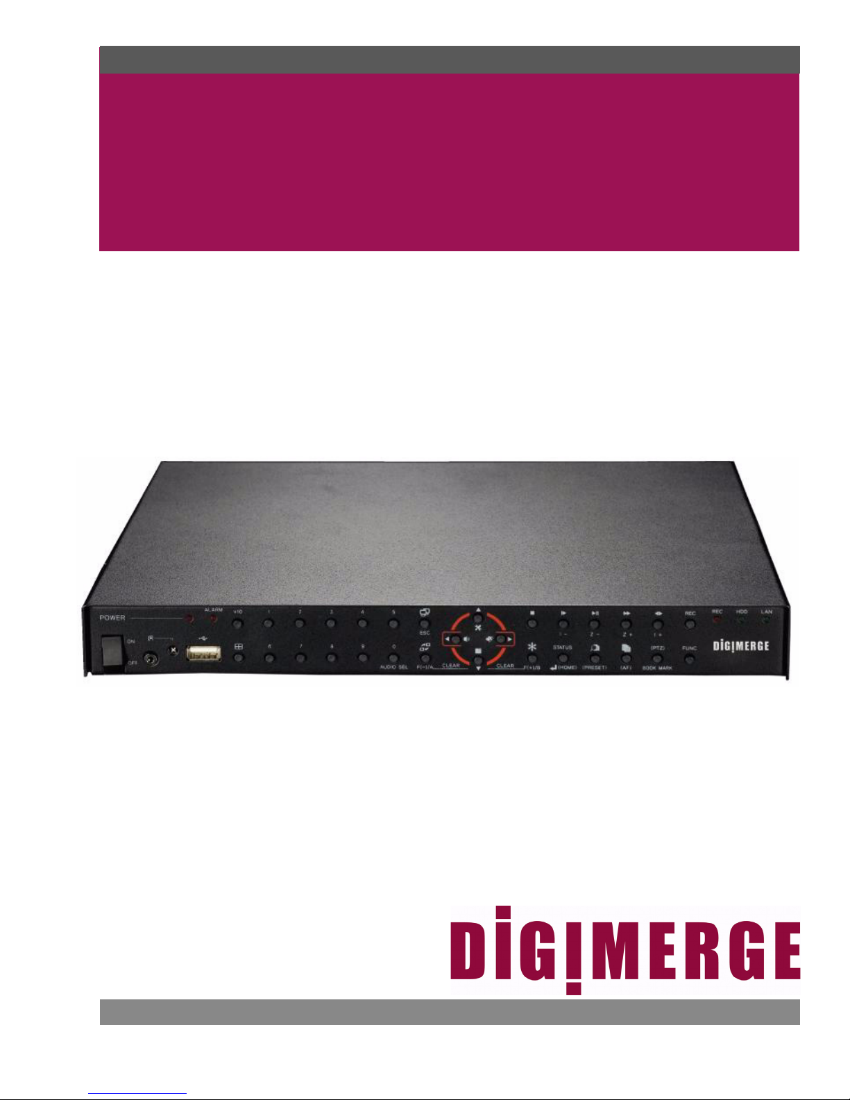
Thank you for purchasing the VB300 Blade H.264 Digital Video Recorder.
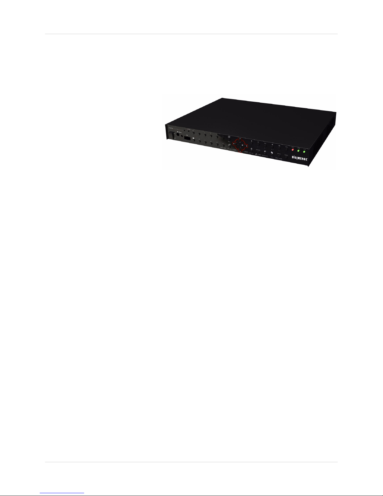
The Blade DVR features a slim, compact design that lets you conveniently attach it to the back
of most LCD monitors. The Blade’s slender housing still delivers professional-grade
performace with H.264 compression, Quadplex functionality, Smart Video detection, and full
POS/ATM* and Web browser support.
To learn more about the Blade DVR, and to learn about our complete range of accessory
products, please visit our website at:
www.digimerge.com
CAUTION
RISK OF ELECTRIC SHOCK
DO NOT OPEN
CAUTION: TO REDUCE THE RICK OF ELECTRIC SHOCK DO
NOT REMOVE COVER. NO USER SERVICABLE PARTS INSIDE.
REFER SERVICING TO QUALIFIED SERVICE PERSONNEL.
The lightning flash with arrowhead symbol, within an equilateral
triangle, is intended to alert the user to the presence of uninsulated
"dangerous voltage" within the products ' enclosure that may be of
sufficient magnitude to constitute a risk of electric shock
The exclamation point within an equilateral triangle is intended to
alert the user to the presence of important operating and
maintenance (servicing) instructions in the literature accompanying
the appliance.
WARNING: TO PREVENT FIRE OR SHOCK HAZARD, DO NOT
EXPOSE THIS UNIT TO RAIN OR MOISTURE.
CAUTION: TO PREVENT ELECTRIC SHOCK, MATCH WIDE
BLADE OF THE PLUG TO THE WIDE SLOT AND FULLY
INSERT.
*Additional equipment required—approved products only.
DivX Player™, Quicktime Player™, Windows Media Player™, and VLC™ are registered trademarks of their
respective companies, registered in the United States and other countries.
i
Page 4
Important Safeguards
In addition to the careful attention devoted to quality standards in the manufacture process of your video
product, safety is a major factor in the design of every instrument. However, safety is your responsibility too.
This sheet lists important information that will help to assure your enjoyment and proper use of the video
product and accessory equipment. Please read them carefully before operating and using your video product.
Installation
1. Read and Follow Instructions - All the safety and
operating instructions should be read before the
video product is operated. Follow all operating
instructions.
2. Retain Instructions - The safety and operating
instructions should be retained for future reference.
3. Heed Warnings - Comply with all warnings on the
video product and in the operating instructions.
4. Polarization - Do not defeat the safety purpose of
the polarized or grounding-type plug.
A polarized plug has two blades with
one wider than the other.
A grounding type plug has two blades
and a third grounding prong.
The wide blade or the third prong are
provided for your safety.
If the provided plug does not fit into
your outlet, consult an electrician for
replacement of the obsolete outlet
5. .Power Sources - This video product should be
operated only from the type of power source
indicated on the marking label. If you are not sure of
the type of power supply to your location, consult
your video dealer or local power company. For video
products intended to operate from battery power, or
other sources, refer to the operating instructions.
6. Overloading - Do not overload wall outlets of
extension cords as this can result in the risk of fire
or electric shock. Overloaded AC outlets, extension
cords, frayed power cords, damaged or cracked wire
insulation, and broken plugs are dangerous. They
may result in a shock or fire hazard. Periodically
examine the cord, and if its appearance indicates
damage or deteriorated insulation, have it replaced
by your service technician.
7. Power-Cord Protection - Power supply cords should
be routed so that they are not likely to be walked on
or pinched by items placed upon or against them,
paying particular attention to cords at plugs,
convenience receptacles, and the point where they
exit from the video product.
8. Ventilation - Slots and openings in the case are
provided for ventilation to ensure reliable operation
of the video product and to protect it from
overheating. These openings must not be blocked
or covered. The openings should never be blocked
by placing the video equipment on a bed, sofa, rug,
or other similar surface. This video product should
never be placed near or over a radiator or heat
register. This video product should not be placed in
a built-in installation such as a bookcase or rack
unless proper ventilation is provided or the video
product manufacturer’s instructions have been
followed.
9. Attachments - Do not use attachments unless
recommended by the video product manufacturer as
they may cause a hazard.
10. Water and Moisture - Do not use this video product
near water. For example, near a bath tub, wash bowl,
kitchen sink or laundry tub, in a wet basement, near
a swimming pool and the like.
Caution: Maintain electrical safety. Powerline
operated equipment or accessories connected to
this unit should bear the UL listing mark of CSA
certification mark on the accessory itself and should
not be modified so as to defeat the safety features.
This will help avoid any potential hazard from
electrical shock or fire. If in doubt, contact qualified
service personnel.
11. Accessories - Do not place this video equipment
on an unstable cart, stand, tripod, or table. The video
equipment may fall, causing
serious damage to the video
product. Use this video product
only with a cart, stand, tripod,
bracket, or table recommended by
the manufacturer or sold with the
video product. Any mounting of the
product should follow the
manufacturer’s instructions and
use a mounting accessory recommended by the
manufacturer.
ii
Page 5

Service
Use
13. Servicing - Do not attempt to service this video
equipment yourself as opening or removing covers
may expose you to dangerous voltage or other
hazards. Refer all servicing to qualified service
personnel.
14. Conditions Requiring Service - Unplug this video
product from the wall outlet and refer servicing to
qualified service personnel under the following
conditions.
A. When the power supply cord or plug is
damaged.
B. If liquid has been spilled or objects have fallen
into the video product.
C. If the video product has been exposed to rain
or water.
D. If the video product does not operate normally
by following the operating instructions. Adjust
only those controls that are covered by the
operating instructions. Improper adjustment of
other controls may result in damage and will often
require extensive work by a qualified technician
to restore the video product to its normal
operation.
E. If the video product has been dropped or the
cabinet has been damaged.
F. When the video product exhibits a distinct
change in performance. This indicates a need for
service.
19. Cleaning - Unplug the video product from the wall
outlet before cleaning. Do not use liquid cleaners or
aerosol cleaners. Use a damp cloth for cleaning.
20. Product and Cart Combination - Video and cart
combination should be moved with care. Quick
stops, excessive force, and uneven surfaces may
cause the video product and car combination to
overturn.
21. Object and Liquid Entry - Never push objects for
any kind into this video product through openings as
they may touch dangerous voltage points or
“short-out” parts that could result in a fire or electric
shock. Never spill liquid of any kind on the video
product.
22. Lightning - For added protection for this video
product during a lightning storm, or when it is left
unattended and unused for long periods of time,
unplug it from the wall outlet and disconnect the
antenna or cable system. This will prevent damage
to the video product due to lightning and power line
surges.
15. Replacement Parts - When replacement parts are
required, have the service technician verify that the
replacements used have the same safety
characteristics as the original parts. Use of
replacements specified by the video product
manufacturer can prevent fire, electric shock or other
hazards.
16. Safety Check - Upon completion of any service or
repairs to this video product, ask the service
technician to perform safety checks recommended
by the manufacturer to determine that the video
product is in safe operating condition.
17. Wall or Ceiling Mounting - The cameras provided
with this system should be mounted to a wall or
ceiling only as instructed in this guide, using the
provided mounting brackets.
18. Heat - The product should be situated away from
heat sources such as radiators, heat registers,
stoves, or other products (including amplifiers) that
produce heat.
iii
Page 6

General Precautions
1. All warnings and instructions of this manual should be followed.
2. Remove the plug from the outlet before cleaning. Do not use liquid aerosol detergents. Use a
water dampened cloth for cleaning.
3. Do not use this unit in humid or wet places.
4. Keep enough space around the unit for ventilation. Slots and openings in the storage cabinet
should not be blocked.
5. During lightning storms, or when the unit is not used for a long time, disconnect the power
supply, antenna, and cables to protect the unit from electrical surge.
FCC CLASS B NOTICE
Note
This equipment has been tested and found to comply with the limits for a Class B digital device, pursuant to
Part 15 of the FCC Rules. These limits are designed to provide reasonable protection against harmful
interference in a residential installation. This equipment generates, uses, and can radiate radio frequency
energy and, if not in-stalled and used in accordance with the instruction, may cause harmful interference to
radio communications.
However, there is no guarantee that interference will not occur in a particular installation. If this equipment does
cause harmful interference to radio or television reception (which can be determined by turning the equipment
on and off), the user is encouraged to try to correct the interference by one or more of the following measures:
• Reorient or relocate the receiving antenna
• Increase the separation between the equipment and receiver
• Connect the equipment into an outlet on a circuit different from that to which the receiver is
connected
• Consult the dealer or an experienced radio or television technician for assistance
This equipment has been certified and found to comply with the limits regulated by FCC, EMC,
and LVD. Therefore, it is designated to provide reasonable protection against interference and will
not cause interference with other appliance usage.
However, it is imperative that the user follows this manuals guideline to avoid improper usage
which may result in damage to the unit, electrical shock and fire hazard injury
In order to improve the feature functions and quality of this product, the specifications are subject
to change without notice from time to time.
iv
www.digimerge.com
Page 7

Table of Contents
Features . . . . . . . . . . . . . . . . . . . . . . . . . . . . . . . . . . . . . . . . . . . . . . . . . . . . . . . . . . . . . 4
Getting Started . . . . . . . . . . . . . . . . . . . . . . . . . . . . . . . . . . . . . . . . . . . . . . . . . . . . . . . 5
Basic Setup . . . . . . . . . . . . . . . . . . . . . . . . . . . . . . . . . . . . . . . . . . . . . . . . . . . . . . . . . . 6
Mount the Blade DVR . . . . . . . . . . . . . . . . . . . . . . . . . . . . . . . . . . . . . . . . . . . . . . . . . . . . . . 6
Connect the Cameras . . . . . . . . . . . . . . . . . . . . . . . . . . . . . . . . . . . . . . . . . . . . . . . . . . . . . . 6
Connect a DVI monitor . . . . . . . . . . . . . . . . . . . . . . . . . . . . . . . . . . . . . . . . . . . . . . . . . . . . . 6
Connect the IR Extender . . . . . . . . . . . . . . . . . . . . . . . . . . . . . . . . . . . . . . . . . . . . . . . . . . . . 6
Front Panel . . . . . . . . . . . . . . . . . . . . . . . . . . . . . . . . . . . . . . . . . . . . . . . . . . . . . . . . . .7
Front Panel (cont’d.) . . . . . . . . . . . . . . . . . . . . . . . . . . . . . . . . . . . . . . . . . . . . . . . . . . . 8
Rear Panel . . . . . . . . . . . . . . . . . . . . . . . . . . . . . . . . . . . . . . . . . . . . . . . . . . . . . . . . . . .9
Remote Control . . . . . . . . . . . . . . . . . . . . . . . . . . . . . . . . . . . . . . . . . . . . . . . . . . . . . . 10
Mouse Control . . . . . . . . . . . . . . . . . . . . . . . . . . . . . . . . . . . . . . . . . . . . . . . . . . . . . . . 11
Menu Navigation Tips and Tricks . . . . . . . . . . . . . . . . . . . . . . . . . . . . . . . . . . . . . . . 11
Using the System . . . . . . . . . . . . . . . . . . . . . . . . . . . . . . . . . . . . . . . . . . . . . . . . . . . . 12
Starting the System . . . . . . . . . . . . . . . . . . . . . . . . . . . . . . . . . . . . . . . . . . . . . . . . . . . . . . . 12
Password . . . . . . . . . . . . . . . . . . . . . . . . . . . . . . . . . . . . . . . . . . . . . . . . . . . . . . . . . . . . . . 12
On-Screen Display . . . . . . . . . . . . . . . . . . . . . . . . . . . . . . . . . . . . . . . . . . . . . . . . . . . . . . . 13
Display Views . . . . . . . . . . . . . . . . . . . . . . . . . . . . . . . . . . . . . . . . . . . . . . . . . . . . . . . . . . . 14
Additional Display Functions . . . . . . . . . . . . . . . . . . . . . . . . . . . . . . . . . . . . . . . . . . . . . . . . 15
Auto Sequence . . . . . . . . . . . . . . . . . . . . . . . . . . . . . . . . . . . . . . . . . . . . . . . . . . . . . . . . . . . . . . 15
Freeze . . . . . . . . . . . . . . . . . . . . . . . . . . . . . . . . . . . . . . . . . . . . . . . . . . . . . . . . . . . . . . . . . . . . . 15
Picture-in-Picture . . . . . . . . . . . . . . . . . . . . . . . . . . . . . . . . . . . . . . . . . . . . . . . . . . . . . . . . . . . . . 16
Setting the Time . . . . . . . . . . . . . . . . . . . . . . . . . . . . . . . . . . . . . . . . . . . . . . . . . . . . . 17
Recording . . . . . . . . . . . . . . . . . . . . . . . . . . . . . . . . . . . . . . . . . . . . . . . . . . . . . . . . . . 18
Event Recording . . . . . . . . . . . . . . . . . . . . . . . . . . . . . . . . . . . . . . . . . . . . . . . . . . . . . . . . . 18
Recording Audio . . . . . . . . . . . . . . . . . . . . . . . . . . . . . . . . . . . . . . . . . . . . . . . . . . . . . . . . . 18
Playback . . . . . . . . . . . . . . . . . . . . . . . . . . . . . . . . . . . . . . . . . . . . . . . . . . . . . . . . . . . 19
Search . . . . . . . . . . . . . . . . . . . . . . . . . . . . . . . . . . . . . . . . . . . . . . . . . . . . . . . . . . . . .20
CALENDAR SEARCH . . . . . . . . . . . . . . . . . . . . . . . . . . . . . . . . . . . . . . . . . . . . . . . . . . . . . . . . . 20
SEARCH & COPY . . . . . . . . . . . . . . . . . . . . . . . . . . . . . . . . . . . . . . . . . . . . . . . . . . . . . . . . . . . . 21
TIME SEARCH . . . . . . . . . . . . . . . . . . . . . . . . . . . . . . . . . . . . . . . . . . . . . . . . . . . . . . . . . . . . . . 22
EVENT SEARCH . . . . . . . . . . . . . . . . . . . . . . . . . . . . . . . . . . . . . . . . . . . . . . . . . . . . . . . . . . . . . 22
BLOCK SEARCH . . . . . . . . . . . . . . . . . . . . . . . . . . . . . . . . . . . . . . . . . . . . . . . . . . . . . . . . . . . . 23
FILE SEARCH . . . . . . . . . . . . . . . . . . . . . . . . . . . . . . . . . . . . . . . . . . . . . . . . . . . . . . . . . . . . . . . 23
BOOKMARK SEARCH . . . . . . . . . . . . . . . . . . . . . . . . . . . . . . . . . . . . . . . . . . . . . . . . . . . . . . . . 24
TEXT SEARCH* . . . . . . . . . . . . . . . . . . . . . . . . . . . . . . . . . . . . . . . . . . . . . . . . . . . . . . . . . . . . . 25
LOG FILE . . . . . . . . . . . . . . . . . . . . . . . . . . . . . . . . . . . . . . . . . . . . . . . . . . . . . . . . . . . . . . . . . . 25
Using the Main Menu . . . . . . . . . . . . . . . . . . . . . . . . . . . . . . . . . . . . . . . . . . . . . . . . . 26
QUICK . . . . . . . . . . . . . . . . . . . . . . . . . . . . . . . . . . . . . . . . . . . . . . . . . . . . . . . . . . . . . . . . . 27
SCREEN . . . . . . . . . . . . . . . . . . . . . . . . . . . . . . . . . . . . . . . . . . . . . . . . . . . . . . . . . . . . . . . 28
AUTO SEQUENCE . . . . . . . . . . . . . . . . . . . . . . . . . . . . . . . . . . . . . . . . . . . . . . . . . . . . . . . . . . . 28
DISPLAY . . . . . . . . . . . . . . . . . . . . . . . . . . . . . . . . . . . . . . . . . . . . . . . . . . . . . . . . . . . . . . . . . . . 29
TITLE . . . . . . . . . . . . . . . . . . . . . . . . . . . . . . . . . . . . . . . . . . . . . . . . . . . . . . . . . . . . . . . . . . . . . . 30
MULTI SCREEN . . . . . . . . . . . . . . . . . . . . . . . . . . . . . . . . . . . . . . . . . . . . . . . . . . . . . . . . . . . . . 30
COVERT . . . . . . . . . . . . . . . . . . . . . . . . . . . . . . . . . . . . . . . . . . . . . . . . . . . . . . . . . . . . . . . . . . . 31
SPOT . . . . . . . . . . . . . . . . . . . . . . . . . . . . . . . . . . . . . . . . . . . . . . . . . . . . . . . . . . . . . . . . . . . . . . 32
CAMERA . . . . . . . . . . . . . . . . . . . . . . . . . . . . . . . . . . . . . . . . . . . . . . . . . . . . . . . . . . . . . . . . . . . 32
1
Page 8

RECORD . . . . . . . . . . . . . . . . . . . . . . . . . . . . . . . . . . . . . . . . . . . . . . . . . . . . . . . . . . . . . . 33
RECORD SETUP . . . . . . . . . . . . . . . . . . . . . . . . . . . . . . . . . . . . . . . . . . . . . . . . . . . . . . . . . . . . 33
RECORD PROGRAM . . . . . . . . . . . . . . . . . . . . . . . . . . . . . . . . . . . . . . . . . . . . . . . . . . . . . . . . . 33
PREVIEW QUALITY . . . . . . . . . . . . . . . . . . . . . . . . . . . . . . . . . . . . . . . . . . . . . . . . . . . . . . . . . . 35
AUDIO RECORD . . . . . . . . . . . . . . . . . . . . . . . . . . . . . . . . . . . . . . . . . . . . . . . . . . . . . . . . . . . . . 35
REPEAT RECORD . . . . . . . . . . . . . . . . . . . . . . . . . . . . . . . . . . . . . . . . . . . . . . . . . . . . . . . . . . . 36
HOLIDAY . . . . . . . . . . . . . . . . . . . . . . . . . . . . . . . . . . . . . . . . . . . . . . . . . . . . . . . . . . . . . . . . . . . 36
RECORD LIMIT . . . . . . . . . . . . . . . . . . . . . . . . . . . . . . . . . . . . . . . . . . . . . . . . . . . . . . . . . . . . . . 37
BACKUP MODE . . . . . . . . . . . . . . . . . . . . . . . . . . . . . . . . . . . . . . . . . . . . . . . . . . . . . . . . . . . . . 37
EVENT . . . . . . . . . . . . . . . . . . . . . . . . . . . . . . . . . . . . . . . . . . . . . . . . . . . . . . . . . . . . . . . . 39
MOTION DETECTION . . . . . . . . . . . . . . . . . . . . . . . . . . . . . . . . . . . . . . . . . . . . . . . . . . . . . . . . 39
EVENT SCREEN MODE . . . . . . . . . . . . . . . . . . . . . . . . . . . . . . . . . . . . . . . . . . . . . . . . . . . . . . . 40
EVENT CHECK . . . . . . . . . . . . . . . . . . . . . . . . . . . . . . . . . . . . . . . . . . . . . . . . . . . . . . . . . . . . . . 40
EVENT MESSAGE . . . . . . . . . . . . . . . . . . . . . . . . . . . . . . . . . . . . . . . . . . . . . . . . . . . . . . . . . . . 40
EVENT BUZZER . . . . . . . . . . . . . . . . . . . . . . . . . . . . . . . . . . . . . . . . . . . . . . . . . . . . . . . . . . . . . 40
SENSOR INPUT . . . . . . . . . . . . . . . . . . . . . . . . . . . . . . . . . . . . . . . . . . . . . . . . . . . . . . . . . . . . . 41
RELAY OUTPUT . . . . . . . . . . . . . . . . . . . . . . . . . . . . . . . . . . . . . . . . . . . . . . . . . . . . . . . . . . . . . 41
SYSTEM . . . . . . . . . . . . . . . . . . . . . . . . . . . . . . . . . . . . . . . . . . . . . . . . . . . . . . . . . . . . . . . 42
HDD . . . . . . . . . . . . . . . . . . . . . . . . . . . . . . . . . . . . . . . . . . . . . . . . . . . . . . . . . . . . . . . . . . . . . . . 42
CLOCK . . . . . . . . . . . . . . . . . . . . . . . . . . . . . . . . . . . . . . . . . . . . . . . . . . . . . . . . . . . . . . . . . . . . 43
VIDEO STANDARD . . . . . . . . . . . . . . . . . . . . . . . . . . . . . . . . . . . . . . . . . . . . . . . . . . . . . . . . . . . 44
LANGUAGE . . . . . . . . . . . . . . . . . . . . . . . . . . . . . . . . . . . . . . . . . . . . . . . . . . . . . . . . . . . . . . . . . 44
REMOTE CONTROL ID . . . . . . . . . . . . . . . . . . . . . . . . . . . . . . . . . . . . . . . . . . . . . . . . . . . . . . . 44
KEY ECHO . . . . . . . . . . . . . . . . . . . . . . . . . . . . . . . . . . . . . . . . . . . . . . . . . . . . . . . . . . . . . . . . . 44
ADVANCED SETUP . . . . . . . . . . . . . . . . . . . . . . . . . . . . . . . . . . . . . . . . . . . . . . . . . . . . . . . . . . 45
ADVANCED SETUP (cont’d.) . . . . . . . . . . . . . . . . . . . . . . . . . . . . . . . . . . . . . . . . . . . . . . . . . . . 46
FIRMWARE UPGRADE . . . . . . . . . . . . . . . . . . . . . . . . . . . . . . . . . . . . . . . . . . . . . . . . . . . . . . . 47
LINK . . . . . . . . . . . . . . . . . . . . . . . . . . . . . . . . . . . . . . . . . . . . . . . . . . . . . . . . . . . . . . . . . . 48
NETWORK . . . . . . . . . . . . . . . . . . . . . . . . . . . . . . . . . . . . . . . . . . . . . . . . . . . . . . . . . . . . . . . . . 48
RS485 . . . . . . . . . . . . . . . . . . . . . . . . . . . . . . . . . . . . . . . . . . . . . . . . . . . . . . . . . . . . . . . . . . . . . 49
PTZ . . . . . . . . . . . . . . . . . . . . . . . . . . . . . . . . . . . . . . . . . . . . . . . . . . . . . . . . . . . . . . . . . . . . . . . 49
E-MAIL . . . . . . . . . . . . . . . . . . . . . . . . . . . . . . . . . . . . . . . . . . . . . . . . . . . . . . . . . . . . . . . . . . . . . 50
DVR NAME . . . . . . . . . . . . . . . . . . . . . . . . . . . . . . . . . . . . . . . . . . . . . . . . . . . . . . . . . . . . . . . . . 51
DVR LOCATION . . . . . . . . . . . . . . . . . . . . . . . . . . . . . . . . . . . . . . . . . . . . . . . . . . . . . . . . . . . . . 51
BANDWIDTH . . . . . . . . . . . . . . . . . . . . . . . . . . . . . . . . . . . . . . . . . . . . . . . . . . . . . . . . . . . . . . . . 51
DYNAMIC DNS . . . . . . . . . . . . . . . . . . . . . . . . . . . . . . . . . . . . . . . . . . . . . . . . . . . . . . . . . . . . . . 52
COPY . . . . . . . . . . . . . . . . . . . . . . . . . . . . . . . . . . . . . . . . . . . . . . . . . . . . . . . . . . . . . . . . . 53
COPY . . . . . . . . . . . . . . . . . . . . . . . . . . . . . . . . . . . . . . . . . . . . . . . . . . . . . . . . . . . . . . . . . . . . . 53
COPY STATUS . . . . . . . . . . . . . . . . . . . . . . . . . . . . . . . . . . . . . . . . . . . . . . . . . . . . . . . . . . . . . . 54
MEDIA FORMAT . . . . . . . . . . . . . . . . . . . . . . . . . . . . . . . . . . . . . . . . . . . . . . . . . . . . . . . . . . . . . 54
STATUS . . . . . . . . . . . . . . . . . . . . . . . . . . . . . . . . . . . . . . . . . . . . . . . . . . . . . . . . . . . . . . . 55
DVR STATUS . . . . . . . . . . . . . . . . . . . . . . . . . . . . . . . . . . . . . . . . . . . . . . . . . . . . . . . . . . . . . . . 55
NETWORK STATUS . . . . . . . . . . . . . . . . . . . . . . . . . . . . . . . . . . . . . . . . . . . . . . . . . . . . . . . . . . 56
RECORDING BITRATE . . . . . . . . . . . . . . . . . . . . . . . . . . . . . . . . . . . . . . . . . . . . . . . . . . . . . . . 56
SAVE / EXIT . . . . . . . . . . . . . . . . . . . . . . . . . . . . . . . . . . . . . . . . . . . . . . . . . . . . . . . . . . . . 56
Appendix 1: System Specifications . . . . . . . . . . . . . . . . . . . . . . . . . . . . . . . . . . . . . 57
Appendix 2: DigiClient Software Requirements . . . . . . . . . . . . . . . . . . . . . . . . . . . 61
Appendix 3: Setting up Remote Viewing . . . . . . . . . . . . . . . . . . . . . . . . . . . . . . . . . 62
What do I need? . . . . . . . . . . . . . . . . . . . . . . . . . . . . . . . . . . . . . . . . . . . . . . . . . . . . . . . . . 62
Network Setup / Remote Access Overview . . . . . . . . . . . . . . . . . . . . . . . . . . . . . . . . . . . . 62
How do I find my IP and MAC addresses? . . . . . . . . . . . . . . . . . . . . . . . . . . . . . . . . . . . . . 63
2
Page 9

How do I enable port forwarding? . . . . . . . . . . . . . . . . . . . . . . . . . . . . . . . . . . . . . . . . . . . . 64
Appendix 4: Setting Up DDNS Service . . . . . . . . . . . . . . . . . . . . . . . . . . . . . . . . . . . 65
How do I enable DDNS on my system? . . . . . . . . . . . . . . . . . . . . . . . . . . . . . . . . . . . . . . . 67
Appendix 5: Connect PTZ Cameras . . . . . . . . . . . . . . . . . . . . . . . . . . . . . . . . . . . . . 68
Appendix 6: Connecting a Spot Monitor . . . . . . . . . . . . . . . . . . . . . . . . . . . . . . . . . 69
Appendix 7: Connecting Motion / Alarm Devices . . . . . . . . . . . . . . . . . . . . . . . . . . 70
Installing a Sensor . . . . . . . . . . . . . . . . . . . . . . . . . . . . . . . . . . . . . . . . . . . . . . . . . . . . . . . 70
Appendix 8: Full Connectivity Diagram . . . . . . . . . . . . . . . . . . . . . . . . . . . . . . . . . . 71
Appendix 9: Replacing the Hard Drive . . . . . . . . . . . . . . . . . . . . . . . . . . . . . . . . . . . 72
Removing the Hard Drive . . . . . . . . . . . . . . . . . . . . . . . . . . . . . . . . . . . . . . . . . . . . . . . . . . 72
Replacing the Hard Drive . . . . . . . . . . . . . . . . . . . . . . . . . . . . . . . . . . . . . . . . . . . . . . . . . . 73
Formatting the Hard Drive . . . . . . . . . . . . . . . . . . . . . . . . . . . . . . . . . . . . . . . . . . . . . . . . . . 74
Appendix 10: Using Listen-in Audio . . . . . . . . . . . . . . . . . . . . . . . . . . . . . . . . . . . . . 75
Appendix 11: File Viewer . . . . . . . . . . . . . . . . . . . . . . . . . . . . . . . . . . . . . . . . . . . . . . 76
Launching File Viewer . . . . . . . . . . . . . . . . . . . . . . . . . . . . . . . . . . . . . . . . . . . . . . . . . . . . . 77
Playing Video . . . . . . . . . . . . . . . . . . . . . . . . . . . . . . . . . . . . . . . . . . . . . . . . . . . . . . . . . . . 78
Converting Video Files to AVI . . . . . . . . . . . . . . . . . . . . . . . . . . . . . . . . . . . . . . . . . . . . . . . 78
Playing AVI Files . . . . . . . . . . . . . . . . . . . . . . . . . . . . . . . . . . . . . . . . . . . . . . . . . . . . . . . . . 79
Appendix 12: Using Disk Mirroring . . . . . . . . . . . . . . . . . . . . . . . . . . . . . . . . . . . . . . 80
Equal Capacity USB Hard Drive . . . . . . . . . . . . . . . . . . . . . . . . . . . . . . . . . . . . . . . . . . . . . 80
Larger Capacity USB Hard Drive . . . . . . . . . . . . . . . . . . . . . . . . . . . . . . . . . . . . . . . . . . . . 80
Disk Overwrite . . . . . . . . . . . . . . . . . . . . . . . . . . . . . . . . . . . . . . . . . . . . . . . . . . . . . . . . . . . . . . . 81
Troubleshooting . . . . . . . . . . . . . . . . . . . . . . . . . . . . . . . . . . . . . . . . . . . . . . . . . . . . . 82
3
Page 10
Features
• Micro form factor
• H.264 compression
• Record, playback, backup, and
network simultaneously
• Mulitple input methods: Remote
Control, Front Panel, external
keyboard (not included) and PS/
2 mouse (not included)
• Slim 2.4” internal hard drive
• Intelligent Search and Playback—playback only video recorded by motion detection
• Smart Video Detection—motion dection and video loss
• POS/ATM support*
• Easy backup: USB flash drive, USB external hard drive, external CD-RW/DVD-RW
• Composite Video or DVI output
• Spot Monitor out
• PTZ camera support
• Upgrade firmware through USB or network
• Web browser support
• AVI file conversion
†
*Additional equipment required—approved products only.
†Supports only DVD-R/RW media.
4
Page 11
Getting Started
E
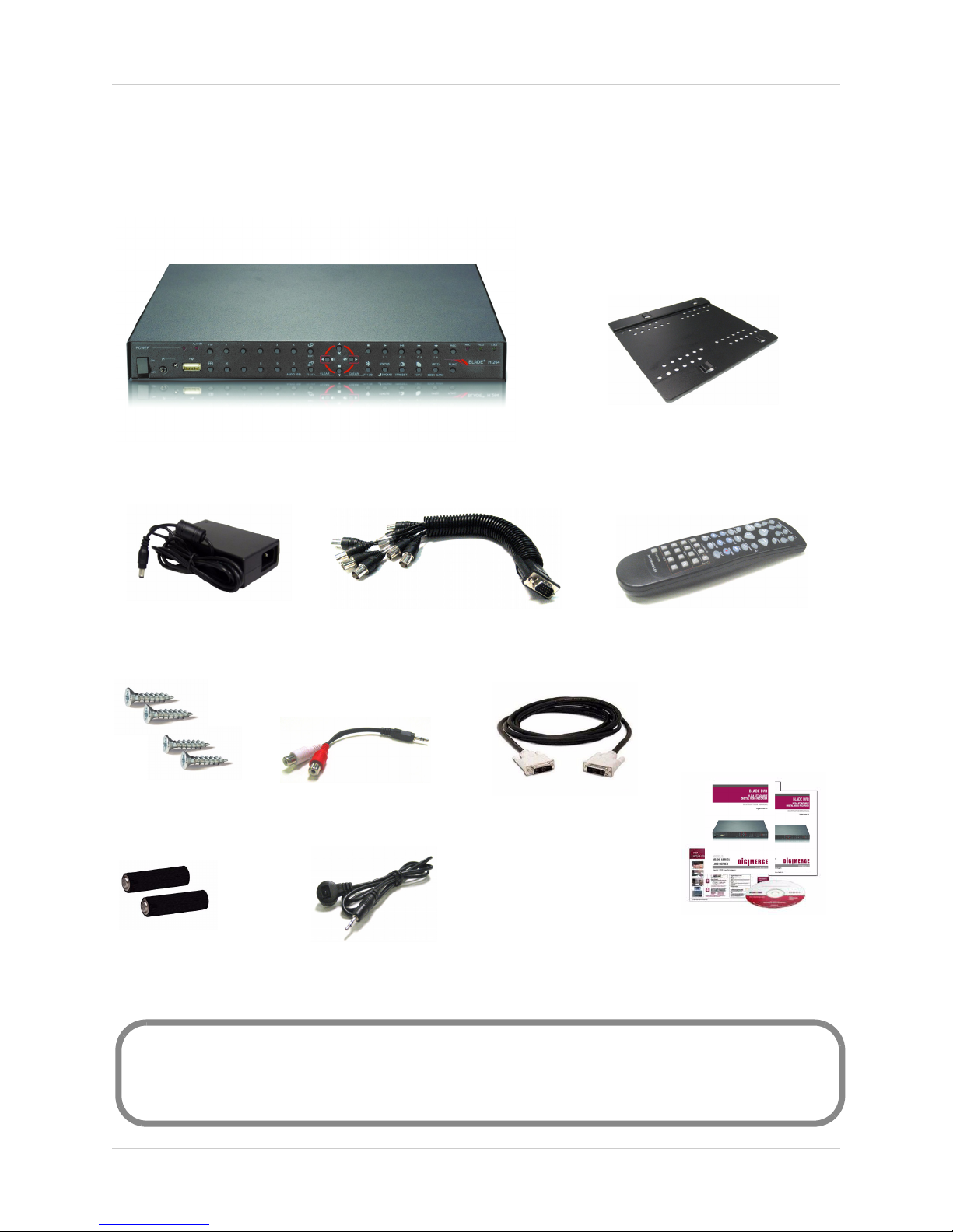
The system comes with the following components:
Getting Started
1 X BLADE DIGITAL VIDEO RECORDER
1 X POWER ADAPTOR
4 X SCREWS
2 X RCA "Y" ADAPTOR
1 X CAMERA OCTOPUS CABLE*
1 X MOUNTING PLATE
1 X REMOTE CONTROL
1 X DVI CABLE
2 X ’AA’ BATTERIES
*2 octopus cables included in 16-channel model
HARD DRIVE SIZE, NUMBER OF CHANNELS, AND CAMERA CONFIGURATION MAY VARY
BY MODEL. PLEASE REFER TO YOUR PACKAGE FOR SPECIFIC CONTENT DETAILS.
CHECK YOUR PACKAGE TO CONFIRM THAT YOU HAVE RECEIVED THE COMPLETE
SYSTEM, INCLUDING ALL COMPONENTS SHOWN ABOVE.
1 X IR EXTENDER
HARDWARE & SOFTWAR
MANUALS, QUICKSTART
GUIDE, & SOFTWARE CD
5
Page 12
Basic Setup
Basic Setup
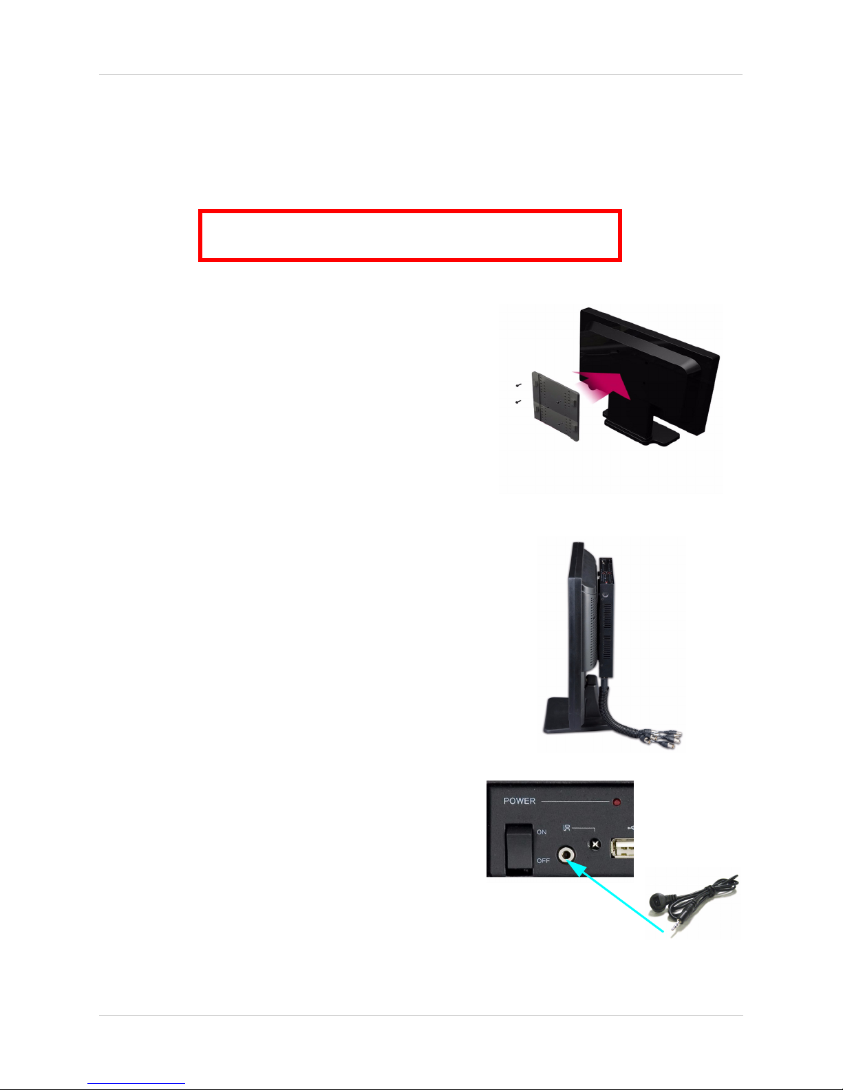
The Blade DVR is designed to mount securly to the back of LCD monitors with a VESA mount.
However, if desired, you can also leave the Blade DVR in a standard horizontal position.
ATTENTION: You can only mount the Blade DVR to an LCD
monitors with a VESA mount and an independent stand.
1. Mount the Blade DVR
a.Position the mounting plate on the back of the
LCD monitor (with a VESA mount) until mounting
holes on the back of the monitor are clearly
visible. Use the included screws to fasten the
mounting plate tightly to the monitor—make sure
the hooks are facing up.
b.Carefully place the Blade DVR (front panel facing
up) over the hooks and slide down into place. The
Blade DVR should be flush against the mounting
plate and sitting completely over all four hooks.
Figure 1.0 Attach the mounting plate to the monitor
2. Connect the Cameras
a.Connect up to eight BNC cameras to the ends of
the included octopus cable. Connect the VGA
termination of the octopus cable to the Camera In:
Ch. 1~8* port on the rear panel of the Blade DVR.
3. Connect a DVI monitor
a.Connect the included DVI cable from the DVI port
on the rear panel of the Blade DVR to the DVI port
on the back of your LCD monitor.
Note: Use the included DVI-to-VGA adaptor to
connect to a VGA monitor.
4. Connect the IR Extender
a.Connect the IR extender to the port on the front
panel of the DVR. Position the IR extender near
the front of your monitor, or where it will receive a
clear signal from the remote control.
Figure 1.1 Mount the Blade DVR to the monitor
Figure 1.2 Connect the IR extender
*16-channel model includes two octopus cables to connect up to 16 cameras.
6
Page 13
Front Panel
Front Panel
12
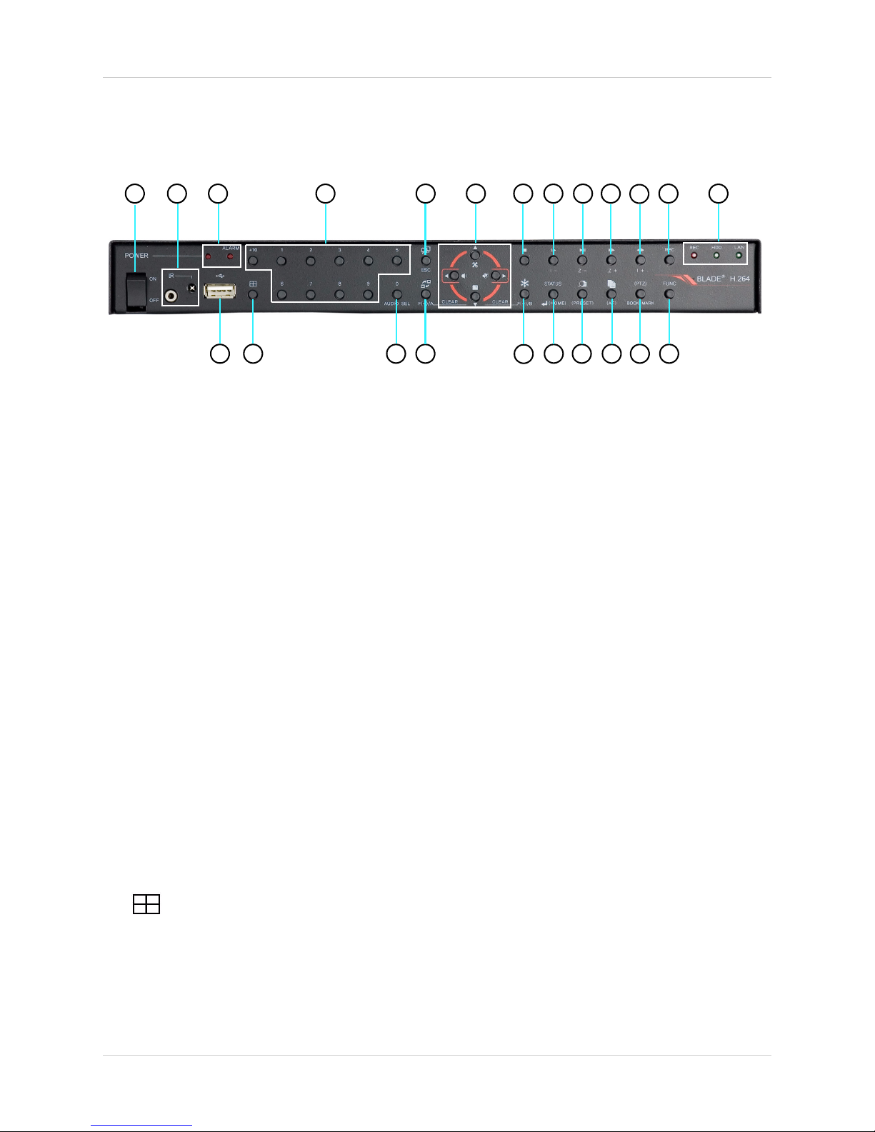
1. Power Button: Press to turn the Blade DVR ON/OFF
3
14
15 16 17 18 19 20 21 22 23
4
5
6
†
7
89
10
11
12 13
2. Mini-Jack (2.5mm): Connect an IR module extension cable.
3. LEDs: System power and Alarm LED indicators.
4. Channel Buttons: Press to view channels 1~9; press +10 then 0~6 to select channels 10~16*.
5. Spot Monitor Out/ESC: Press to view the Spot Monitor; In system menus, returns to previous menu.
6. Navigation Buttons:
S: Navigate Up; open System Menu
T: Navigate Down; open Picture-in-Picture (PIP)
W: Navigate Left; open Alarm
X: Navigate Right; open Zoom
Note: You can use the Navigation
Buttons to control movement of
connected PTZ cameras (not
included).
7. Stop: Press to stop playback.
8. Play: Press to start playback.
9. /: Press to pause playback; press again to resume playback.
10. FF: Press to increase playback speed: 1X, 2X, 4X, 16X, 32X, 64X, 128X.
11. Playback Direction: Press to switch between Reverse and Forward playback.
12. Record: Press to commence Recording.
13. LEDs: Record, HDD, and LAN LED indicators.
14. USB 2.0 Port: Connect two external USB hard drives or external CD-RW/DVD-RW drives for system
backup; connect USB flash drive to install firmware updates.
15. : Press to switch display modes: Single, Quad, 6, 7, 9, 10, 13, and 16-split screen.
16. Audio: Select audio channels.
*Channels 9~16 only available on 16-channel models.
†If you have passwords enabled on the system, the system will prompt you for your password
prior to shut-down.
7
Page 14
Front Panel (cont’d.)
Front Panel (cont’d.)
12
3
14 15 16 17 18 19 20 21 22 23
4
5
6
7
9
8
10
11
12
13
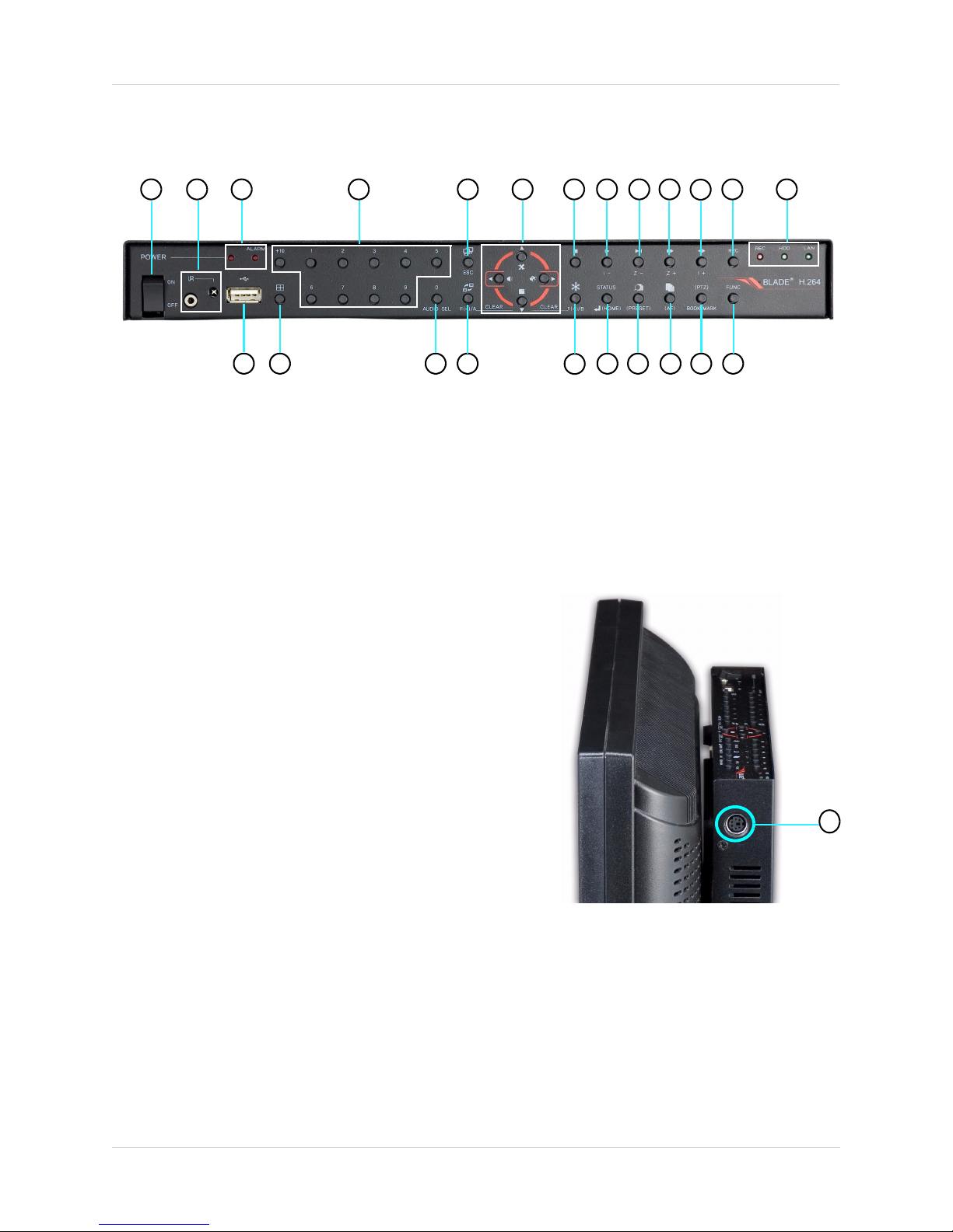
17. SEQ: Start/stop Auto-Sequence mode; increases, decrease, or changes values of selected menu
options.
18. Freeze: Press to start Freeze mode; press to focus control of PTZ; increases, decrease, or changes
values of selected menu options.
19. Enter: Press to select menu options; opens the Settings menu.
20. Preset: Press to open the Copy menu.
21. Menu: Press to open the System Menu; enables Auto Focus
22. Bookmark (PTZ): Press to add a bookmark while video is
paused during playback; open PTZ controller
23. Func: N/A
24. PS/2 Port: Connect a PS/2 mouse (optional).
8
24
Page 15
Rear Panel
Rear Panel
12
3
4
5
6
7
8
9
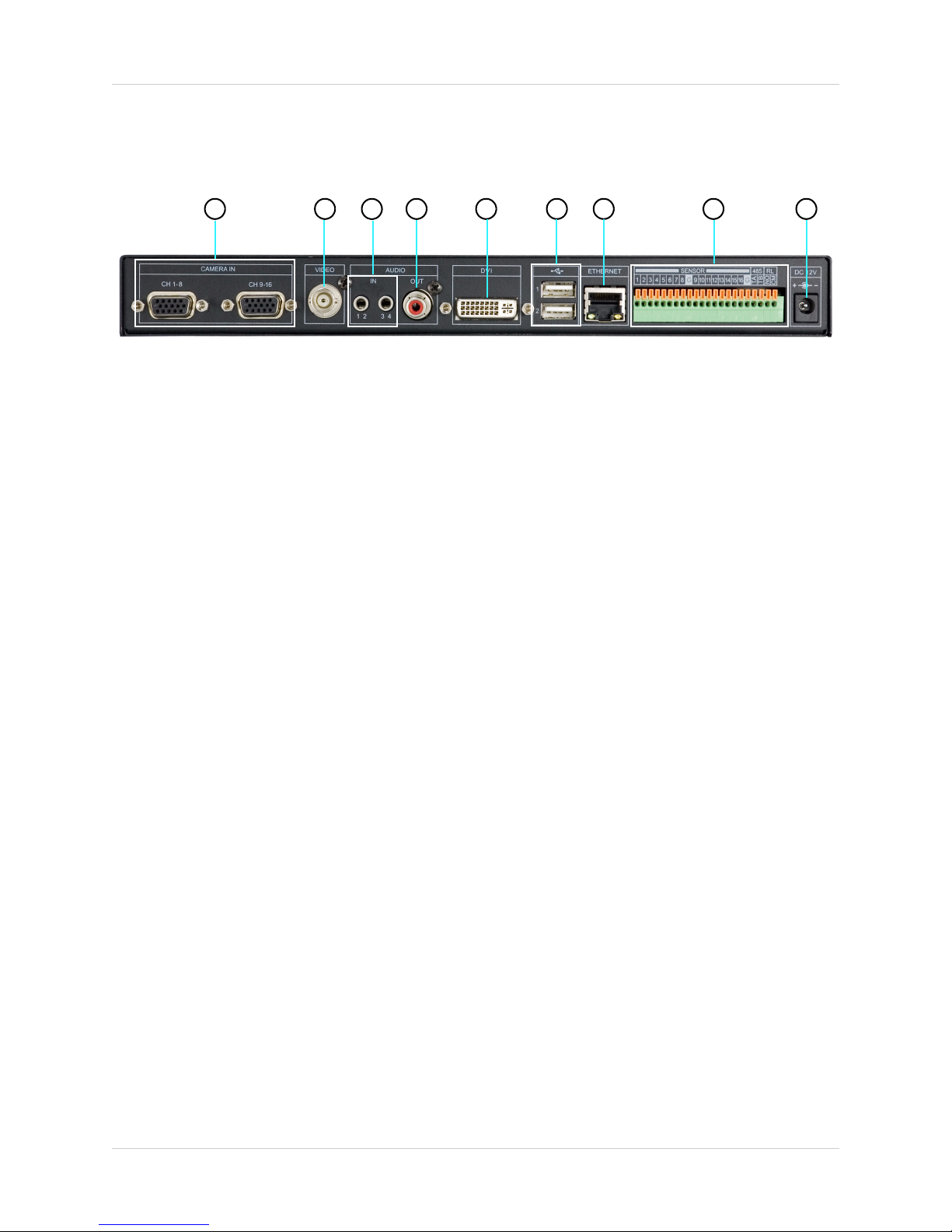
1. Camera In: Camera input ports for Camera Octopus Cables*.
2. Video: BNC port for a Spot Monitor.
3. Audio In: Two 3.5" RCA jacks for audio input (Y-cables included); the left port is for audio channels 1
and 2, the right port for audio channels 3 and 4.
4. Audio Out: RCA port for audio output (mono).
5. DVI: DVI output for connecting to a DVI monitor: use a DVI-to-VGA adaptor to connect to a VGA
monitor.
6. USB 2.0 Ports (x2): Connect external USB hard drives or external CD-RW/DVD-RW drives for system
backup; connect USB flash drive for to install firmware updates.
7. Ethernet: Networking port for a 10/100 Base-T RJ-45 network cable.
8. Alarm/Sensor/RS485: Connection block for alarms and sensor; connection for an RS485 PTZ
camera
9. DC 12V: Port for 12V DC 5A power adaptor cable (included).
*Channel port 9-16 only available on 16-channel models.
9
Page 16
Remote Control
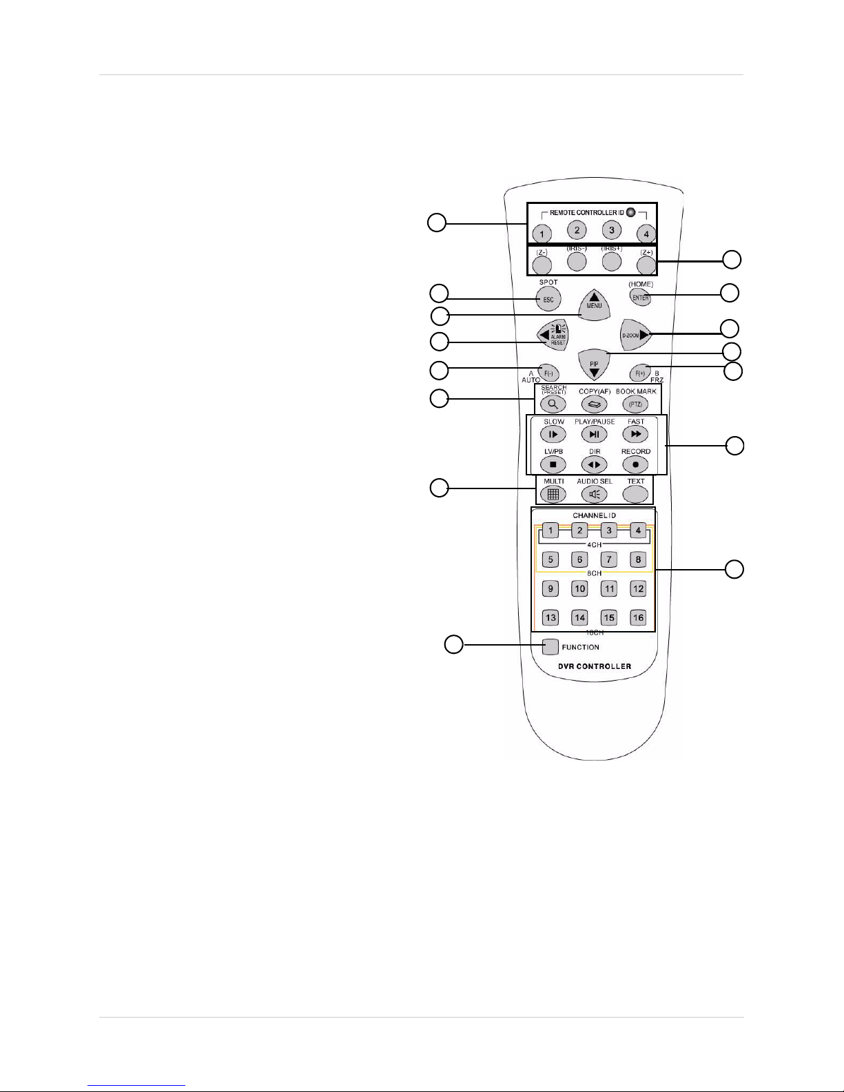
Remote Control
1. REMOTE CONTROL ID: Press buttons 1~4 to
match Remote Control ID entered in the System
Menu.
2. IRIS-/+, Z -/+:
• IRIS -/+: Press to open/close of a PTZ camera*;
press for Frame-by-Frame (field by field)
playback
• Z -/+: Zoom in/out using PTZ camera*
3. ESC/SPOT: Press to return to the previous menu;
press to open/close Spot mode.
4. ENTER/(HOME): Press to select a menu option;
press to go home in the PTZ Menu.
S/MENU: Move cursor up when navigating
5.
menus; press to open the System Menu.
6.
X/D-ZOOM: Mode cursor right when navigating
menus; control zoom in/out.
7. W/ALARM RESET: Move cursor left when
navigating menus; release the Event Signal.
8. T/PIP: Move cursor down when navigatign
menus; enter Picture-in-Picture mode.
9. A AUTO/F-: Press to start Auto Sequence mode;
press to decrease value of selected menu option;
focus control of PTZ camera*
10. B FRZ/F+: Press to open/close Freeze Mode;
press to increase value of selected menu option;
focus control of PTZ camera*
11. SEARCH/COPY/BOOKMARK:
• SEARCH (PRESET): Press to open the Search
Menu; enter the preset while in PTZ mode.
• COPY (AF): Press to open the Copy Menu; enable
Auto-Focus while in PTZ mode.
• BOOKMARK / (PTZ): Press to set Bookmark/
press to open PTZ mode (PTZ camera must be
connected).
12. Playback Controls:
• SLOW: Press to slow-down playback speed.
• PLAY/PAUSE: Press to begin playback; press
again to pause;
• FAST: Press to increase playback speed.
• LV/PB: Convert the screen into real display mode
during playback
• DIR: press to change the direction of playback.
• RECORD: Press to start/stop recording.
1
3
5
7
9
11
13
15
13. MULTI, AUDIO SEL, TEXT:
• MULTI: Change between display modes
• AUDIO SELECT: Change audio channels
• TEXT: Use when the DVR is connected to a P.O.S.
system
14. CHANNEL ID: Press to view full screen view of
individual channels (4CH, 8CH, 16CH).
15. FUNCTION: N/A
2
4
6
8
10
12
14
10
*PTZ cameras are not included with this system
Page 17
Mouse Control
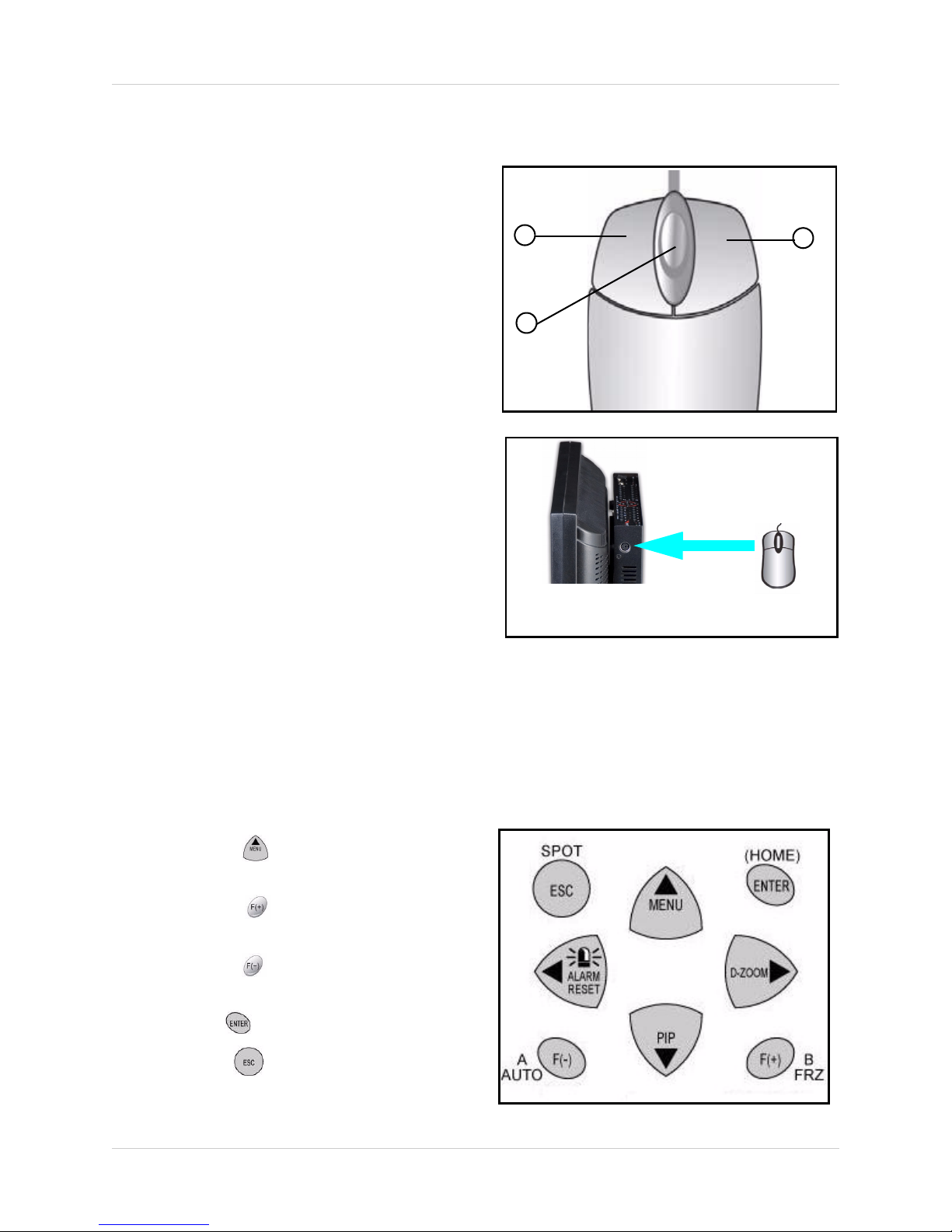
Control scheme for a PS/2 mouse
(optional).
1. Left-Button: While in a split-screen display
mode. double click an individual channel to
view it in full-screen; double click again to
return to the split-screen display mode.
While navigating menus, click to slect a
menu option; double-click to open the next
menu.
2. Right-Button: Right-click anywhere on the
screen to open the System Menu;
double-click anywhere on the screen to
return to the previous menu.
3. Scroll-Wheel: Scroll the wheel or down to
increase/decrease the value of a selected
menu option.
Mouse Control
1
3
2
MONITOR
w/ DVR
Connect the PS/2 mouse to the port on the side panel
PS/2 MOUSE
Menu Navigation Tips and Tricks
Use the navigation buttons on the remote control as the primary input for the user interface. The
following buttons are frequently used
when navigating the menus:
• Press the button to open the
system Main Menu.
• Press the button to increase
values for selected menu options.
• Press the button to decrease
values for selected menu options.
• Press the button to enter/confirm.
• Press the button to return to a
previous menu / close windows / quit
menus.
11
Page 18
Using the System
Using the System
Note: Make sure all cameras and cables are properly connected prior to powering on the
system.
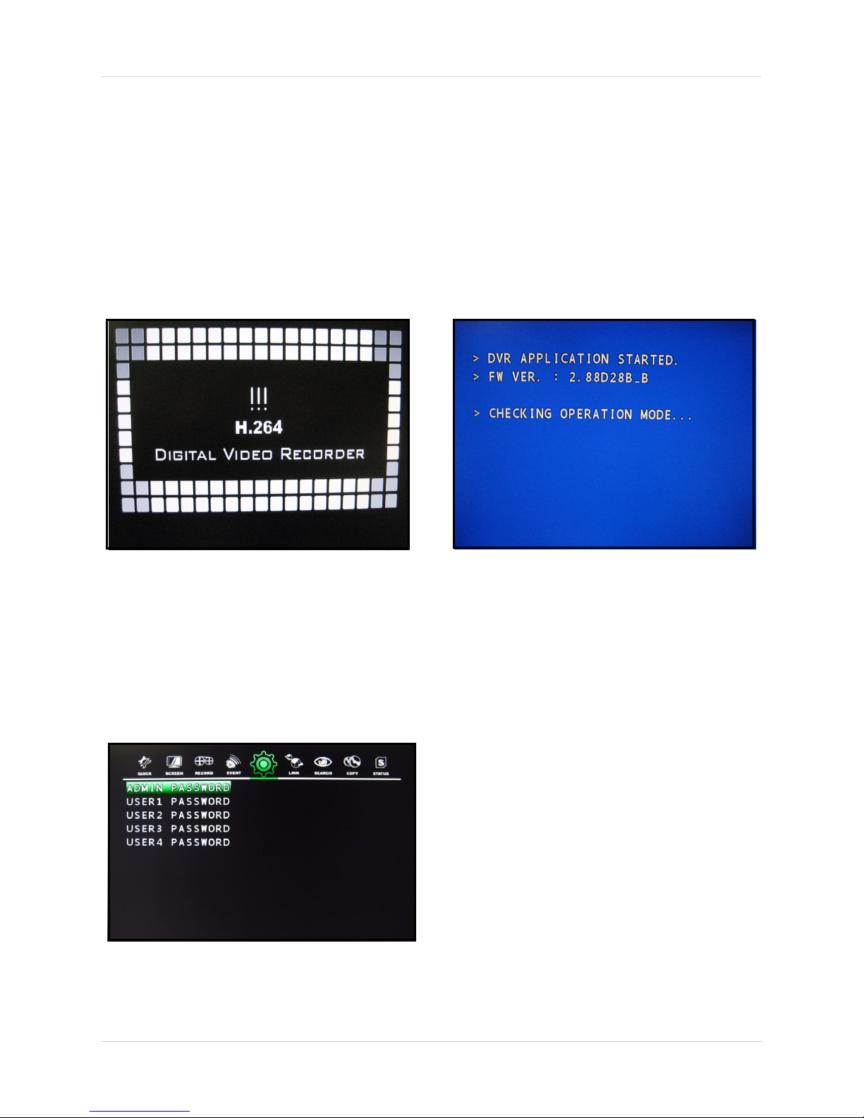
Starting the System
Press the POWER button on the front panel to turn the system ON/OFF.
At startup, the system performs a basic system check and runs an initial loading sequence.* After
a few moments, the system loads a live display view.
Figure 2.0 Initial startup screens
Password
You do not have to enter a password upon initial startup. However, for security measures, you
should change your ADMIN and user passwords after first purchasing the system.
“ADVANCED SETUP” on page 50.
Figure 2.1 Passwords
See
*The system may perform "Time Trimming" at startup. This is a normal function that the system uses to correct its internal clock.
12
Page 19
On-Screen Display
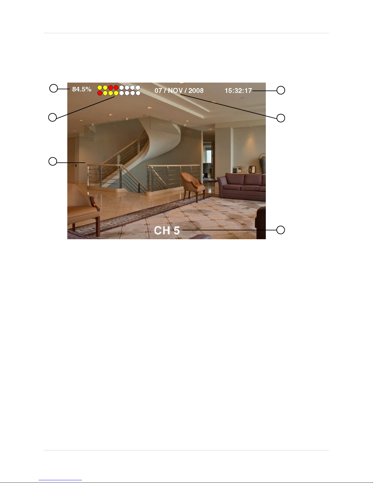
The system shows the following for all of the display views:
Using the System
1
2
3
Figure 3.0 Main system display
4
5
6
1. HDD percentage: The percentage of free space remaining on the hard disk. Other system functions,
such a s Freeze, Auto-Sequence, and Playback will display in this top-left corner.
2. Camera channels:
• Yellow: Continuous recording for connected cameras
• White: Disconnected/inactive camera
• Red: Event recording: motion, alarm
3. Channel display:(single channel or multi-channel)
4. Date-Stamp: (yyyy/mm/dd; 24HR clock)
5. Channel name: By default, the indivdual channel number appears at the bottom of the frame. You can
customize the channel with a unique name for each channel.
See “TITLE” on page 33.
13
Page 20
Using the System
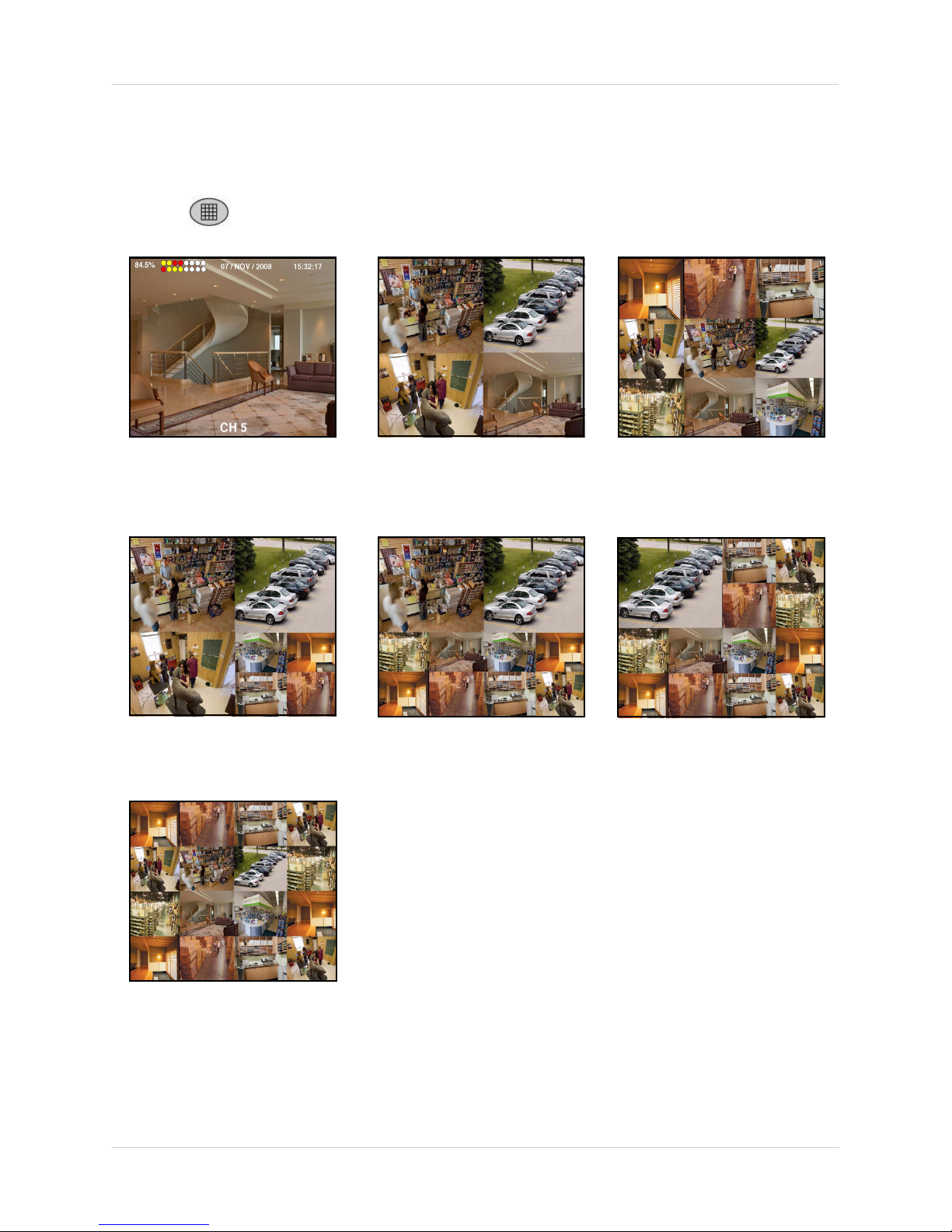
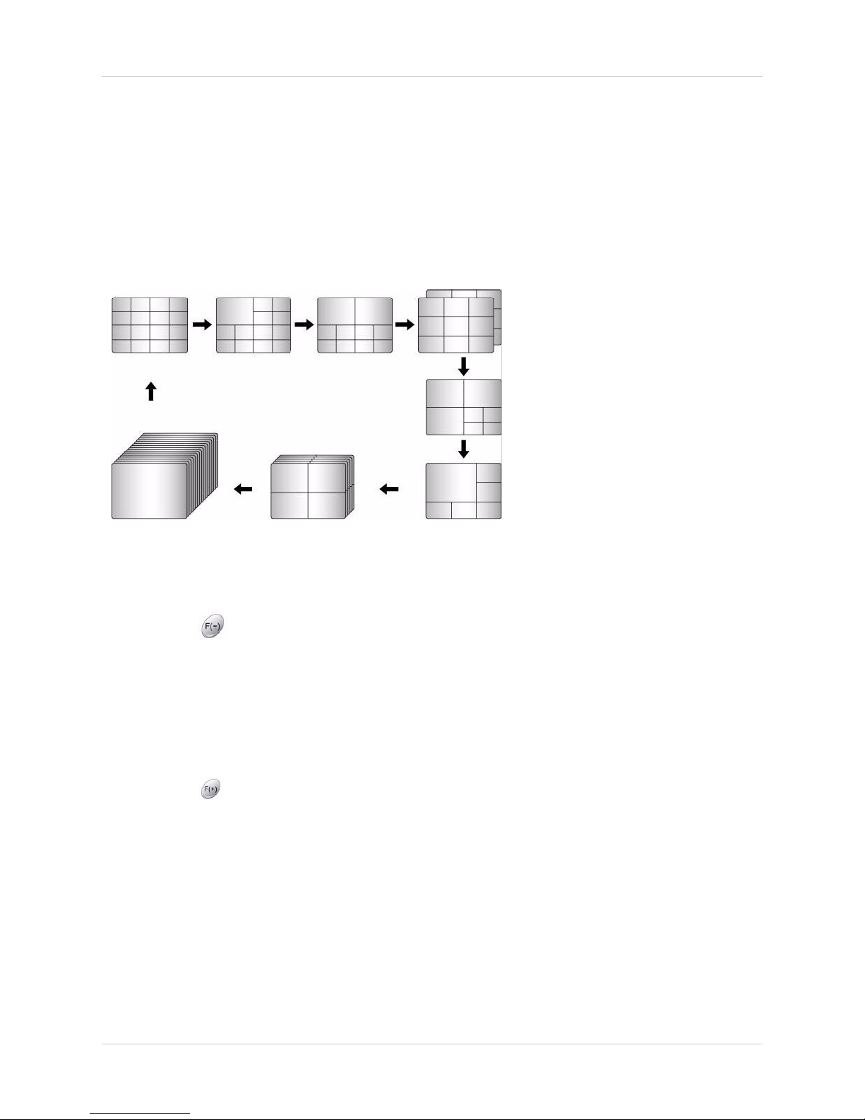
Display Views
You can view connected cameras on the system in various configurations.
Press the button on the remote control to change between display views.
Single channel (full-screen)
7-channel*
Quad *
10-channel*
9-channel*
16-channel (grid)
*Customize the layout for the five
multi-screen display views from Main
Menu>Screen>Multi Screen. See “MULTI
SCREEN” on page 33.
16-channel (grid)
Figure 3.1 Multi-screen displays
14
Page 21
Using the System
Additional Display Functions
The system includes Auto Sequence, Freeze, and Picture-in-Picture to help maximize your
security needs.
Auto Sequence
Auto Sequence allows you to view all channels in sequence. You customize what display modes
to include or exclude from Auto Sequence, including full-screen single channels and video loss
channels.
See “AUTO SEQUENCE” on page 31.
Figure 3.2 Auto-Sequence displays
To enable Auto Sequence:
1. Press the button on the remote control.
2. Press again to stop Auto-Sequence.
Freeze
You can freeze the display image in both live mode and during playback.
To freeze the display image:
1. Press the button on the remote control.
2. Press again to unfreeze.
15
Page 22
Using the System
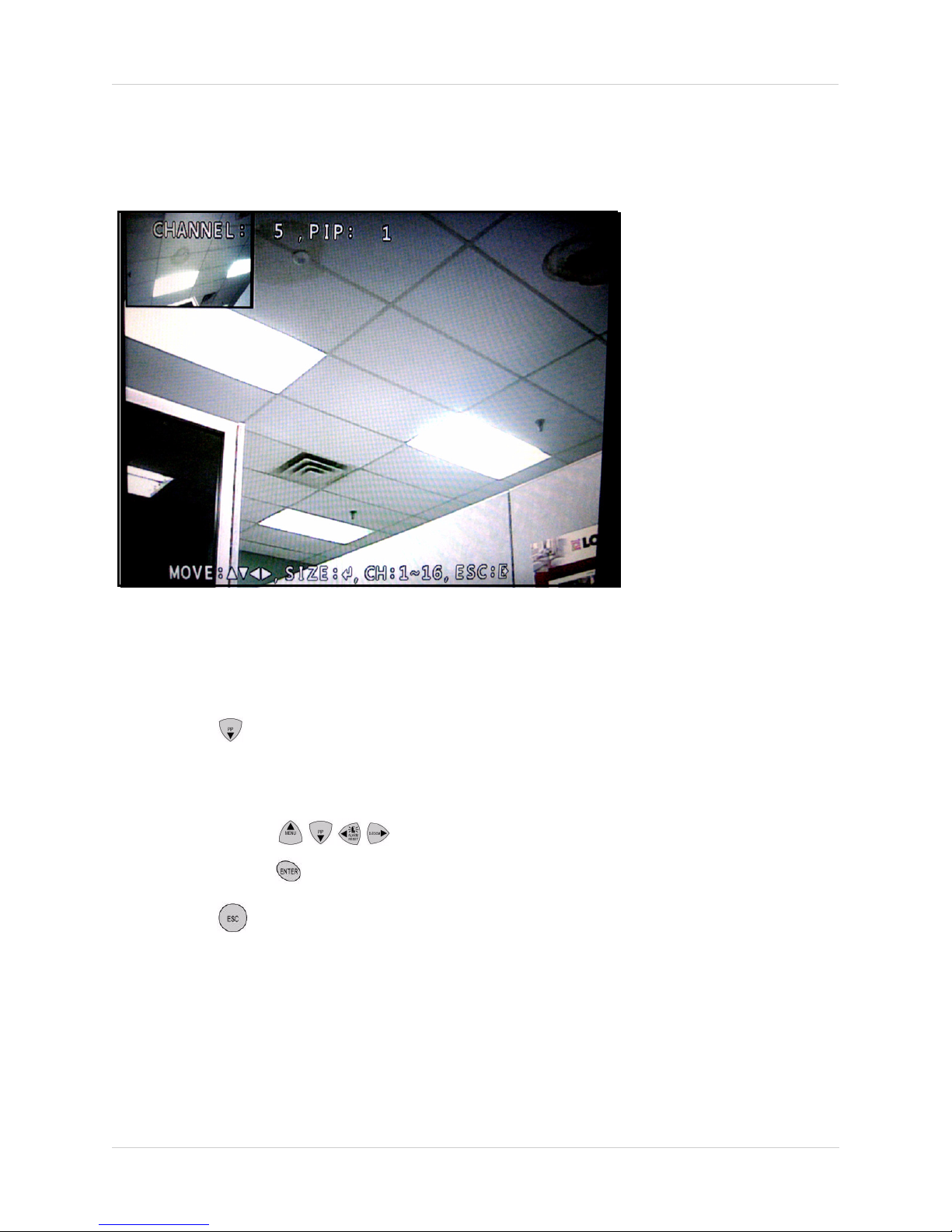
Picture-in-Picture
Monitor a second channel while in full-screen (single channel) mode using Picture-in-Picture
(PIP).
Figure 3.3 Picture-in-Picture display
To enable PIP:
1. Press channel buttons 1~16 on the remote control to view the channel in full screen.
2. Press the button on the remote control. The PIP window opens in the top-left corner.
3. Once in PIP mode, you have access to the following options:
• CHANNEL: Press channel buttons 1~16 to change the display channel in the PIP window
• MOVE: Press the
• SIZE: Press the
button to rezise the PIP window
buttons to reposition the PIP window anywhere on the screen.
4. Press the button to exit PIP mode.
16
Page 23
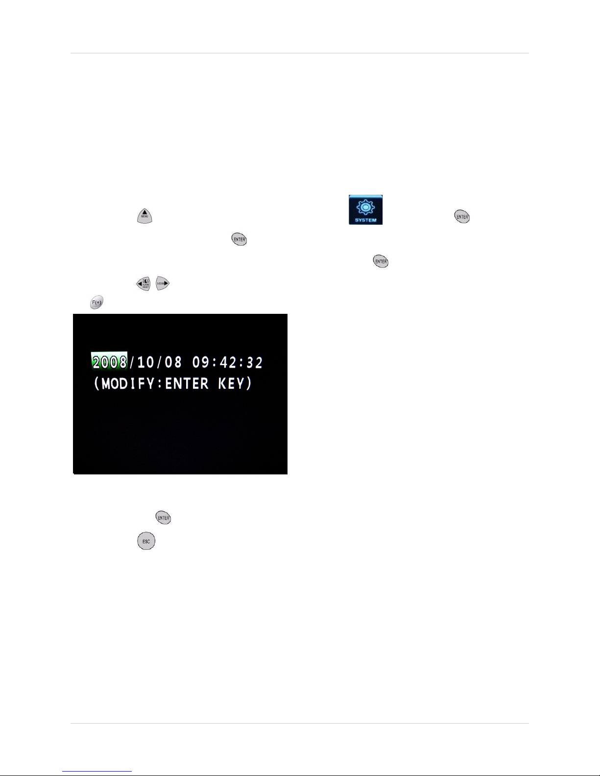
Setting the Time
Setting the Time
You should set the time on the system prior to doing any recording. You can set the time manually,
or set the time according to an Internet server (Internet connection and DDNS service required).
To set the date and time:
1. Press the button to open the system menu. Select and press the button.
2. Select CLOCK and press the button.
3. From the CLOCK menu, select DATE&TIME and press the button.
4. Press the buttons to select the year, month, day, hour, minute, and seconds. Press the
buttons to adjust the date and time.
Figure 4.0 Clock menu
5. Press the the button to save the date and time.
6. Press the button on the remote control until you see the Save/Exit screen. Select SAVE
ONLY or SAVE AND EXIT to save your settings.
You can also configure the time zone, daylight savings time, and have the system to use the
Internet to set the time (network connection required).
See “CLOCK” on page 47.
17
Page 24

Recording
Recording
By default, the system is set to immediately record video from connected cameras in Continuous
Record Mode. Also, the system is set to record based on a certain Recording Schedule and
Record Program. The system uses ten Record Programs that you can customize to best fit your
needs.
Event Recording
The system includes three modes of event recording:
See “RECORD PROGRAM” on page 36.
• Motion: The system records when motion is detected by the affected camera.
• Alarm: The system records when an alarm or sensor is triggered.
• Video Loss: The system records when a camera is disconnected or suffers video loss. The
system employs a pre-record function to capture video seconds before the video loss occured.
You can customize the recording parameters (video quality, frames-per-second) of Event
Recording in the Record menu.
Event Recording is also useful in Search Mode, as you can filter recorded video data according
to event types.
See “EVENT SEARCH” on page 23.
See “RECORD SETUP” on page 36.
Recording Audio
The system can record from two audio channels (four audio channels on the 16-channel model).
You must have audio enabled cameras or microphones connected to the system in order to use
this function.
See “AUDIO RECORD” on page 38.
18
Page 25
Playback
View recorded video on the system through playback mode.
Playback
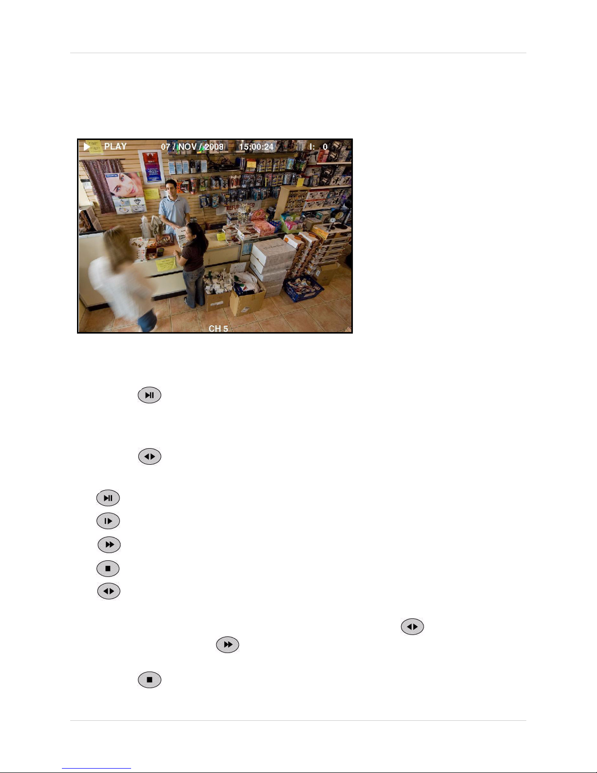
Figure 5.0 Playback display view
To begin playback:
1. Press the button on the remote control. The system will play the last 10 minutes of the
most recently recorded video.
OR
1. Press the to begin reverse playback.
2. Press the following buttons on the remote control to use playback functions:
• : Press to pause playback; press again to resume playback
• : View playback in slow motion (1/2, 1/4, 1/8, 1/16, 1/32, 1/64, 1/128)
• : Press to increase playback speed (2X, 4X, 8X, 16X, 32X, 64X, 128X).
• : Press to exit Playback mode and return to Live mode
• : From Live mode, press to begin reverse playback; during foward playback, press to
begin reverse playback
Note: To rewind, or reverse video during forward playback, press the button to begin reverse
playback, then press the button to increase playback speed.
3. Press the button to exit Playback mode.
19
Page 26
Search
Search
Search for recorded video data on the system according to the following:
• Calendar Search
• Search & Copy
• Time Search
• Event Search
• Block Search
• Press the button on the remote control to quickly open the Search menu.
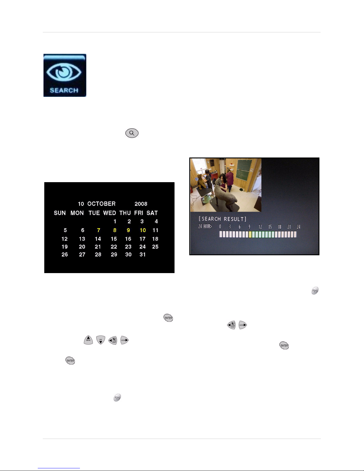
CALENDAR SEARCH
Search for recorded video according to date.
• File Search
• Bookmark Search
• Text Search
• Log File
Figure 6.0 Calendar search screen
To search by calendar date:
1. From the SEARCH menu, select
CALENDAR SEARCH and press the
button.
2. Press the buttons to
select a date on the calendar and press
the
button—only dates in yellow
contain recorded data. The SEARCH
RESULT screen opens.
Note: To change the month, select the
month and press the
buttons; to change
Figure 6.1 Search Result screen
the year, select the year and press the
buttons.
3. From the SEARCH RESULT screen,
press the
buttons to select an hour
block from the 24 HOUR bar at the bottom
of the screen and press the
After a brief pause, the video begins
playing.
Note: Green blocks contain video data;
white blocks do not contain video data. If
you attempt to play a white hour block, the
system will playback the most recently
recorded data.
button.
20
Page 27
Search
4. During playback, you have access to the
following options:
• Press the Playback Buttons on the
remote control to pause, fast forward, or
rewind video. See “The system can record
from two audio channels (four audio
channels on the 16-channel model). You
must have audio enabled cameras or
microphones connected to the system in
order to use this function. See “AUDIO
RECORD” on page 38.” on page 18.
• Press the button to change display
views; press the CHANNEL ID buttons to
view single channels in full screen
• Press the button and then press the
button to add a bookmark. See
“BOOKMARK SEARCH” on page 25.
Note: These options are available during
playback in all Search modes. Please allow
for a brief pause when switching between
single channels or between multi-screen
display views.
5. Press the button to exit playback
mode (left-click or move the scroll wheel of
using a mouse).
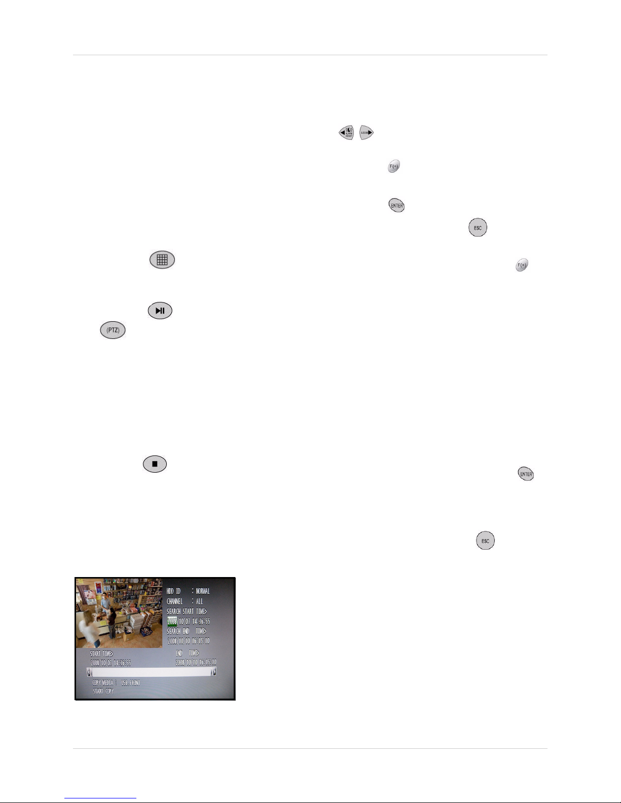
SEARCH & COPY
To use Search & Copy:
1. Under SEARCH START TIME, press the
buttons to select the year, month,
day, hour, minute, and second, and then
press the
buttons to change the
values.
2. Press the button to playback the
recorded video. Press the button to
return to the Search & Copy screen.
3. Under COPY MEDIA, press the the
buttons to select USB_FRONT,
USB_REAR1, or USB_REAR2
(INTERNAL CD-RW/DVD is not
applicable).
Note: The front panel USB port is typically
used for a USB flash drive, while the rear
panel USB ports are typically used for USB
external drives that remain connected to the
system during normal use.
4. If not already connected, connected a
USB drive to the system based on your
selection in step 3.
5. Select START COPY and press the
button.
6. Enter an 8-digit numeric password if you
want to protect your file. If you do not want
Search & Copy lets you search for recorded
video and instantly backup the data to a USB
external drive or USB flash drive (not included).
Figure 6.2 Search & Copy screen
to protect the file, press the
button to
begin copying. The system returns to the
live display screen, with copy progress
shown as a percentage in the top right
corner.
Note: Copy progress may take several
moments depening on the size of the file.
21
Page 28
Search
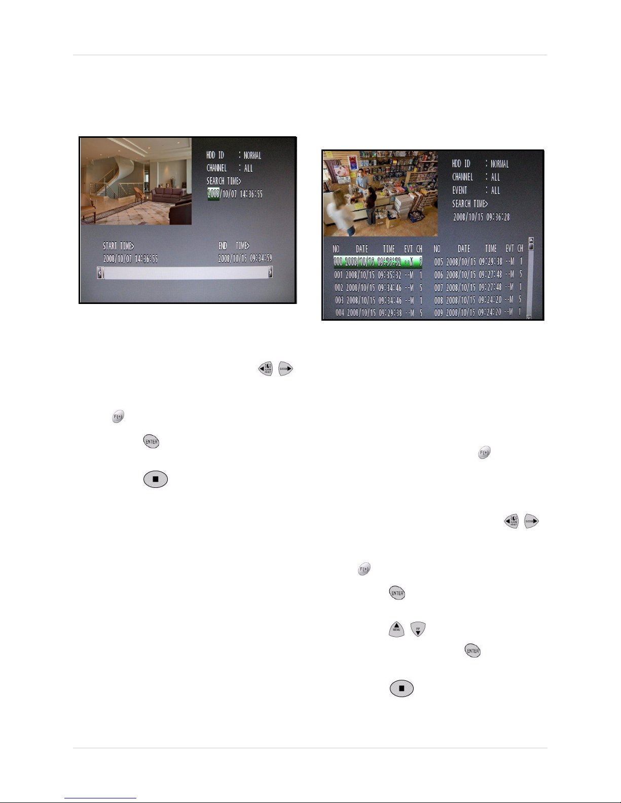
TIME SEARCH
Use Time Search to search for recorded video
date from a specific date and time.
Figure 6.3 Time Search screen
To use Time Search:
1. Under SEARCH TIME, press the
buttons to select the year, month, day,
hour, minute, and second, and then press
the
2. Press the button to playback the
recorded video.
3. Press the button to exit playback
mode (left-click or move the scroll wheel of
using a mouse).
buttons to change the values.
EVENT SEARCH
Use Event Search to quickly search for
recorded video according to motion, alarm, or
video loss events.
Figure 6.4 Event Search screen
To use Event Search:
1. Under HDD ID, select NORMAL, HDD 1,
or HDD 0.
Note: Normal is the default selection for the
single hard drive included with the system.
2. Under CHANNEL, press the buttons to
select channels 1~16 or ALL.
3. Under EVENT, select SENSOR, V-LOSS,
MOTION, or ALL.
4. Under SEARCH TIME, press the
buttons to select the year, month, day,
hour, minute, and second, and then press
22
the
buttons to change the values.
5. Press the button to view the events
for the selected date and time.
6. Press the buttons to select an
event and then press the button to
playback the video.
7. Press the button to exit playback
mode (left-click or move the scroll wheel of
using a mouse) and return to live mode.
Page 29

Search
BLOCK SEARCH
Use Block Search to search for recorded video
according to blocks on the hard disk.
Note: Block Search is recommended in
case of a failure when using other search
modes.
Figure 6.5 Block Search screen
To use Block Search:
1. Under HDD ID, select NORMAL, HDD 1,
or HDD 0.
Note: Normal is the default selection for the
single hard drive included with the system.
FILE SEARCH
Use File Search to search for video files saved
to an external USB drive or USB flash drive
(not included).
Figure 6.6 File Search screen
To use File Search:
1. If you already have an external USB drive
connected to the system, proceed to step
2. If not, connect a USB flash drive (that
contains saved video data) to the front
panel of the system.
2. From the SEARCH menu, select FILE
SEARCH and press the
button.
2. Under SEARCH TIME, press the
buttons to select the year, month, day,
hour, minute, and second, and then press
the
buttons to change the values.
3. Press the button to view the blocks for
the selected date and time.
4. Press the buttons to select a block
and then press the button to playback
the video.
5. Press the button to exit playback
mode (left-click or move the scroll wheel of
using a mouse) and return to live mode.
3. Under MEDIA, press the buttons to
select USB_FRONT, USB_REAR1, or
USB_REAR2 and press the
button. A
list of .dvr files appears on the screen.
4. Press the buttons to select a file
and press the button to begin
playback.
5. Press the button to exit playback
mode (left-click or move the scroll wheel of
using a mouse) and return to live mode.
23
Page 30

Search
BOOKMARK SEARCH
Use Bookmark Search to quickly search
recorded video according to set bookmarks.
Note: You must have set bookmarks while
in Playback mode in order to use Bookmark
Search.
Figure 6.7 Bookmark Search screen
To set bookmarks:
1. During playback, press the button.
2. Press the button to set the
bookmark. The bookmark is saved to the
system.
To use Bookmark Search:
1. From the SEARCH menu, select
BOOKMARK SEARCH and press the
button.
2. Under HDD ID, select NORMAL, HDD 1,
or HDD 0.
Note: Normal is the default selection for the
single hard drive included with the system.
3. Press the button to view all the
bookmarks on the system. Go to step 4.
OR
3. Press the buttons to select a specific
date and time. Pr
ess the buttons to
change the values and then press the
button to view bookmarks.
4. Press the buttons to select a
bookmark from the list and then press the
button to begin playback.
5. Press the button to exit playback
mode (left-click or move the scroll wheel of
using a mouse) and return to live mode.
3. Press the button again to resume
playback.
24
Page 31

Search
TEXT SEARCH*
Use the Text Search to find recorded data from
a P.O.S. system.
Figure 6.8 Text Search screen
To use Text Search:
1. From the SEARCH menu, select TEXT
SEARCH and press the
2. Under HDD ID, select NORMAL, HDD 1,
or HDD 0.
button.
LOG FILE
Use the Log File to see a list of the activities
and events on the system.
Note: You must connect a USB drive to the
system in order to view log files.
Figure 6.9 Log File screen
To view the Log File:
1. If not already connected, connect a USB
flash drive to the front panel of the system.
2. From the SEARCH menu, select LOG
FILE and press the
button.
Note: Normal is the default selection for the
single hard drive included with the system.
3. Press the button to view all the Text
marks on the system. Go to step 4.
OR
3. Press the buttons to select a specific
date and time. Pr
ess the buttons to
change the values and then press the
button to view bookmarks.
4. Press the buttons to select a Text
mark from the list and then press the
button to begin playback.
5. Press the button to exit playback
mode (left-click or move the scroll wheel of
using a mouse) and return to live mode.
*Compatible P.O.S. system required.
3. Press the button to view log for the
entire system.
OR
3. Under SEARCH FILE, press the
buttons to select a specific date and time.
Pr
ess the buttons to change the values
and then press the button to view the
log for that specific date.
4. Press the buttons to scroll down
the list of files.
5. To save the log file, press the the
button to return to SEARCH FILE. Select
SAVE LOG and press the
button. The
log file is saved to the connected USB
drive as
DvrLog.txt
25
Page 32

Using the Main Menu
Using the Main Menu
To open the Main Menu:
• Press the button on the remote control to open the Main Menu.
1
5
Figure 7.0 System Main Menu
2
6
3
7
4
8
9
10
1. QUICK: Opens up the Quick Setup menu.
2. SCREEN: Adjust display, camera title, multi-screen, covert, spot, and Camera.
3. RECORD: Adjust Record Setup, Program, Preview Quality, Audio Record, and Holiday.
4. EVENT: Adjust Motion Detection, Event options, and Sensor input.
5. SYSTEM: Adjust HDD options, set the system time, video standard, and language.
6. LINK: Adjust networking, PTZ, and Email notification options.
7. SEARCH: Opens Search menu. Search by calendar, time, event, and bookmark.
8. COPY: Opens Copy (backup) menu.
9. STATUS: Opens menu to view DVR Status, Network Status, and Recording Bitrate.
10. SAVE/EXIT: Opens menu to Save Only, Save and Exit, or Exit Without Saving.
26
Page 33

Using the Main Menu
QUICK
Open the Quick setup menu to easily apply recording parameters for the system.
Note: QUICK overrides any recording program you may enable from the RECORD
menu.
QUICK
Set Quick Setup to AUTO, MANUAL, or OFF.
Figure 8.0 Quick Setup menu
OFF: Disables Quick Setup.
MANUAL: Change the values for all the
options of the Quick Setup menu.
• IMAGE SIZE: 720x480, 720x240, 360x240
• RECORD FRAME: Varies based on Image
Size
• IMAGE QUALITY: Low, Normal, Fine, and Best
• EVENT: Alarm, V-Loss (Video loss), Motion,
Alarm & Loss, Alarm & Motion, Loss & Motion,
All, and Off
• PRE RECORD TIME: The length of time the
system records prior to an event. Set from 0~5
seconds
• POST RECORD TIME: The length of time the
system continues to record after an event. Set
from 0~60 seconds
• PREVIEW QUALITY: Select to open the
Record Quality menu. Change the Record
Quality to Low, Normal, Fine, or Best.
Note: Note: You must have Record disabled
to view the Record Quality screen.
• AUDIO RECORD: Set to On/Off
• REMOTE CONTROL ID: Designate an ID for
the remote control to use with the system. Set
from 11, 12, 13, 14, 21, 22, 23, 24, 31, 32, 34,
41, 42, 43, 44, and ALL
• SAVE: Select to save your settings.
AUTO: Use AUTO to quickly maximize your
recording time based on images size, quality,
and recording time.
• IMAGE SIZE: 720x480, 720x240, 360x240
• IMAGE QUALITY: Low, Normal, Fine, and Best
• RECORD TIME: Set from 1~999 days.
• MAX RECORDABLE TIME: The system
calculates the maximum recording time
available on the hard drive based on changes
to Image Size, Image Quality, and Record
Time (non-selectable).
• TOTAL RECORD FRAME: Based on the
values you input for Record Time, Image Size,
and Image Quality, the system calculates the
adequate franes-per-second for the
recording. A short recording time will result in
a higher FPS rate (i.e. 30 fps), while a long
recording recording period will result in a
lower FPS rate (i.e. 16 fps)
• PREVIEW QUALITY: Select to open the
Record Quality menu. Change the Record
Quality to Low, Normal, Fine, or Best.
• AUDIO RECORD: Enable/disable audio
recording
Note: An audio capable camera (not
included) or microphone (not included) are
necessary is necessary for audio recoding.
• REMOTE CONTROL ID: Designate an ID for
the remote control to use with the system. Set
from 11, 12, 13, 14, 21, 22, 23, 24, 31, 32, 34,
41, 42, 43, 44, and ALL
• SAVE: Select to save your settings.
Select SAVE and press the button on the
remote control (double-click SAVE if using a
mouse) to save your settings.
27
Page 34

Using the Main Menu
SCREEN
Open the Screen Menu to configure the following options:
• AUTO SEQUENCE
• DISPLAY
• TITLE
• COVERT
• SPOT
• CAMERA
AUTO SEQUENCE
Change the dwell times for both split-screen
Auto Sequence and single channel
(full-screen) Auto Sequence modes.
Figure 9.0 Auto-Split options
To turn pages:
Remote Control
Press the buttons.
Mouse:
Click WX at the bottom of the screen.
• AUTO-SPLIT: Set the dwell time for each
split-screen display while in Auto Sequence
mode. Select the view and press he
to increase/decrease the value. Set from 0~60
seconds (by default, 3 seconds).
ADD AUTO SINGLE: Enable/disable
single channels from Auto Sequence
mode. If set to OFF (default), all single
(full-screen) channels will be skipped
while in Auto Sequence mode.
buttons
value. Set from 0~60 seconds (by default, 3
seconds).
VIDEO LOSS SKIP: Enable/disable
skipping video loss channels from Auto
Sequence mode. If set to ON (default),
all Video Loss channels will be skipped
while in Auto Sequence mode.
Figure 9.1 Auto-Single options
Press the button on the remote control
until you see the Exit screen. Select SAVE
ONLY or SAVE AND EXIT to save your
settings.
• AUTO-SINGLE: Set the dwell time for each
single channel (full-screen) while in Auto
Sequence mode. Select the view and press
the
28
buttons to increase/decrease the
Page 35

Using the Main Menu
DISPLAY
Edit the various elements of the on-screen
display.
Figure 9.2 Display menu
Press the buttons to select a menu
option. Press the buttons to change the
value of the selected option.
• HDD FREE SPACE: Select ON/OFF to
display the remaining capacity of the
internal hard drive.
• TITLE DISPLAY: Select ON/OFF to
display the channel title.
• TITLE MODE: Select TEXT/BITMAP (by
deafult, TEXT). You can create bitmap text
to use in place of the default titles using
DigiClient Remote Client Software. Please
refer to the DigiClient Software Manual for
more details.
Note: Only one bitmap per channel can be
saved on the system.
• BORDER COLOR: Select WHITE/
BLACK as the border color for each
channel while in a split-screen display
view.
• REMOTE CONTROL ID: Select ON/OFF
to display or hide the recmote control ID
in use with the system. By default, this
option is set to OFF.
• HDD FREE SPACE MODE: Select the
display format for the remaining hard drive
space as PERCENT or GIGABYTE.
• RECORD STATUS: Select ON/OFF to
display the recording status for each
channel.
• CLOCK DISPLAY: Select ON/OFF (by
default, ON) to display the date and time
on screen.
• DATE&TIME MODE: Select the format for
the date and time display.
YY/MM/DD: Date and time is displayed
with digits (e.g. 2005/10/02 00:00:00).
MM/DD/YY: Months are displayed with
characters (e.g. OCT/02/2005 00:00:00).
DD/MM/YY: Days are displayed with
characters (e.g. 02/OCT/2005 00:00:00).
Press the button on the remote control
until you see the Save/Exit screen. Select
SAVE ONLY or SAVE AND EXIT to save your
settings.
29
Page 36

Using the Main Menu
TITLE
Edit the titles (names) for each channel.
Figure 9.3 Title menu
To change a channel title:
1. Press the buttons to select a
channel and then press the button.
Press the buttons to turn pages.
2. In the Character Table screen, use the
buttons to select characters for
the title and then press the button.
Note: Titles can only be seven characters
in length. Use blank spaces in the Character
Table for spaces in your title.
MULTI SCREEN
Change the configurations for the five
multi-screen display views.
Figure 9.4 Multi Screen menu
Press the buttons to select MULTI 4E,
MULTI 7, MULTI 9B, MULTI 10, or MULTI 13
and then press the
Under DISPLAY, press the buttons and
select ON/OFF to enable/disable the specific
multi-display. If set to OFF, the screen display
will not appear when pressing the
button.
Press the buttons to select a
number in the layout. These numbers
represent the channels being displayed on
screen.
Press the buttons to change the selected
channel.
button.
3. Press the button on the remote
control until you see the Save/Exit screen.
Select SAVE ONLY or SAVE AND EXIT
to save your settings.
To change the BITMAP TITLE, you must use
the client software to transfer a new bitmap file.
30
Press the button on the remote control
until you see the Save/Exit screen. Select
SAVE ONLY or SAVE AND EXIT to save your
settings.
Page 37

Using the Main Menu
COVERT
Use the Covert function to conceal recording
from a camera channel(s). Covert is especially
useful if your monitor is in public view.
Figure 9.5 Covert menu
To enable/disable the Covert function:
1. Press the buttons to select
channels.
• LIVE: Selected channels appear hidden
during live mode
• NETWORK: Selected channels appear
hidden on network viewer screen
• PLAY: Selected channels appear hidden
during playback
• LV&NW: Selected channels appear
hidden during live mode and in the network
viewer
• LV&PB (Live and Playback): Selected
channels appear hidden during live mode
and playback
• PB&NW: Selected channels appear
hidden suring playback and in the network
viewer
• LV&PB&NW: Selected channels appear
hidden during live mode, playback, and in
the network viewer
2. Press the buttons to select ON/OFF
(by default, OFF). If ON, selected channel
will display a black screen, as if no camera
were connected.
3. Under SELECT, press the buttons and
choose one of the following covert modes:
4. Under COVERT TITLE DISPLAY, select
ON/OFF (by default, OFF). If ON, the title,
"COVERT" will appear as the channel title
on screen.
5. Press the button on the remote
control until you see the Save/Exit screen.
Select SAVE ONLY or SAVE AND EXIT
to save your settings.
31
Page 38

Using the Main Menu
SPOT
Adjust the settings for the Spot monitor (not
included).
Figure 9.6 Spot menu
Press the buttons to select a menu
option. Press the buttons to change the
value of the selected option.
• SPOT MODE: Press the buttons to
select the following:
• MANUAL: Manually select the channel for
the Spot Monitor
CAMERA
Adjust brightness, contrast, hue, and
saturation for each camera.
Figure 9.7 Camera menu
Press the buttons to select a menu
option. Press the buttons to change the
value of the following options
• BRIGHTNESS
• CONTRAST
• SEQUENCE: Single channels (full screen)
will be displayed in an alternating
sequence
• EVENT: The channel where an event
(motion, alarm, sensor) has occurred will
be displayed on the Spot Monitor
• SPOT SEQUENCE TIME: Set the dwell
time for the channels appearing on the
spot monitor (from 1~60 seconds). The
higher the dwell time, the longer the
channel will be displayed on screen on the
spot monitor.
• VIDEO LOSS SKIP: You can omit
channels with video loss from the
sequence to the spot monitor. Set to ON/
OFF.
Press the button on the remote control
until you see the Save/Exit screen. Select
SAVE ONLY or SAVE AND EXIT to save your
settings.
• HUE
• SATURATION
You can change the value from 0%~100%.
Press the button on the remote control
until you see the Save/Exit screen. Select
SAVE ONLY or SAVE AND EXIT to save your
settings.
32
Page 39

Using the Main Menu
RECORD
Use the Record menu to set options for recording, image quality, audio recording,
and holiday recording.
RECORD SETUP
Use the Record Setup menu to set a recording
schedule using predefined programs (0~9).
Combine these predefined programs during
the week to best fit your recording needs.
Figure 10.0 Record Setup menu
Press the buttons to select the day.
Press the buttons to select the hour (24-
hour clock). The Record Setup grid is divided
RECORD PROGRAM
By default, there are 10 different predefined
programs (0~9) available for you to use in the
RECORD SETUP menu. You can customize
the options in these predefined programs to
suit your recording needs. For example, you
can create a program for motion detection or
continuous recording.
Figure 10.1 Record Program menu
To open the RECORD PROGRAM menu:
into 3-hour segments (0~3, 4~6, etc,).
Press the buttons to change the
predefined program (0~9). You can apply the
predefined program to all hours of the day
using the ALL column.
With an hour selected (highlighted in green),
press the
button to open the RECORD
PROGRAM menu (using the mouse,
double-click anywhere on the screen).
• From the Record menu, press the
buttons to select RECORD PROGRAM
and press the button.
OR
• From the RECORD SETUP menu, press
the button with an hour highligted
green (mouse: double-click anywhere on
the screen).
33
Page 40

Using the Main Menu
RECORD PROGRAM (cont’d.)
Figure 10.2 Record Program menu
To edit a program:
1. Under REC PROGRAM, press the
buttons to select PROGRAM0~9.
2. Press the buttons to
select program options; press the
buttons to change the value of the
following options for each channel:
• IMAGE SIZE: Set the actual resolution for
each camera: 360x240, 720x240, and
720x480.
• NORMAL: Set the images (frames) per
second (IPS) for normal continuous
recording. Set from 0, 1, 2, 4, 5, 6, 8, 10,
15, and 30, from a shared pool of
frames-per-second. Total IPS depends on
your DVR model and resolution. The total
IPS cannot exceed the total IPS on the
system.
• EVENT: Set the frames per second (FPS)
for event recording (motion detection,
alarm, video loss). Set from 0, 1, 2, 4, 5,
6, 8, 10, 15, and 30, from a shared pool of
frames-per-second. Total IPS depends on
your DVR model and resolution. The totall
IPS cannot exceed the total IPS on the
system.
• CH-SUM: Displays the total amount of
frames available on the system
(non-selectable).
• QUALITY: Set the recording quality for
each channel for Normal and Event
recording. The left column is for Normal
recording, the right column is for Event
recording: L (low), N(normal), F(fine),
B(best).
• PRE/POST: Set the Pre-Recording and
Post-Recording times. Pre-Recording is
the length of time the system records
before an event (0~5 seconds);
Post-Recording is the length of time the
system records after an event (0~60
seconds). The left column is for
Pre-Recording, the right column is for
Post-Recording.
Note: Pre-Recording can only be set for all
channels; Post-Recording can be set for
individual channels.
• EVENT TYPE: Set the trigger for Event
recording for each channel: A (Alarm), L
(video loss), M (motion detection), or - (no
event type).
3. Press the button on the remote
control until you see the Save/Exit screen.
Select SAVE ONLY or SAVE AND EXIT
to save your settings.
Note: If you have 0 frames in either the
normal or Event columns, you will receive
a warning message from the system:
CAUTION: EXIST 0 FRAMES IN GROUP A.
34
Page 41

Using the Main Menu
PREVIEW QUALITY
View the size of each image and how long you
can record on the installed hard disk.
Note: Recording must be off in order to see
the Preview Quality screen.
Figure 10.3 Record Program menu
To set the record quality:
1. Press the buttons to select between
LOW, NORMAL, FINE, or BEST.
• RECORD TIME: The amount of time you
have recorded so far.
• TOTAL TIME: The amount of time you can
record depending on your settings.s
AUDIO RECORD
Enable/disable recording for the four audio
channels.
Figure 10.4 Audio Record menu
To enable/disable audio recording:
1. Press the buttons to select the audio
channel.
2. Press the buttons to select ON/OFF.
3. Press the button on the remote
control until you see the Save/Exit screen.
Select SAVE ONLY or SAVE AND EXIT
to save your settings.
2. Press the button on the remote
control until you see the Save/Exit screen.
Select SAVE ONLY or SAVE AND EXIT
to save your settings.
Note: Audio capable cameras or
microphones must be connected in order to
record audio.
35
Page 42

Using the Main Menu
REPEAT RECORD
Set overwrite options for the installed hard
disk.
Figure 10.5 Audio Record menu
To set Repeat Record and Repeat Alarm:
1. Press the buttons to select the audio
record options.
2. Press the buttons to change the
values for the selected options.
• REPEAT RECORD: Set to ON/OFF. If set
to ON, recorded data on the hard disk will
be overwritten once the hard disk is full.
By default, REPEAT RECORD is set to
OFF.
HOLIDAY
Set a unique recording schedule for holidays.
With Holiday Recording enabled, you can set
different recording parameters for times when
you may be away from your home or business.
Note: The system records like the Sunday
schedule when set to Holiday recording.
Figure 10.6 Holiday Recording menu
Press the buttons to select the holiday
record options.
Press the buttons to change the values for
the selected options.
To set holiday recording:
1. Under HOLIDAY RECORD, select ON (by
default, OFF).
• REPEAT RECORD ALARM: Set an alarm
signal for percentage remaining on the
hard disk: set from 5~10% and OFF.
3. Press the button on the remote
control until you see the Save/Exit screen.
Select SAVE ONLY or SAVE AND EXIT
to save your settings.
36
2. Under HOLIDAY SETUP, press the
buttons to select up to 40
dates for holiday recording (mm/dd). Press
the
buttons to change the months and
days.
3. Press the button on the remote
control until you see the Save/Exit screen.
Select SAVE ONLY or SAVE AND EXIT
to save your settings.
Page 43

Using the Main Menu
RECORD LIMIT
Set a recording limit for your system.
Figure 10.7 Setting the Record Limit
To set the record limit:
1. Press the buttons to set the value for
the record limit. Set from 1~6 days, 1~4
weeks, 1~11 months, 1 year, and OFF.
BACKUP MODE
Use Backup Mode to automatically copy
recorded events (motion detection, alarm,
video loss) to an external USB HDD, or to
enable disk mirroring. Mirroring enables the
system to write data to the internal hard drive
and an external USB hard drive(s)
simultaneously.
Note: In order to use Event or Mirror
backup, you must have at least one external
USB hard drive connected to the USB port
on the rear panel of the system.
2. Press the button on the remote
control until you see the Save/Exit screen.
Select SAVE ONLY or SAVE AND EXIT
to save your settings.
Figure 10.8 Backup Mode: Event
Event
With your Backup Mode set to Event, the
system will copy only recorded events (motion
detection, alarm, video loss) to a connected
USB external hard drive.
To set Event backup mode:
1. Select BACKUP MODE.
2. Press the buttons and select EVENT.
3. Press the button on the remote
control until you see the Save/Exit screen.
Select SAVE ONLY or SAVE AND EXIT
to save your settings.
37
Page 44

Using the Main Menu
Mirror
With your Backup Mode set to Mirror, the
system will write data to its internal hard drive
and a connected external USB hard drive (not
included) simultaneously.
ATTENTION: You must have Overwrite
enabled on the system in order to use disk
mirroring. The connected external USB
hard drive must be of equal or larger
capacity than the internal hard drive of
the system.
Note: Make sure you have connected an
external USB hard drive to the USB port on
the rear panel of the system prior to enabling
the disk mirror function.
Figure 10.9 Backup Mode: Mirror
To enable disk mirroring:
1. Select BACKUP MODE.
2. Press the buttons and select
MIRROR.
3. Press the button on the remote
control until you see the Save/Exit screen.
Select SAVE ONLY or SAVE AND EXIT
to save your settings.
For details on disk mirroring, see “Appendix
12: Using Disk Mirroring” on page 89.
38
Page 45

EVENT
Open the Event menu to configure the following options:
Using the Main Menu
• MOTION DETECTION
• EVENT SCREEN MODE
• EVENT CHECK
• EVENT MESSAGE
MOTION DETECTION
Configure motion detection for all camera
channels.
Figure 11.0 Motion Detection grid
To set motion detection:
• EVENT MESSAGE RESET
• EVENT BUZZER
• SENSOR INPUT
• RELAY OUTPUT
Figure 11.1 Motion grid setup
Note: An enabled (active) cell is clear; a
disabled (inactive) cell is green.
1. Under CHANNEL, press the buttons
to select the channel for which to set
motion detection.
2. Under SENSITIVITY, press the
buttons to set the motion sensitivity from
1~5. The higher the sensitivity, the the
more sensitive the detection.
3. Under AREA SETUP, press the
button to open the Area Setup Grid.
4. Press the buttons to
select cells on the grid. Press the
button to enable/disable the cell. When
finished, press the
button to exit the
Area Setup Grid.
5.
Under TEST MOTION, press the
button to test your motion detection
settings. To verify your settings, wave your
hand in front of the selected camera:
active cells will appear pink while inactive
cells will appear green.
6. Press the button on the remote
control until you see the Save/Exit screen.
Select SAVE ONLY or SAVE AND EXIT
to save your settings.
39
Page 46

Using the Main Menu
EVENT SCREEN MODE
Set the type of on-screen display when an
event is triggered.
Figure 11.2 Event menu—Event Screen Mode
To set the event screen mode:
1. From the Event menu, press the the
buttons to select EVENT SCREEN
MODE.
2. Press the press the buttons to change
the value for the Event Screen Mode:
3. Press the button on the remote
control until you see the Save/Exit screen.
Select SAVE ONLY or SAVE AND EXIT
to save your settings.
EVENT CHECK
Enable/disable the system to record only when
events are detected.
From the EVENT menu, press the buttons
to set ON/OFF.
EVENT MESSAGE
Enable a warning message to display
on-screen when an event occurs.
From the EVENT menu, press the buttons
to set ON/OFF. If set to ON, a warning
message appears when an event occurs.
EVENT BUZZER
Enable an audio signal when an event occurs.
From the EVENT menu, press the buttons
to set ON/OFF.
• SCREEN HOLD: The current screen
remains displayed even if an event is
triggered.
• EVENT FULL: Display the channel for the
triggered event in full-screen.
• EVENT MULTI: Display the channel(s) for
the triggered event in multi (split)-screen.
• EVENT F_RTN: Display the channel for
the triggered event in full-screen
momentarily but then return to the
previous screen.
• EVENT M_RTN: Display the channel(s)
for the triggered event in multi
(split)-screen momentarily and then
returns to the previous screen.
40
Page 47

Using the Main Menu
SENSOR INPUT
Configure the sensors connected to the
system. Depending on your model, you can
connect from 4 to 16 sensors.
Figure 11.3 Sensor input menu
To set sensor input:
1. Press the buttons to select the
sensor channel. Press the buttons to
switch between pages.
RELAY OUTPUT
Configure the relays on the system.
Figure 11.4 Relay Output menu
To set the relay output:
1. Select RELAY SELECT and press the
buttons to set the type of relay:
• REC
• USER
• POWER (N.C.)
• HDD ERROR
• MOTION
• LOSS
• ALARM
• NOT USED
2. Press the buttons to set the value of
the sensor input:
• NORMAL OPEN: The sensor is open at
normal times
• NORMAL CLOSE: The senor is closed at
normal times
• NOT USED: No sensors are connected to
the system (default for all channels)
3. Press the button on the remote
control until you see the Save/Exit screen.
Select SAVE ONLY or SAVE AND EXIT
to save your settings.
2. Select RELAY OUTPUT TIME and press
the
buttons to set the length of the
relay time: 1~30 seconds.
3. Press the button on the remote
control until you see the Save/Exit screen.
Select SAVE ONLY or SAVE AND EXIT
to save your settings.
Note: You can set the Relay Output for
channels 1~4 by setting the relay to
POWER, USER, HDD ERROR, and NOT
USED.
• POWER: The relay is working when the system is
powered off
• USER: The user can operate the relay manually:
press the FUNCTION button to operate Relay 4
manually.
NC— NO: and then press the button
NO— NC: and then press the button
Press the FUNCTION button again to exit.
41
Page 48

Using the Main Menu
SYSTEM
Open the System menu to configure the following options:
• HDD
• CLOCK
• VIDEO STANDARD
• LANGAUGE
HDD
Format a new hard disk and configure internal
hard disk settings.
Figure 12.0 HDD menu
To initialize the hard disk:
ATTENTION: Initializing (formatting)
the HDD erases all data on the hard
disk. This step cannot be undone.
• REMOTE CONTROL ID
• KEY ECHO
• ADVANCED SETUP
• FIRMWARE UPDATE
3. Select YES and press the button.
[Select NO and press the button to
cancel, or the button.] The system
formats the hard disk, erasing all recorded
video data data. System settings and
configurations remain intact. After a few
moments the system returns to the HDD
menu.
4. Press the button on the remote
control until you see the Save/Exit screen.
Select SAVE ONLY or SAVE AND EXIT
to save your settings.
Note: If you replace the internal 2.5" hard
drive, you should always initialze the new
drive. If you do not initialze (format) the new
hard disk, it may not be properly read by the
system.
1. From the System menu, select HDD and
press the
button.
2. From the HDD menu, press the
button to open the HDD Initialize screen.
42
Page 49

CLOCK
Configure the date and time for the system.
Using the Main Menu
You can also configure the time zone, daylight
savings time, and have the system to use the
Internet to set the time (network cable
required).
To configure the time settings:
1. From the Clock menu, select TIME
Figure 12.1 Clock menu
To set the date and time:
1. From the Clock menu, select DATE&TIME
and press the
button.
2. Press the buttons to select the year,
month, day, hour, minute, and seconds. Press
the buttons to adjust the date and time.
ADJUST and press the
button.
2. Press the buttons to select
and configure the following options:
• INTERNET TIME ADJUST: Set to ON/
OFF. If ON, the system time will be
updated by an Internet server.
• SELECT TIME SERVER*: If you enable
Internet Time, enter the IP address for the
Internet time server.
• SELECT TIME ZONE: Select the time
zone based on + / - GMT (Greenwich
Mean Time). For example, New York is
GMT -06:00, Los Angeles is GMT -08:00.
• DAYLIGHT SAVING TIME: Set to ON/
OFF to enable/disable daylight savings
time (DST). If ON, you can enter the start
time and end time for DST.
• START TIME / END TIME: Start and end
times for daylight savings time. Only
selectable if DST is enabled.
Figure 12.2 Time Adjust menu
3. Press the the button to save the date
and time.
4. Press the button on the remote
control until you see the Save/Exit screen.
Select SAVE ONLY or SAVE AND EXIT
to save your settings.
3. Press the button on the remote
control until you see the Save/Exit screen.
Select SAVE ONLY or SAVE AND EXIT
to save your settings.
43
Page 50

Using the Main Menu
VIDEO STANDARD
To set the video standard for the system:
1. From the System menu, select VIDEO
STANDARD. Press the
buttons to
select NTSC, PAL, or AUTO.
Note: If you select AUTO, the system will
automatically detect NTSC or PAL.
2. Press the button on the remote
control until you see the Save/Exit screen.
Select SAVE ONLY or SAVE AND EXIT
to save your settings.
LANGUAGE
To set the language for the system:
1. From the System menu, select
LANGUAGE. Press the
select ENGLISH, FRENCH, SPANISH,
GERMAN, JAPANESE, ITALIAN,
PORTUNGESE, TURKISH, RUSSIAN, or
POLISH.
buttons to
KEY ECHO
Enable/disable the keep beep when pressing
buttons on the remote control or front panel.
To enable/disable key echo:
1. From the System menu, select KEY
ECHO. Press the
or OFF.
2. Press the button on the remote
control until you see the Save/Exit screen.
Select SAVE ONLY or SAVE AND EXIT
to save your settings.
buttons to select ON
2. Press the button on the remote
control until you see the Save/Exit screen.
Select SAVE ONLY or SAVE AND EXIT
to save your settings.
REMOTE CONTROL ID
To set the remote control ID for the system:
1. From the System menu, select REMOTE
CONTROL ID. Press the
select 11,12, 13, 14, 21, 22, 23, 24, 31, 32,
33, 34, 41, 42, 43, 44, or ALL.
2. Press the button on the remote
control until you see the Save/Exit screen.
Select SAVE ONLY or SAVE AND EXIT
to save your settings.
buttons to
44
Page 51

Using the Main Menu
ADVANCED SETUP
Configure advanced system settings, including
passwords, user authority, and DVR menu
setup.
Figure 12.3 Advanced Setup menu
From the SYSTEM menu, select ADVANCED
SETUP and press the
button.
Managing Passwords
3. Select ADMIN, or USER1~USER4 and
press the
button. The password input
screen opens.
4. Under NEW PASSWORD, press channel
buttons 1~9 on the remote control to enter
an 8-digit password. Under RE-TYPE,
enter the password again for verification.
5. Press the button on the remote
control until you see the Save/Exit screen.
Select SAVE ONLY or SAVE AND EXIT
to save your settings.
Note: You can only use channel buttons
1~9 to enter the password. The password
must be 8 digits long. The default system
passwords are the following:
• ADMIN: 11111111
• USER1: 22222222
• USER2: 33333333
Figure 11.4 Advanced Setup menu
To change your password:
1. From the Advanced Setup menu, select
PASSWORD CHECK and press the
buttons to set to ON/OFF.
Note: If you leave Password Check set to
OFF, you cannot edit passwords.
2. Select SET PASSWORD and press the
• USER3: 44444444
• USER4: 55555555
ATTENTION: For security, you should
change your ADMIN and USER password
after first purchasing the system.
button. The password screen opens.
45
Page 52

Using the Main Menu
ADVANCED SETUP (cont’d.)
User Authority
Set the limits and parameters for users of the
system.
Figure 12.5 Advanced Setup menu
To set user authority:
1. From the Advanced Setup menu, select
USER AUTHORITY and press the
button.
2. Press the buttons to select from
the following options:
• REC
• SEARCH&PLAY
• COPY
• LIVE AUDIO
• DVR SETUP
• DVR STATUS
• PTZ CONTROL
DVR MENU SETUP
Use the DVR Menu Setup option to save your
system settings to a USB flash drive, load
system settings, and restore system settings to
factory defaults.
To save your system settings:
1. Insert a USB flash drive into the USB port
on the front panel of the system.
2. From the Advanced setup menu, select
SAVE MENU TO FILE and press the
button.
3. Press the button on the remote
control until you see the Save/Exit screen.
Select SAVE ONLY or SAVE AND EXIT
to save your settings.
To load system settings:
1. Insert the USB flash drive with your
previously saved system settings into the
USB port on the front panel of the system.
2. From the Advanced setup menu, select
LOAD MENU FROM FILE and press the
button.
3. Press the button on the remote
control until you see the Save/Exit screen.
Select SAVE ONLY or SAVE AND EXIT
to save your settings.
3. Press the buttons to select a user
(U1~U4). Press the buttons to set the
authority ON/OFF.
Note: If ON, the user password will be
required to perform the desired function. By
default, all authorities are set to OFF.
4. Press the button on the remote
control until you see the Save/Exit screen.
Select SAVE ONLY or SAVE AND EXIT
to save your settings.
46
Page 53

Using the Main Menu
ADVANCED SETUP (cont’d.)
DVR MENU SETUP (cont’d.)
To restore factory defaults:
1. From the ADVANCED SETUP menu,
select MENU INTIALIZE and press the
button. The Menu Initialize screen
opens.
2. Select YES to restore factory defaults and
press the
the button or press the button to
cancel.
3. Press the button on the remote
control until you see the Save/Exit screen.
Select SAVE ONLY or SAVE AND EXIT
to save your settings.
ATTENTION: Running MENU INITIALIZE
restores only system settings. Recorded
video data on the hard disk is not affected.
button. Select NO and press
FIRMWARE UPGRADE
Firmware upgrades can help improve the
functionality of your system. Check the
manufacturer’s website for the availablity of
firmware upgrades.
To perform a firmware upgrade:
1. Insert a USB flash drive into the USB port
on the front panel of the system.
2. From the ADVANCED SETUP menu,
select FIRMWARE UPGRADE and press
the
3. Select YES to perform a formware
upgrade fron the USB port on the front
panel and press the
and press the button or press the
button to cancel.
ATTENTION: You can only perform a
firmware upgrade from the USB port on
the front panel. DO NOT use the USB
ports on the rear panel to perform
firmware upgrades.
button.
button. Select NO
47
Page 54

Using the Main Menu
LINK
Open the Link menu to configure the following options:
• NETWORK
• RS485
• PTZ
• E-MAIL
Note: Some networking knowledge is suggested when configuring options in the Link menu.
• DVR NAME
• DVR LOCATION
• BANDWIDTH
• DYNAMIC DNS
NETWORK
Configure networking and DDNS options.
DDNS service is required for some of the
following network options.
Figure 13.0 Advanced Setup menu
Note: Make sure you have connected an
Ethernet cable (not included) to the rear
panel of the system to make use of the
networking functions of the system.
forwarding will not change in the event of
power failure or resetting of your network.
• PORT: By default, 5400 is the TCP port of
the system.
Note: The port number on the system must
be the same as that in the client software.
Note: If you use a PPPoE network, you must
use a router to connect the system to the
Internet, as this unit does not use PPPoE
protocol.
• NETWORK FRAME: Press the
buttons to select STILL, MOTION, or GOP
(Group of Pictures).This sets the type of
image to be sent from the DVR to the
remote client software.
• DHCP and other networking options:
Configure the settings DHCP (Dynamic
Host Configuration Protocol) settings. This
affects how your system communicates
with the router.
Note: DCHP Mode allows you to quickly
connect the first time by obtaining an IP
address from the router. After the initial
setup, we recommend that you set DHCP
to OFF and set the IP address between
1~100. For example, if your IP address is
192.168.0.107, change the last digits to 50
(i.e. 192.163.0.50).This ensures that port
48
Page 55

Using the Main Menu
RS485
Configure options for a RS485 controller.
Figure 13.1 RS485 menu
To configure RS485 options:
1. Press the buttons to select
options.
2. Press the buttons to change the
values.
PTZ
Set the model, speed, and ID for connected
PTZ cameras (not included).
Note: Consult the owner’s manual of your
PTZ camera for more information on
configuring these settings.t
Figure 13.2 PTZ menu
To configure PTZ options:
1. Press the buttons to select
• SYSTEM ID: Set the system ID from
0~255.
Note: The system ID on the RS485
controller and the system must match in
order for the controller to function properly.
• BAUD RATE: Set the transmission rate
for the RS485 controller: 1200, 2400,
4800, 9600, 19200, 57600
• DATA BIT: Set the size of each bit of data
sent to the RS485 controller: 6, 7, or 8
• PARITY BIT: Set the error checking for
the data to EVEN, ODD, or NONE.
• STOP BIT: Set bit for ending a
transmission to 1 or 2.
3. Press the button on the remote
control until you see the Save/Exit screen.
Select SAVE ONLY or SAVE AND EXIT
to save your settings.
channels. Press the buttons to
select between MODEL, SPEED, and ID;
press to change pages (16-channel model
only).
2. Press the buttons to change the
values.
• MODEL: Select from PCS-SERIES, EZ,
SK-D106, TK-C655/C676, BOSCH,
PELCO P-TYPE/D-TYPE, LPT-A100L,
DMP23, CS-854, DSC-230, SD-290,
VC-C4R, SRX-100B, SPD, and NONE.
• SPEED: Select from 1200, 2400, 4800,
9600, 19200, 57600
• ID: Select from 0~255.
3. Press the button on the remote
control until you see the Save/Exit screen.
Select SAVE ONLY or SAVE AND EXIT
to save your settings.
49
Page 56

Using the Main Menu
E-MAIL
Configure options for email notifications. By
default, the system is setup to use the free
Digimerge DDNS service.
Note: To use email notification, you must
use a DDNS service.
Figure 13.3 PTZ menu
To enable E-mail notifcation:
Once you enter the SMTP and email address,
you can also enter the user ID and password
for the email account.
You can add up to 10 additional email
addresses to send email notifications.
1. Select SEND E-MAIL and press the
buttons to select 1MIN, 2MIN, 3MIN,
4MIN, or 5MIN. This is the frequency that
an email will be set when an event occurs.
Select OFF to disable email notofication.
2. Select SMTP SERVER and press the
button to open the character table. Press
the
and buttons to
enter the IP address of the SMTP server.
3. Select DVR E-MAIL ADDR and press the
button to open the character table.
Press the
and buttons
to enter the email address to which you
want to send the notifications.
4. Press the button on the remote
control until you see the Save/Exit screen.
Select SAVE ONLY or SAVE AND EXIT
to save your settings.
Optional
50
Page 57

Using the Main Menu
DVR NAME
Enter a name for the system. This name will
appear in outgoing email notifications when
events occur.
Figure 13.4 Character Table—DVR name
To enter a name for the DVR:
1. From the LINK menu, select DVR NAME
and press the
table opens.
button. The character
DVR LOCATION
Enter a location for the system. This location
will appear in outgoing email notifications when
events occur.
Figure 13.5 Character Table—DVR location
To enter a location for the DVR:
1. From the LINK menu, select DVR
LOCATION and press the
character table opens.
button. The
2. Press the and buttons
to enter a name for the system. The name
can be alpha-numeric and have a
maximum of nine characters.
3. Press the button on the remote
control until you see the Save/Exit screen.
Select SAVE ONLY or SAVE AND EXIT
to save your settings.
2. Press the and buttons
to enter a location for the system. The
location can be alpha-numeric and have a
maximum of nine characters.
3. Press the button on the remote
control until you see the Save/Exit screen.
Select SAVE ONLY or SAVE AND EXIT
to save your settings.
BANDWIDTH
Set the bandwidth used by the system.
To set the bandwidth:
1. From the LINK menu, select
BANDWIDTH.
2. Press the buttons and select from
0MB~10MB.
51
Page 58

Using the Main Menu
DYNAMIC DNS
Register for free DDNS service from http://
ddns.digimerge.net and then enter the
information to configure DDNS settings on your
system.
• DDNS: Set to ON/OFF to enable or disable
the system from connecting to your DDNS
server
• DOMAIN NAME: Use the Character table
to enter the domain name for the DDNS
server
• USER NAME: Use the Character Table to
enter your DDNS username
• PASSWORD: Use the Character Table to
enter your DDNS password
• DDNS STATUS: Once you have enetered
your DDNS information, select DDNS
STATUS and press the x button to check
the status of the connection
52
Page 59

Using the Main Menu
COPY
Open the COPY menu to copy recorded video data to an external USB drive or
USB flash drive, check copy status, and format media.
• Press the
button on the remote control to quickly open the Copy menu.
COPY
Copy recorded video data on the hard drive to
an external USB drive or USB flash drive.
Figure 14.0 Copy screen
To use Copy:
1. From the COPY menu, select COPY and
press the
2. Under MEDIA, press the buttons to
select USB_FRONT, USB_REAR1, or
USB_REAR2 (INTERNAL CD-RW/DVD is
not applicable).
3. Under HDD, select NORMAL, HDD 1, or
HDD 0.
button.
then press the button to add/remove
the channel from the list.
5. Under COPY START TIME, press the e
buttons to select the year, month,
day, hour, minute, and second, and then
press the
buttons to change the
values.
6. Under COPY END TIME, press the e ee
buttons to select the year, month,
day, hour, minute, and second, and then
press the
buttons to change the
values.
7. Press the button to start copying.
8. Enter an 8-digit numeric password if you
want to protect your file. If you do not want
to protect the file, press the
button to
begin copying. The system returns to the
live display screen, with copy progress
shown as a percentage in the top right
corner.
Note: Copy progress may take several
moments depening on the size of the file.
Note: Normal is the default selection for the
single hard drive included with the system.
Select HDD 0 or HDD 1 only if you have
added a second 2.5" hard disk to the
system.
See “Appendix 9: Replacing the
Hard Drive” on page 80.
4. Under CHANNEL, select the channels you
want to include when copying. Press the
buttons to select the channel and
53
Page 60

Using the Main Menu
COPY STATUS
Use Copy Status to view information for the
active file copy.
To use Copy Status:
1. From the COPY menu, select COPY
STATUS and press the
button.
2. View information for the following:
• COPY START TIME: The date and time
selected to begin copying
• COPY END TIME: The date and time
selected to end copying
• COPY CUR TIME: The current date and
time of the copying progress. Use in
conjunction with the Copying % in live
mode to gauge copy progress
3. Press the button to exit.
MEDIA FORMAT
Use Media Format to format any connected
USB drives.
ATTENTION: Formatting erases all data
on the USB drive. This step cannot be
undone.
.
Figure 14.1 Media Format screen
To use MEDIA FORMAT:
1. From the COPY menu, select MEDIA
FORMAT and press the
button.
2. Under FORMAT MEDIA, press the
buttons to select USB_FRONT,
USB_REAR1, or USB_REAR2
(INTERNAL CD-RW/DVD is not
applicable).
Note: Once you select the media, you can
view the following media information:
• MEDIA TOTAL: The size of the USB drive (i.e. 1
GB, 5 GB, 250 GB, etc.)
• MEDIA FREE: The size of free space on the USB
drive
Note: To ensure proper functionality, you
should always format USB drives before
using them with the system.
54
3. Select MEDIA FORMAT and press the
button.
4. In the next screen, select YES and press
the
button to format the USB drive, or
select NO and press the button to
cancel.
Note: Formatting may take several
moments depending on the size of the
connected USB drive.
Page 61

Using the Main Menu
STATUS
Open the STATUS menu to view DVR Status, Network Status, and Recording Bitrate.
To open the STATUS menu:
1. Press the
2. Press the
press the
button to open the Main Menu.
buttons to select (icon should turn green) and
button.
DVR STATUS
Use DVR Status to view available hard drive
space, type of active record program, and
software and hardware versions.
Figure 15.0 DVR Status screen
• USB CD/DVD: Not applicable on this
system
• SOFTWARE VERSION: The firmware
currently installed on the system
• HARDWARE VERSION: The hardware
type of the system
• FIXED HDD TOTAL SPACE: The amount
of total storage space on the system’s
internal hard drive(s*)
• FIXED HDD FREE SPACE: The amount
of storage space remaining on the
system’s internal hard drive(s*)
• RECORD PROGRAM: The type of
recording program currently used by the
system (i.e PROGRAM0~9, QUICK
SETUP)
• USB STORAGE: The location of the USB
external drive (REAR1 or REAR2) or USB
flash drive (FRONT)
55
Page 62

Using the Main Menu
NETWORK STATUS
Displays networking information for the
system.
Figure 15.1 DVR Status screen
• DHCP: Displays the Dynamic Host
Configuration Protocol ON/OFF
• IP ADDRESS: The IP address of the
system
• SUBNET MASK: The Subnet Mask
address for the system
RECORDING BITRATE
Displays the recording bitrate for the system
channels in Kbps).
Figure 15.2 DVR Status screen
SAVE / EXIT
A shorcut to the save / exit screen.
You normally access the Save /
Exit screen by pressing the
repeatedly from menu screen. You can also
access the screen from the Main Menu screen:
button
• GATEWAY: The Gateway address for the
system
• DNS: DDNS address for the system.
• PORT: Port number for the system. By
default, 5400
• DYNAMIC IP SERVER: Dynamic IP server
address for the system
• BACKUP IP SERVER: Backup IP server
addres for the system
• MAC ADDRESS: The physical address of
the system
• IP SERVER RESPONSE: Displays
CONNECT or DISCONNECT
1. Press the button to open the Main
Menu.
2. Press the buttons to select
the SAVE / EXIT icon (icon should turn
green) and press the
button.
3. Select one of the following:
SAVE ONLY: Save your changes
but keep system menu open
SAVE AND EXIT: Save your
changes and exit the system menu
EXIT WITHOUT SAVE: Close the
system menu without saving
56
Page 63

Appendix 1: System Specifications
Appendix 1: System Specifications
57
Page 64

Appendix 1: System Specifications
Appendix 1: System Specifications (cont’d.)
58
Page 65

Appendix 1: System Specifications (cont’d.)
Appendix 1: System Specifications
59
Page 66

Appendix 1: System Specifications
Appendix 1: System Specifications (cont’d.)
As our products are subject to continuous improvement, Digimerge Technology Inc. and its
subsidiaries reserve the right to modify product design, specifications, and prices without notice
60
and without incurring any obligation.
E&OE
Page 67

Appendix 2: DigiClient Software Requirements
Appendix 2: DigiClient Software Requirements
Figure 16.0 DigiClient Main Window
DigiClient remote surveillance software (included with the system) has the following requirements:
Description Requirement
CPU Pentium™ 4 or above
Operating
System
Memory 128 MB RAM
Video 16 MB of video memory
Network (LAN) 10/100 BaseT Network
Network (WAN) 384 Kbps upstream
Windows XP/Vista
61
Page 68

Appendix 3: Setting up Remote Viewing
Appendix 3: Setting up Remote Viewing
Setting up the Remote Viewing Feature requires several steps. Networking skills are required to
correctly configure the remote viewing functions.
What do I need?
• The DVR System
• A PC with the installed DigiClient software (refer to the DigiClient Software Manual for
installation instructions)
• A router (not provided with the system) and High Speed Cable or DSL Internet Connectivity
(for remote viewing outside your network)
DVR
INTERNET
ROUTER
(Not Included)
(Not Included)
PC
Network Setup / Remote Access Overview
To setup remote viewing:
1. With the system powered off, connect the system to the router using the included Ethernet
cable.
2. Power the system on. You must connect the system to the router prior to turning on the
system. This allows the system and router to communicate over the network.
3. Press and hold the Enter button on the front panel to find your system's IP address.
4. Enable Port Forwarding on your router. Refer to the included Router Guide and Basics of
Remote Video Access Guide for further assistance with your specific network setup and
hardware.
5. Setup an account at http://.ddns.digimerge.net
62
Page 69

Appendix 3: Setting up Remote Viewing
How do I find my IP and MAC addresses?
The IP and MAC address of your system are necessary for DDNS setup. DDNS allows you to
view and control your system from a remote location.
Figure 17.0 DVR Status screen
To find your IP and MAC addresses:
1. Press the button to open the Main Menu.
2. Select and and press the button. Your IP address is near the top of the screen; your
MAC address is near the bottom of the screen.
3. Press the button on the remote control until you see the Save/Exit screen. Select SAVE
ONLY or SAVE AND EXIT to save your settings.
Finding Your External IP Address
If you wish to find your external IP address, you can use a third-party website such as
www.showmyip.com
Your external IP address can also be found within your Router settings. Refer to your router user
guide for further details.
63
Page 70

Appendix 3: Setting up Remote Viewing
How do I enable port forwarding?
You need to enable port forwarding on your router to allow for external communications with your
system for the following port:
• 5400
Computers, DVRs, and other devices inside your network can only communicate directly with
each other within the internal network. Computers and systems outside your network cannot
directly communicate with these devices. When a system on the internal network needs to send
or receive information from a system outside the network (i.e. from the Internet), the information
is sent to the router.
NETWORK EXAMPLE
Router
External IP
216.13.154.34
Router
Internal IP
192.168.0.1
PC
Internal IP
192.168.0.2
DVR
Internal IP
192.168.0.3
Internet
Internal Network
When a computer on the Internet needs to send data to your internal network, it sends this data
to the external IP address of the Router. The Router then needs to decide where this data is to
be sent to. This is where setting up Port Forwarding becomes important.
Port Forwarding tells the router which device on the internal network to send the data to. When
you set up port forwarding on your Router, it takes the data from the external IP address:port
number and sends that data to an internal IP address:port number (i.e Router External IP
216.13.154.34 to DVR Internal IP 192.168.0.3:5400).
The instructions found online in the Router Configuration Guides will assist you in the port
forwarding configurations for a selection of different router models. Visit our Consumer Guides
Support website at
http://www.digimerge.com/ for more details.
64
Page 71

Appendix 4: Setting Up DDNS Service
Appendix 4: Setting Up DDNS Service
Digimerge offers a free DDNS service for use with your DVR. A DDNS account allows you to set
up a web site address that points back to your Local Network. The following outlines how to set
up your free DNS account.
To setup your free Digimerge DDNS account:
1. In your browser, go to http://
ddns.digimerge.net and click Create
Account.
2. Complete the Account Information fields with
your personal information. Complete the
Warranty Information with your purchase
details (optional).
3. Complete the System Information fields:
• "Product License: Select your product model
from the Product License drop down menu
(e.g. VB300)
Figure 18.0 Create a DDNS account
• "<Product Code> - <MAC Address>: Locate
the MAC address of your (recorded while
loading the System)
• "URL Request: Choose a URL for your DDNS
connection (i.e. your name, your company or
business name, or anything of your choice.)
Figure 18.1 Enter personal information
4. Once the information has been entered, click
Create New Account.
5. Your Account information will be sent to you at the email Address you used in Step 2.
Figure 18.2 System information
65
Page 72

Appendix 4: Setting Up DDNS Service
You will need this information for remote access to your system. Record your information below:
Username:
Domain name*:
Password:
* Only the first part of the Domain Name is required for setup on the system. For example,
if the full domain sent is tomsmith.ddns.digimerge.net, you only need to enter tomsmith
on the system.
66
Page 73

Appendix 4: Setting Up DDNS Service
How do I enable DDNS on my system?
Once you have registered for free DDNS service, use the information in the confirmation email to
configure DDNS settings on your system.
Figure 18.3 DDNS menu
To enable DDNS on your system:
1. Press the button to open the Main Menu.
2. Select and and press the button.
3. From the Link menu, select DYNAMIC DNS and press the button.
4. Select DDNS and press the buttons to select ON.
5. Press the buttons and the buttons to select and input data for the following:
• DOMAIN NAME
• USER NAME
• PASSWORD
The Character Table will open for you to input the data from
the confirmation email.
Note: Only the first part of the Domain Name is required
for setup on the system. For example, if the full domain
sent is tomsmith.ddns.digimerge.net, you only need to
enter tomsmith on the system.
Figure 18.4 Use the Character table to input
your domain name, username,
and password
6. Press the button on the remote control until you see
the Save/Exit screen. Select SAVE ONLY or SAVE AND EXIT to save your settings.
67
Page 74

Appendix 5: Connect PTZ Cameras
Appendix 5: Connect PTZ Cameras
PTZ Cameras (not included with this system) can be connected to the PTZ Control Block on the
back panel of the system. The PTZ Controls are enabled through the Menu system on the DVR.
Installing a PTZ (RS-485 Type) PTZ Camera:
1. Connect the Transmit Cable to the TA port on the 485 port on the rear panel of the DVR.
2. Connect the Receive Cable to the TB port on the 485 port on the rear panel of the DVR.
3. Connect the camera to BNC Channel 1 on the octopus cable.
4. Configure PTZ Menu options. The PTZ Camera Settings will depend on the Type of Camera refer to the specific Camera Manual for your brand and model of PTZ Camera.
DVR
68
OCTOPUS CABLE
(BNC)
PTZ CAMERA
(Not Included)
Page 75

Appendix 6: Connecting a Spot Monitor
Appendix 6: Connecting a Spot Monitor
Use the Spot port (BNC) on the rear panel of the system to connect a Spot Out Monitor (not
included). Spot Out displays the camera channels in sequence. This is useful for a monitor in
public view: you can make people aware that they are being watched. You can also use the
spot-out monitor to display announcements or advertising.
Note: A BNC-to-RCA adaptor (not included) is required to connect a monitor with RCA inputs.
DVR
(Not Included)
69
Page 76

Appendix 7: Connecting Motion / Alarm Devices
Appendix 7: Connecting Motion / Alarm Devices
You can enable Motion Detection and Alarm control from the Main Menu. You can also connect
additional motion sensor devices to the system (i.e. motion sensors, door/window sensors). Use
a motion detector or sensor to send a signal to the system to begin camera viewing and
recording on the matching camera channel (when enabled in the Menu)
For example, a window sensor unit is installed on Alarm Block port #4. When this sensor
activates, the camera on CH4 will also become active (if enabled in the Alarm menu on the
system).
Installing a Sensor
To connect an external alarm sensor to the system:
1.Connect the Ground Cable to the desired Channel number - port on the rear panel.
2.Connect the Signal Cable to the desired Channel number + port on the rear panel.
3.From the Event Menu, select SENSOR INPUT.
4. Press the buttons to select NORMAL OPEN, NORMAL CLOSED, or NOT USED.
1-8*: Alarm input terminals receive
a signal from a device (i.e. Door or
Window Sensor).
*9-16 only on 16-channel model.
DVR
Ground
SENSOR
(Not Included)
NO / NC: Alarm Output
Terminals send a signal to
another device when an
alarm input is detected.
70
Page 77

Appendix 8: Full Connectivity Diagram
Appendix 8: Full Connectivity Diagram
The following diagram outlines a general set of connections available with the DVR.
PC
(Not Included)
(Not Included)
DVI MONITOR
(VGA w/ adaptor)
(Not Included)
DVR
*PS/2 port near
front panel
PS/2 MOUSE
(not included)*
BNC CAMERAS
(via octopus cable)*
*Up to 16 cameras on 16-channel model
LINE AUDIO /
SPEAKERS (not
included)
(Not Included)
(Not Included)
PTZ CAMERA
(not included)
71
Page 78

Appendix 9: Replacing the Hard Drive
Appendix 9: Replacing the Hard Drive
The System comes with a pre-installed 2.5" hard drive, however the unit will work with a
replacement single hard drive (up to 1 TB).
Note: Make sure that the system is OFF and the power cable has been disconnected before
changing the hard drive.
Removing the Hard Drive
To remove the hard drive:
1. Remove the four screws on the side panels of the housing.
ATTENTION: Do not remove the two screws near the fan on the side
of the housing, or the two screws on the bottom of the unit.
2. Carefully remove the housing, lifting from the
back of the unit, placing it flat (see figure 19.0).
The hard drive is attached on a mounting plate.
Note: Make sure not to damage the cables
connecting the fan to the circuit board.
3. Disconnect the cables from the hard drive.
4. Remove the four screws at the corners of the
mounting plate.
5. Remove the mounting plate (with hard drive)
from the unit. Remove the four screws below
the mounting plate and carefully detach the
hard drive.
Note: Make sure to keep the three sets of screws
(housing, mounting plate, and hard drive) in a
safe place.
Figure 19.0 Lift the housing from the back and lay
flat.
72
Page 79

Replacing the Hard Drive
To replace the hard drive:
1. Carefully position the new hard drive on the mounting
plate—the raised contour of the mounting plate should
be facing up (see figure 19.1)—and secure with the
four screws.
2. Place the mounting plate (with attached hard drive) on
the four mounting posts of the circuit board. Observe
that the mounting plate has an inset to allow for correct
placement on the circuit board (see figure 19.2).
3. Secure the mounting plate (with attached hard drive) to
the four mounting post with the four screws.
4. Reconnect the cables to the hard drive. Make sure the
cables are connected firmly.
5. Carefully replace the housing and reattach the four
screws—housing and screws holes should line up.
6. Reconnect all cameras and cables. Re-mount the unit
the back of your monitor if desired.
7. Power on the system. If you have installed a new hard
drive, you must format the drive before using the
system.
Appendix 9: Replacing the Hard Drive
Figure 19.1 Observe the raised contour
Figure 19.2 Replace the drive and mounting plate
Figure 19.3 Firmly reconnect the drive cables
73
Page 80

Appendix 9: Replacing the Hard Drive
Formatting the Hard Drive
ATTENTION: Initializing (formatting) the HDD erases all data
on the hard disk. This step cannot be undone.
To format the hard drive:
1. Press the button to open the Main Menu.
2. Select and and press the button.
3. Select HDD and press the button.
4. From the HDD menu, press the button to open the HDD Initialize screen.
Figure 19.4 Select YES to format the hard drive
5. Select YES and press the button. [Select NO and press the button to cancel, or the
button.] The system formats the hard disk, erasing all recorded video data data. System
settings and configurations remain intact. After a few moments the system returns to the
HDD menu.
Note: Do not turn off the system while the drive is formatting.
6. Press the button on the remote control until you see the Save/Exit screen. Select SAVE
ONLY or SAVE AND EXIT to save your settings.
74
Page 81

Appendix 10: Using Listen-in Audio
Appendix 10: Using Listen-in Audio
Listen-in audio allows you to listen to, and record live audio on the system one channel at a time.
You can connect two audio channels (mono) per RCA-female Y-adaptor. Use both RCA-female
Y-adaptors included with the system to connect up to four audio channels.*
DVR
AUDIO CAPABLE CAMERAS
(connect video via octopus cable)*
Figure 18.0 Audio connection diagram
RCA Y-ADAPTOR*
(RCA female)
* Use two RCA-female Y-adaptors to connect up to four audio
channels.
LINE AUDIO / SPEAKERS
(not included)
To enable listen-in audio:
1. Connect the included RCA Y-adaptor to the Audio In port on the rear panel of the system.
Note: Each audio cable is for a single audio channel, not stereo left and right audio from a
single source.
2. Connect audio RCA-male cables from your audio source (i.e. audio capable camera,
microphone) to the RCA-female cables in the Y-adaptor.
3. Press the button to open the Main Menu.
4. Select RECORD and press the button.
5. From the Record menu, select AUDIO RECORD and press the button.
6. Press the buttons and the buttons to set Audio Channels 1~4 ON/OFF.
7. Press the button on the remote control until you see the Save/Exit screen. Select SAVE
ONLY or SAVE AND EXIT to save your settings.
8. Press the button on the remote control to switch between audio channels 1~4.
75
Page 82

Appendix 11: File Viewer
Appendix 11: File Viewer
When you backup/copy video data to a connected USB drive, the system automatically transfers
the File Viewer application. File Viewer allows you to immediately playback copied video data and
convert it to AVI.
Note: File Viewer is also transferred when copying data to a CD/DVD-R/RW.
1
2
3
Figure 20.0 File Viewer main window
1. Main Display:: During playback, displays
multi-screen or full-screen images
4
5 6 7
2. Channel Indicators: click to view selected
channel in full-screen
3. Search: Click to open the Search window
4. Playback Controls: Forward/reverse
playback, skip, previous, and increase/
decrease playback
5. Frame/Field Play: Select Frame for
frame-by-fram playback; select Field for
smooth playback.
9
8
6. Live/Play Indicator: FileViewer can only
playback saved video files; live viewing in
unavailable
7. Watermark: Check the box to apply/remove
the date-stamp watermark from the video file
8. MAC address: Displays the MAC address of
the DVR that recorded the video
9. Display options: Use the sliders to adjust
brightness, contrast, hue, and saturation
76
Page 83

Appendix 11: File Viewer
Launching File Viewer
Note: In order to use File Viewer, you need to copy video data from the system to an external
USB drive or USB flash drive.
Figure 20.1 FileViewer folder
To open File Viewer:
1. Connect the USB drive with your copied video data to a PC, or insert the CD/DVD in your
computer’s optical drive.
Note: If you have copied the data to a CD/DVD, insert the disk into your computer’s optical
drive. If AutoRun fails to start, search the CD/DVD drive for the application, FileViewer.
2. Explore the drive folder and double-click FileViewer. FileViewer opens.
77
Page 84

Appendix 11: File Viewer
Playing Video
To playback video:
1. Open FileViewer.
2. From the File Viewer main window, click to open the
Search Window.
Note: By default, the Search Window is open when you launch
File Viewer.
3. Select the file you want to view, or click Folder Select to
browse for the folder on your PC with saved video data from
your DVR. Use the Search Time field, Date, and Time sliders
to jump to specific dates and/or times.
Note: By default, the Search Window displays the video files
on the connected USB drive or CD/DVD.
Figure 20.2 Search Window
4. Click Play. The file plays in the FileViewer main window.
5. Click the Playback Controls to control the video.
Converting Video Files to AVI
The system saves recorded video data in the .dvr format. File
Viewer allows you convert .dvr files
when playing back the video in third-party media players, such as
VLC™ and DivX Player™. Converting the file to AVI can be
particularly useful if you need to provide authorities with copies of
your video data if there is a security incident at your business or
home.
Note: The DivX or XviD codec (not included) is required if
viewing AVIs in Windows Media Player™.
To convert video files to AVI:
1. Open File Viewer.
2. From the File Viewer main window, click to open the
Search Window.
3. Click AVI Convert., or click Folder Select to browse for the folder with your saved .dvr files.
File Viewer begins to convert the file.
to .avi for increased flexibilty
Figure 20.3 Coverting to AVI
Note: By default, converted files are saved to the AVI folder on your connected USB drive or
CD/DVD.
4. In the Success window, click OK.
Note: File conversion may take several moments depending on the size of the original file.
78
Page 85

Appendix 11: File Viewer
Playing AVI Files
To playback AVI files:
1. On your PC, open the folder where you saved the AVI file. By default, converted files use the
following naming convetion:
Dvr-YYYYMMDD-HHMMSS_CH##_[screenxresolution]_#fps.avi
Figure 20.4 AVI files after conversion
2. Double-click the file to open in your default media player, or right-click to open the file with a
AVI-compatible media player.
ATTENTION: You can only view AVI files if your media player has the DivX or Xvix
codec (not included). VLC™ and DivX Player™ can play AVI files natively. If you
are using Windows Media Player™ or Quicktime Player™, you need to install the
DivX or XviD codec.
79
Page 86

Appendix 12: Using Disk Mirroring
Appendix 12: Using Disk Mirroring
Disk Mirroring enables the system to write data to its internal hard drive and a connected external
USB hard drive simultaneously. When the internal hard drive is full, the system will overwrite the
previously recorded data. The same overwrite process occurs on the external hard drive (not
included).
ATTENTION: You must have Overwrite enabled on the system in order to
use disk mirroring. The connected external USB hard drive must be of
equal or larger capacity than the internal hard drive of the system.
Equal Capacity USB Hard Drive
For example, if you have a 250 GB internal hard drive, and a 250 GB external USB hard drive, the
system will write data to both drives at the same time—the external USB drive is a mirror of the
internal hard drive.
250 GB
INTERNAL
HDD 0%
Figure 21.0 Disk mirroring on equal capacity external HDD
250 GB
EXTERNAL
USB HDD 0%
250 GB
INTERNAL
HDD 100%
250 GB
EXTERNAL
USB HDD
100%
Larger Capacity USB Hard Drive
The system writes to the internal hard drive and external hard drive simultaneously. When the
internal hard drive is full, it begins to overwrite the previously recorded data. However, since the
external hard drive is of a larger capacity, the system will continue to write data to the external
hard drive until the external hard drive is full. Once the external hard drive is full, the system will
then overwrite the earliest recorded data, leaving the most recent data intact as a backup.
For example, if you have a 250 GB internal HDD, and a 500 GB external USB HDD, the system
will write data to the internal hard drive and external hard drive simultaneously.
Once the internal hard drive is full, the system overwrites the previously recorded data on the
internal hard drive, but writes to the external hard drive as normal.
Effectively, half of your external hard drive will contain early data, and half will contain new data.
80
Page 87

Appendix 12: Using Disk Mirroring
250 GB
INTERNAL
HDD 0%
500 GB
EXTERNAL
USB HDD 0%
Disk Overwrite
500 GB
EXTERNAL
USB HDD
50%
250 GB
INTERNAL
HDD 0%
Figure 21.1 Disk mirroring on a larger capacity external HDD
INTERNAL
HDD 100%
INTERNAL
HDD 100%
500 GB
EXTERNAL
USB HDD
50%
EARLY DATA
NEW DATA
500 GB
EXTERNAL
USB HDD
100%
The over write cycle repeats: the system over writes previously recorded data on the internal hard
drive, and overwrites the early data on the external hard drive.
If using an array of several external USB hard drives (20 terabytes max; customized component
required), the system writes data to the first external hard drive, then to the second hard drive,
then to the third hard drive, etc. Once the final external hard drive is full, the system will overwrite
the earliest data on the first external hard drive. Visit
www.digimerge.com for more details.
81
Page 88

Troubleshooting
Troubleshooting
When a malfunction occurs, it may not be serious and can be corrected easily. The following
describes the most common problems and solutions. Please refer to the following before calling
Digimerge Technical Support:
Error Possible Causes Solutions
• DVR Unit is not
receiving power, or is
not powering up
• Remote control is
not detected by the
system
• • There are no batteries in the
• Cable from power adaptor is
loose or is unplugged
• Cables are connected, but DVR
unit is not receiving sufficient
power
• Batteries in the remote control
are drained
remote control
• Remote Control ID on the
system does not match the
remote control
• Confirm that all cables are connected correctly
• Confirm that the power adaptor is securely
connected to the back of the unit
• Confirm that the unit is powered on (LED
indicators on the front should be ON)
• If the unit is connected through a power bar or
surge protector, try bypassing the bar and
connecting the power directly to the wall outlet
• Confirm that there is power at the outlet:
• Connecting the power cable to another outlet
• Test the outlet with another plugged device
(such as an electric calculator or phone
charger)
• Install two fresh AAA alkaline batteries in the
remote control
• In Quick Setup, set the Remote Control ID to ALL
• Hard drive is not
detected by the
system
Hard drive is full (0%)
and the unit is no
longer recording
• Hard drive cables are loose or
not properly connected
• Hard drive has not been
initialized (formatted) by the
system
• There is no hard drive in the
system
• Repeat Record is not enabled • From the Main Menu, select Record>Repeat
82
• Remove the houseing and check that hard drive
cables are firmly connected
• From the Main Menu, select System>HDD and
then select REC HDD INITIALIZE (format).
ATTENTION: Formatting erases all video data
on the hard drive
• Open the housing and install a 2.5" SATA hard
drive
Record>ON. This enables the system to
continuously record by overwriting data once the
hard drive is full
Page 89

Troubleshooting (cont’d.)
Error Possible Causes Solutions
Troubleshooting (cont’d.)
Mouse not detected
by system
• There is no picture
on selected channels
/ camera picture is
not being displayed
• The image on the
DVR appears, but
does not have sound
• Mouse cable is not firmly
connected to the system
• Mouse is not connected to the
system
• System needs to be reset • Turn the system OFF (press Power button on the
• You have a USB mouse
connected to the system
• Camera cables are loose or
have become disconnected
• Audio cables are loose or have
been disconnected
• Audio channels are set to OFF
in the system menu
• Firmly connect the mouse cable to the PS/2 port
on the side of the system
front panel). Firmly connect a PS/2 mouse to the
PS/2 port on the side of the system. Press the
Power button again to turn the system ON
• Connect a PS/2 mouse to the PS/2 port on the
side of the system. DO NOT use a USB mouse with
the system
• Check the camera video cable and connections
• Disconnect and reconnect the cable at the DVR
and at the Camera
• Try moving the camera to another channel or use
another cable
• Check the AUDIO connections to the DVR
• Check the Configurations in the RECORDING
MENU
• Volume on external speakers
(not included) is low or off
• Increase volume on external speakers (not
included)
83
Page 90

LIMITED WARRANTY
Digimerge Digital Video Recorder (DVR) – 5/3/1 Year Limited Hardware Warranty
Updated 08.12.08
Warranty: Subject to the exclusions, limitations and exceptions, Digimerge warrants to the initial end-u ser purchaser that this
hardware product is free from manufacturing defects in material and workmanship under normal use for a period of three (3)
years from the documented date of purchase. Digimerge warrants the security certified Seagate SV35 S eries Hard Disc Drive
(HDD) for a period of (5) years from the documented date of purchase.
DVR Warranty Details:
The three (3) year warranty period consists of:
• One (1) year over-the-counter replacement warranty covering parts and labor
• Two (2) additional years of repair depot warranty covering parts and labor with proof of RA issued by Digimerge tech
support
Exceptions to the above warranty are:
• DVR components including, b ut not limited to, moving parts, motors, fans, removable flash memory. These are
warranted for a one (1) year period.
• Data loss – end users are recommended to back up the content of the hard drive on a regular basis.
• Data recovery, consequentia l damages, incidental damages and costs related to removal and installation of the hard
drive are not covered under this warranty and are not part of the repair or exchange process.
Software & Consumables: All software, accompanying documentation and consumables (inclu ding but not limited to fuses and
batteries) provided with or as part of the product are furnished AS IS, and are excluded from warranty coverage. Digimerge is
not obligated to provide the end-user with a substitute product during the warranty period or at any time.
NOTE: Products are subject to continuous improvement. DIGIMERGE Technologies Inc. and its subsidiaries reserve the right
to modify product design, specifications and prices, without notice and without incurring any obligation. Software and firmware
are subject to updates from time to time.
For valid warranty claims made during the warranty period, upon proper proof of purchase (which is defined as a “valid form
of a bill of sale or receipt from an authorized retailer or distributor showing the original d ate of purchase”), defective products
will, at the sole discretion of Digimerge, be repaired or replaced with equal or better product in terms of hardware features
without charge if all the conditions set forth in this warrant y are met. Any products repaired or replaced within the warranty
period, shall be warranted by Digimerge to the initial end-user p urchaser for 90 days from the return shipment date, or the
remainder of the warranty term, whichever is l onger. Repairs are warranted for 90 days outside the original warrant y period.
Products and parts, at Digimerge’s sole discretion, may be r eplaced with ne w or refurbish ed items, and t he products an d parts
replaced become the property of Digimerge. Product returned to Digimerge must be properly packaged in its original
packaging (or packaging providing the produ ct with protection equ ivalent to the ori ginal packaging) and sent, with the postage
charges prepaid via a shipping method that provides for tracking of your packa ge, to the address provided at the time the
Return Authorization was requested. The customer is responsible for all shipping costs associated with the return of the
defective products for warranty service to Digimerge warranty/repair depot facilities. Pr oducts will be returned to the e nd-user
freight prepaid. Digimerge reserves the right to replace the original hard drive with an equivalent one.
Exclusions and Limitations: Any of the following will void this warranty:
1. Installation or use of the product other than strictly in accordance with the instructions contained in the product’s
instruction manual;
2. If the product is subjected to operating conditions (inclu ding atmospheric, moisture and humidity conditions) outside
of the acceptable conditions specified in the product's instruction manual;
3. If the product is subjected to misuse (not adhering to instructions supplied with the product), neglige nce, modification
(of hardware, firmware or software) or abuse;
4.
If the product is subjected to electrical short circuits or transients, accident, fire, flood or Acts of God;
5. Adjustment, maintenance or repair of the product other than in accordance with Digimerge approved procedures; and
6. Use of replacement parts other than those specified by Digimerge.
7. If the products original identification (trademark, serial number, model number) markings have been removed,
defaced or altered.
Page 91

DIGIMERGE MAKES NO CLAIMS OR WARRANTIES OF ANY KIND WHATSOEVER REGARDING THE PRODUCT’S
ABILITY OR EFFECTIVENESS IN PREVENTING OR REDUCING THE RISK OF, OR DAMAGES RESULTING FROM, LOSS
OR THEFT OF PROPERTY OR PERSONAL INJURY. THIS LIMITED WARRANTY IS IN LIEU OF ALL OTHER
WARRANTIES, EXPRESS OR IMPLIED, INCLUDING, BUT NOT LIMITED TO, ANY IMPLIED WARRANTY OF
MERCHANTABILITY OR FITNESS FOR A PARTICULAR USE OR PURPOSE. REPAIR OR REPLACEMENT AS PROVIDED
UNDER THIS LIMITED WARRANTY IS THE EXCLUSIVE REMEDY OF THE PURCHASER. DIGIMERGE SHALL IN NO
EVENT BE LIABLE FOR ANY SPECIAL, INDIRECT, INCIDENTAL, PUNITIVE, OR CONSEQUENTIAL DAMAGES OF ANY
KIND OR CHARACTER, INCLUDING, WITHOUT LIMITATION, PERSONAL INJURY, LOSS OF REVENUE OR PROFITS,
FAILURE TO REALIZE SAVINGS OR OTHER BENEFITS, OR CLAIMS AGAINST THE PURCHASER BY ANY THIRD
PERSON, EVEN IF DIGIMERGE HAS BEEN ADVISED OF THE POSSIBILITY OF SUCH DAMAGES.
No claims or statements regarding the product, whether written or verbal, by salespeople, retail ers, dealers or distributor s, that
are not contained in this limited warranty or in the owner's manual are authoriz ed by Digimerge and do not modify or expand
this warranty. Some countries, states, or provinces do not allow the exclusion or limitation of implied warranties or the
limitation of incidental or consequential damages for certain products supplied to consumers or the limitation of liability for
personal injury. To the extent that such restrictions on limitations appl y to the products, the above limitations and exclusions
may be limited in their application. In that case, when the implied warranties are not allowed to be excluded in their entirety,
they will be limited to the duration of the applicable written warranty, and if damages may not be limited then the above
limitations on damages apply, but only to the greatest extent permitted by local law.
Warranty and Non-Warranty Service:
Warranty service can be received by contact ing your Digimerge dealer (during the warranty period). The dealer is required to
first contact Digimerge Technical Support for assistance. In the event the problem cannot be resolved over the phone or via
email, Digimerge will advise to return the product, at customer’s expense, for repair or replacement. Upon receipt of the
defective product, Digimerge will send a repaired or repla cement product at Digimerge’s expense to the customer. Dealer
should send product to:
In United States:
Digimerge Returns
C/O Russell A. Farrow
15 Lawrence Bell Drive
Amherst, NY
14221
In Canada:
Digimerge Technologies Inc.,
Attention: Repair Department,
300 Alden Rd,
Markham, Ontario, Canada,
L3R 4C1
Out of warranty service: Please visit our web site (www.digimerge.com) for the name and location of the Digimerge
authorized service centers.
Page 92

IT’S ALL ON THE WEB!
Product Information
User Manuals
Quick Start Guides
Specification Sheets
Software Upgrades
Firmware Upgrades
VISIT
www.digimerge.co
Digimerge Technology Inc.
www.digimerge.com
 Loading...