

Page 1

DPZ36WO23 / DPZ36WO30
PTZ Camera
Instruction Manual
English Version 1.0
www.digimerge.com
Copyright © 2012 Digimerge Technologies Inc.
Page 2

CAUTION
These servicing instructions are for use by qualifi ed service personnel only.
To reduce the risk of electric shock do not perform any servicing other than
that contained in the operating instructions unless you are qualifi ed to do so.
In USA and Canada, Use Class 2 Power Supply Only
2
Page 3
Contents
Caution 4
IMPORTANT SAFETY INSTRUCTIONS 6
1. Overview 7
1.1 Features
1.3 Termination Settings 8
2. Installation and Connection 9
2.1 Package Contents 9
2.2 Surface Mounting 10
2.3 Mounting Accessories 10
2.4 Connection Interface and Wiring Cables 11
2.5 Setting Dome Camera 12
3. Program and Operation 13
OSD Menu Structure 13
3.1 Getting Started 16
3.2 Main Menu 16
3.3 System Setup Menu 17
3.4 Display Setup Menu 19
3.5 Camera Setup Menu 22
3.6 Dome Motion Menu 25
3.7 Preset Setup 27
3.8 Pattern Setup 28
3.9 Tour Setup 29
3.10 Auto Scan Setup 30
3.11 Alarm Setup 31
4. Troubleshooting 32
5. Speci cations 33
6. Dimensions 35
Appendix. Pelco Protocol Function List 36
7
guration 8
3
Page 4
Caution
This device complies with Part 15 of the FCC Rules.
Operation is subject to the following two conditions;
1. This device may not cause harmful interference.
2. This device must accept any interference received, including
interference that may cause undesired operation.
Note
This equipment has been tested and found to comply with the limits for
a Class A digital device, pursuant to part 15 of the FCC Rules. These limits are
designed to provide reasonable protection against harmful interference when the
equipment is operated in a commercial environment. This equipment generates,
uses, and can radiate radio frequency energy and, if not installed and used in
accordance with the instruction manual, may cause harmful interference to radio
communications. Operation of this equipment in a residential area is likely to cause
harmful interference in which case the user will be required to correct the interference
at his own expense.
WARNING
This is a class A product. In a domestic environment this product may cause radio
interference in which case the user may be required to take adequate measures.
Caution
cations in construction of this device which are not expressly
approved by the party responsible for compliance could void the user’s authority to
operate the equipment.
CAUTION
1. A regulated AC24V 2.5A power supply is recommended for use with this
camera. Use of an unregulated power supply can cause damage to the camera
and voids the warranty.
2. It is recommended that the camera is used with a monitor that has a CCTV quality
75 video impedance level. If your monitor is switched to high impedance,
please adjust accordingly.
3. Do not attempt to disassemble the camera to gain access to the internal
components. Refer servicing to your dealer.
4. Never face the camera towards the sun or any bright or re ective light, which may
cause smear on the picture and possibly damage the CCD.
5. Do not remove the serial sticker for the warranty service.
4
Page 5
Caution
Correct Disposal of This Product
(Waste Electrical & Electronic Equipment)
(Applicable in the European Union and other European countries with
separate collection systems)
This marking shown on the product or its literature, indicate that it should not be
disposed with other household wastes at the end of its working life. To prevent
possible harm to the environment or human health from uncontrolled waste
disposal, please separate this from other types of wastes and recycle it responsibly
to promote the sustainable reuse of material resources.
This product should not be mixed with other commercial wastes purchased this
product, or their local government of
item for environmentally safe recycling.
Business users should contact their supplier and check the terms and conditions of
the purchase contract.
Household users should contact either the retailer where they for disposal.
ce, for details of where and how they can take
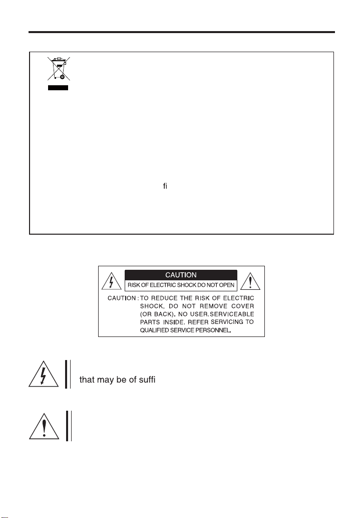
This symbol is intended to alert the user to the presence of uninsulated “dangerous voltage” within the product’s enclosure
cient magnitude to constitute a risk of electric
shock to persons.
This symbol is intended to alert the user to the presence of
important operating and maintenance (servicing) instructions in
the literature accompanying the appliance
5
Page 6
IMPORTANT SAFETY INSTRUCTIONS
1) Read these instructions.
2) Keep these instructions.
3) Heed all warnings.
4) Follow all instructions.
5) Do not use this apparatus near water.
6) Clean only with dry cloth.
7) Do not block any ventilation openings. Install in accordance
with the manufacturer’s instructions.
8) Do not install near any heat sources such as radiators, heat registers,
ers) that produce heat.
9) Do not defeat the safety purpose of the polarized or grounding-type plug. A
polarized plug has two blades with one wider than the other. A grounding type plug
has two blades and a third grounding prong. The wide blade or the third prong are
provided for your safety. If the provided plug does not t into your outlet, consult an
electrician for replacement of the obsolete outlet.
10) Protect the power cord from being walked on or pinched particularly at plugs,
convenience receptacles, and the point where they exit from the apparatus.
ed by the manufacturer.
ed by the
manufacturer, or sold with the apparatus. When a cart is used,
use caution when moving the cart/apparatus combination to
avoid injury from tip-over.
13) Unplug this apparatus during lightning storms or when unused for long
periods of time.
ed service personnel. Servicing is required when
the apparatus has been damaged in any way, such as power-supply cord or plug
is damaged, liquid has been spilled or objects have fallen into the apparatus, the
apparatus has been exposed to rain or moisture, does not operate normally, or has
been dropped.
6
Page 7

1. Overview
1.1 Features
DPZ36WO23:
- 600 TVL Resolution
- 230X Zoom (23X Optical, 10X Digital)
DPZ36WO30:
- 700 TVL Resolution
- 300X Zoom (30X Optical, 10X Digital)
Common Features:
- Autofocus, High Resolution Integrated Color Camera
- WDR (Wide Dynamic Range)
- Day & Night (Auto/BW/Color)
- Pan 360°Endless Rotation
- Tilt 180°Vector scan available
- 210 Preset Positions (except Short-cut command)
- 8 Auto Scan
- 8 Pattern
- 8 Tours consist of Presets, Patterns and Scans
- 4 Alarm Input (Off/NC/NO) and 1 Alarm Output (Off/NC/NO)
- User programmable setting
(Preset, Auto Scan, Pattern, Tour, Home Function, Alarm Action, etc)
- Programmable PTZ Speed: Proportional to Zoom ratio, changeable preset speed
- Multi-language OSD Support
- Private Mask Zone Support
- Standard protocol including Pelco-D/P
- Up to 255 Camera ID’s
- RS-485 Receiver
- AC 24V Only
- IP Rating: IP66 (Weatherproof)
7
Page 8
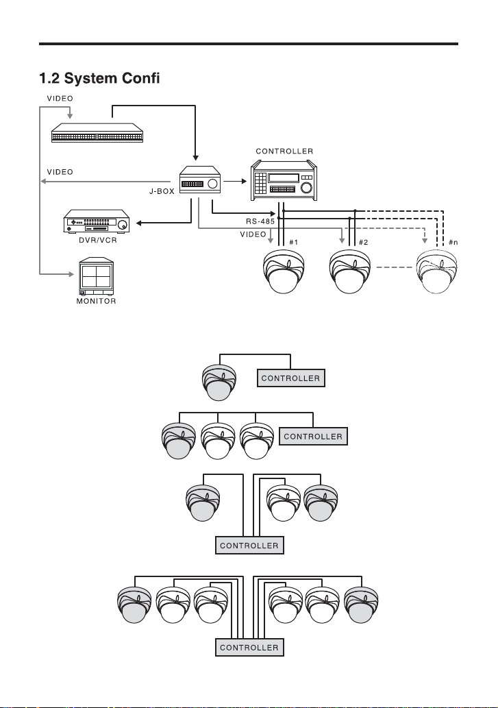
1. Overview
guration
MULTI PLEXER
1.3 Termination Settings
8
Page 9
2. Installation and Connection
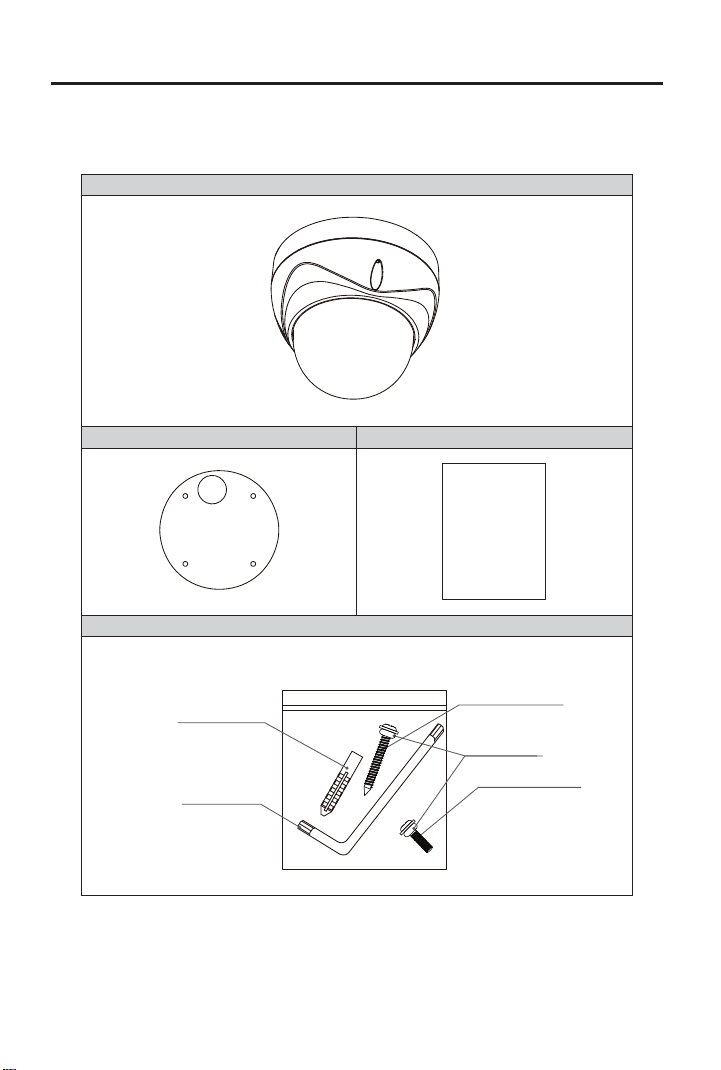
2.1 Package Contents
Camera
Mounting Template
Manual
Screws / Plastic anchors / Allen Key / O-Ring
Plastic anchors
(6x30 - 4ea)
Allen-Key
Screws
(#8(Ø4.2)x32 - 4ea)
O-Ring(8ea)
Screws(M4x12-4ea)
9
Page 10
2. Installation and Connection
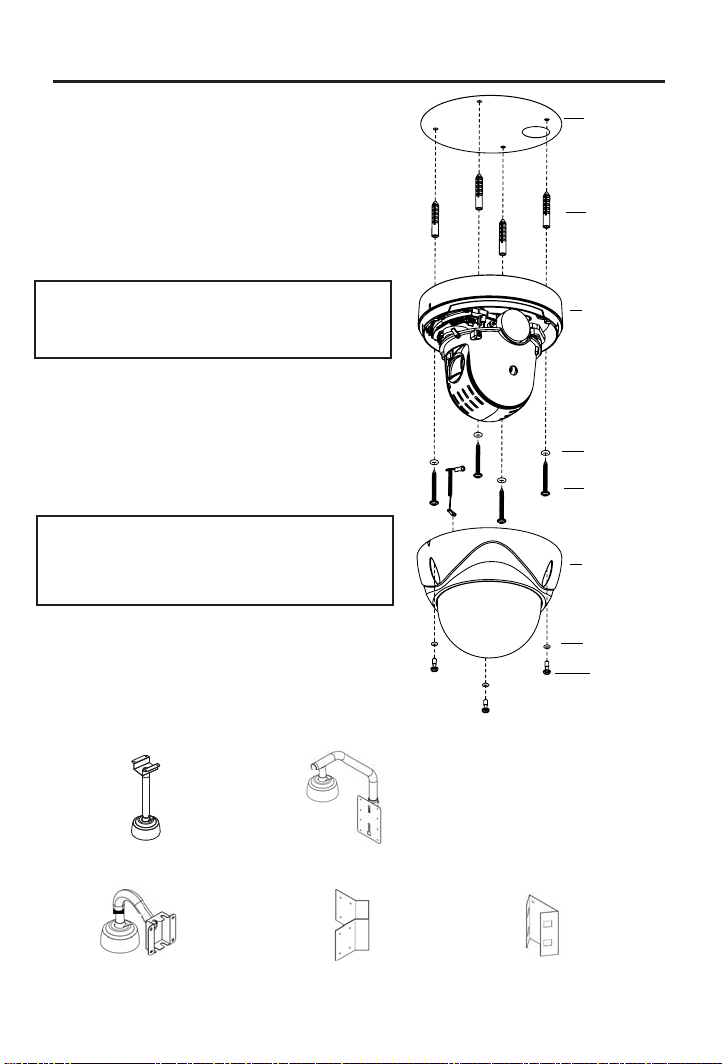
2.2 Surface Mounting
1 - Select a location that can support the weight
of the camera.
2 - Use the mounting template to create holes for
the mounting screws and cable. Insert the
anchors(4).
3 - Run the cables through the cable hole and
connect the cables as shown in
{2.4.5 Connection Diagram} on page 11.
Caution: Do not connect power to the
camera before completing the entire
installation.
4 - Remove the dome cover. Remove the
internal foam packaging. To prevent scratches,
do not remove the film on the outside of the
dome cover before completing the installation.
5 - Firmly attach the Camera Base to the surface
using the mounting screws(4) with o-rings
attached.
Caution: Make sure the o-rings are
attached to the mounting screws and
torx screws before mounting to provide
a weatherproof seal.
6 - If necessary, use the internal Dip Switches
to set the camera ID and protocol according
to {2.5 Setting Dome Camera} on page 12.
7 - Attach the Dome Cover to the Camera Base
using the torx screws(3) with o-rings attached.
2.3 Mounting Accessories
Mounting
Template
Anchors(4)
Camera
Base
O-Rings(4)
Mounting
Screws(4)
Dome
Cover
O-Rings(3)
Torx
Screws(3)
MNTZ36C Ceiling Mount
MNTZ36W Wall Mount
MNTZ36PP Parapet Mount
(Special Order)
MNTZ36R Corner Adapter
(Requires MNTZ36W)
10
MNTZ36P Pole Adapter
(Requires MNTZ36W)
Page 11
2. Installation and Connection
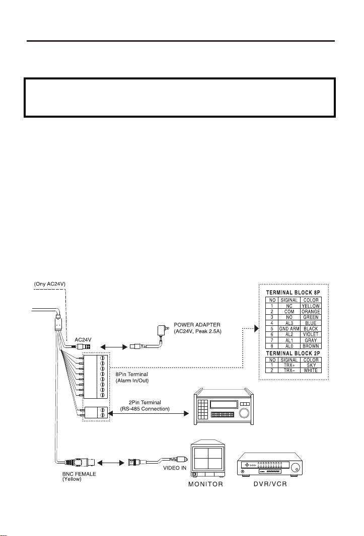
2.4 Connection Interface and Wiring Cables
Caution
Remove the protection sheet (PE form) before connecting power to the camera.
Do not connect the power cable until all other connections have been completed.
2.4.1 Connecting the RS-485 lines
The dome camera can be controlled remotely by an external device or control system such as
a controller using RS-485 half duplexer (RS-485 Connection). A repeater is recommended to
extend over 1.2km.
2.4.2 Connecting Video Jack
Connect the video Jack (BNC connector) to the monitor or video input of the DVR.
2.4.3 Connecting Alarms
Alarm In: You can use external devices to trigger the dome camera to react to events.
Mechanical or electrical switches can be wired to the AI and Ground pins.
Alarm Out: The dome camera can activate external devices such as buzzer. Connect the device
to NO (or NC) and COM pins.
2.4.4 Connecting the Power
Connect the power jack of a AC24V adapter or power source to the dome camera.
2.4.5 Connection Diagram
11
Page 12
2. Installation and Connection
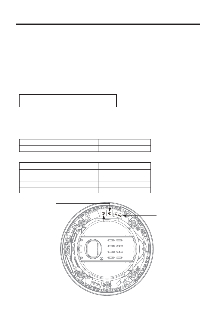
2.5 Setting Dome Camera
The device can communicate with external switching devices such as multiplexers or DVR’s by
setting the Rotary switch and Dip switch. Refer to tables below for setting the dome camera ID
and protocol selection. Total length of the cable for communication should not exceed 1km.
2.5.1 Setting the address (ID) of dome camera
To prevent wrong operation and malfunction, each dome camera has a unique address (ID).
The default setting is 0[ID001]
Dome Camera ID Setting (Rotary Switch, SW301, SW302)
X16 X1
SW301 SW302
The value of rotary switches is in hexadecimal. For example, if SW301 = A and SW302 = F then
the ID = 175(AF).
2.5.2 Setting the protocol of dome camera
Dome Camera Protocol Setting (Dip Switch, SW303)
No1 No2 Protocol
Off Off Pelco-D/Pelco-P
Dome Camera Baud Rate Setting (Dip Switch, SW303)
No3 No4 Baud Rate(bps)
Off Off 2400
Off On 4800
On Off 9600
On On 38400
Dome Camera Termination Setting Off/On (NO5, Dip Switch, SW303)
SW301
.
SW302
SW303
12
Page 13

3. Program and Operation
[OSD Menu Structure]
- Main Menu/Editing Title
- Operation Menus
X23(X30) MINI SPEED DOME
V x.xx.xx
RS485/2400
ID001
NTSC
MAIN MENU
SYSTEM SETUP
DISPLAY SETUP
CAMERA SETUP
DOME MOTION
PRESET SETUP
PATTERN SETUP
TOUR SETUP
SCAN SETUP
ALARM SETUP
EXIT
TITLE
ABCDEFGHIJKLMNOPQRSTUVWXYZ
0123456789/+-=:?!#.,"~()
SELECT: (MOVE)
SET/CLEAR: (TELE/WIDE)
SAVE: (NEAR)
EXIT: (FAR)
13
Page 14

3. Program and Operation
REFRESH MODE : ON
REFRESH TIME:
PRESET MASK : OFF
PROP PAN/TILT : ON
14
Page 15

3. Program and Operation
15
Page 16

3. Program and Operation
3.1 Getting Started
Before installing and operating the dome camera, please read this Instruction Manual carefully.
This dome camera can be operated using two methods:
You should install and connect the dome to an interface device before using this operating guide.
See [2. Installation and Connection].
Once installed, apply power to the dome. The start-up screen is displayed on the monitor.
- Use hot keys [See Appendix]
- Use OSD Menu on the monitor
* Notice:
* Notice:
You must save changes in each sub-menu and edit menu. You may need to save
settings twice.
For example, after you set the position of a preset, you must save the position in the preset edit
window and then save changes in the Preset Setup menu again.
To stop an action or alarm, press [ESC] button or [96+Preset]. The dome goes to
manual mode or pauses temporarily (about 10sec in Alarm mode)
These symbols refer to the following joystick actions:
: move joystick up and down
: move joystick left and right
: move joystick right
[Tele/Wide]: twist joystick clockwise or counter-clockwise for zooming
ned key.
3.2 Main Menu
3.2.1 Acessing the Main Menu [95] + [Preset]/ [Menu]
When you use Pelco-D and Pelco-P protocol with your controller, you can access the main
menu on your monitor by pressing the key [95] + [Preset] or pressing and holding the
[Menu] key for 2 seconds.
MAIN MENU
SYSTEM SETUP
DISPLAY SETUP
CAMERA SETUP
DOME MOTION
PRESET SETUP
PATTERN SETUP
TOUR SETUP
SCAN SETUP
ALARM SETUP
EXIT
: move joystick up and down to select items.
[Open]/ [Near]: move joystick right or press [Open] or [Near] to select sub-menus.
[Close]/[Far]: Exit Main Menu.
16
Page 17

3. Program and Operation
3.2.2 Editing TITLE
TITLE
ABCDEFGHIJKLMNOPQRSTUVWXYZ
0123456789/+-=;?#.,"~0
SELECT : (MOVE)
SET/CLEAR: (TELE/WIDE)
SAVE : (NEAR)
EXIT : (FAR)
The Title edit menu can be used in the setup titles for Presets, Patterns, Tours, and Scans.
- Select {Title} in the appropriate menu and move the joystick to the right.
- Move the joystick right, left, up or down to select a character.
- Press [Tele] button to input a character and [Wide] button to cancel the character.
- When the label is completed, use [Near] or use the joystick to save the selected title.
- If you want to cancel the selected title, return to the previous menu using [Far] button.
3.3 System Setup Menu
: move joystick up and down to select items.
: move joystick left and right to change settings.
[Open]/ [Near]: move joystick right to open sub-menus.
[Close]/ [Far]: move joystick to cancel or to exit current menu (back).
SYSTEM SETUP
INFO.
REBOOT
INITIALZE
PASSWORD
EXIT
3.3.1 System Information
X23(X30) MINI SPEED DOME
V x.xx.xx
RS485/2400
ID001
NTSC
The system Information displays model name/Version/Protocol/Communication Type/
Camera ID No./System. This information is for reference only, you cannot change settings through
the System Information screen. Use the following steps to display the System Information screen.
- Enter into {Main Menu}.
- Select {System Setup} using the joystick [
- Select {Info} using the joystick ].[
- Press [Far] button to return to the System Setup menu.
].
17
Page 18

3. Program and Operation
3.3.2 Reboot
REBOOT
CONTINUE?
YES : NEAR
NO : FAR
Reboot the system if operation becomes unstable or encounters errors.
Rebooting the system will turn the camera on and off without changing settings.
- Enter into {Main Menu}
- Select {System Setup} then {Reboot} using the joystick.
- To {Reboot} the system, press the [Near] key.
- To cancel, press [Far] key.
3.3.3 Initialize
INITIALIZE
ALL : NO CLR
CAM : NO CLR
PRESET : NO CLR
TOUR : NO CLR
PATTERN : NO CLR
SCAN
: NO CLR
ETC
: NO CLR
SAVE : OPEN
BACK : CLOSE
Use initalize to reset settings to factory defaults.
- Enter into {Main Menu}
- Select {System Setup} and select {Initalize} using the joystick [ ].
- Select items to be initialized by highlighting them and then move the joystick right to select {Clear}.
- Press [Open] button to initalize selections and select [Near] to continue. Press [Far] to cancel.
[ALL]: Clear All saved items (CAM/PRESET/TOUR/PATTERN/SCAN)
[CAM]: Clear Camera related settings.
[PRESET]: Clear saved Presets. (To clear individual presets, refer to PRESET Menu)
[TOUR]: Clear saved Tours.
[PATTERN]: Clear saved Patterns.
[SCAN]: Clear saved Scan items.
[ETC]: Clear other setting value except items of Camera & PTZs
(CAM status and saved data of PRESET, TOUR, PATTERN and SCAN)
18
Page 19

3. Program and Operation
3.3.4 Entering a Password
* Note:
0000 is the default password.
PASSWORD
CURRENT : ...
ENABLE : DISABLE
NEW : ...
CONFIRM : ...
0123456789
-SET/CLEAR : (TELE/WIDE)
-EXIT : (FAR)
To prevent unauthorized changes to settings, you can enable password protection.
When password protection is enabled, you must enter the password to enter the Main Menu.
Passwords must be 4 characters long.
- Enter into {Main Menu}
- Select {System Setup} and select {Password} using the joystick
].
[
- Enter the current password (default: 0000) by moving the joystick left and right to highlight numbers
and press [Tele] to enter numbers.
- Highlight {Enable} and move the joystick left or right to select {Enable} to enable password protection.
Move the joystick down to enter the new password.
- Enter the New password by moving the joystick left and right to highlight numbers
and press [Tele] to enter numbers. Re-enter the New password under Confirm.
- Press [Far] to exit the menu and save changes.
3.4 Display Setup Menu
DISPLAY SETUP
OSD SETUP
PRIVACY ZONE
IMAGE SETUP
MOTION / FACE
LANGUAGE: ENGLISH
EXIT
: move joystick up and down to select items.
: move joystick left and right to change settings.
[Open]/ [Near]: move joystick right to enter sub-menus.
[Close]/ [Far]: Exit current menu without saving changes.
3.4.1 Language
- Enter into {Main Menu}
- Select {Display Setup} and highlight {Lanugage} using the joystick.
- If you want to use another language, move the joystick left and right to select.
Available Languages: English/Chinese/Russian/Spanish/German/Italian/French/Dutch.
19
Page 20

3. Program and Operation
3.4.2 OSD Setup
OSD SETUP
LABEL POSITION : OFF
TIME : ON
ZOOM : OFF
ID : ON
MODE : ON
ANGLE : 3SEC
SAVE : OPEN
BACK : CLOSE
- CHANGE : (LEFT/RIGHT)
- TO SETUP : (TELE)
OSD setup allows you to program how labels are displayed on the monitor.
Labels can be configured for Title, Dwell Time, Zoom ratio, Camera ID, Operation Mode
and PTZ Angle. Label position can be adjusted.
- Enter into {Main Menu}
- Select {Display Setup} and select {OSD Setup} using joystick [
- Highlight labels using the joystick to configure:
- Move the joystick left or right [ ]
- Press [Tele] button to edit the position of labels. Move the label with the joystick and
press [Far] to return to the OSD Setup menu.
- Press [Open] button to save changes.
- Press [Close] button to return to the previous menu without saving changes.
3.4.3 Privacy Zone Setup
PRIVACY ZONE SETUP
PRIVACY.00 : NOT
USED
EDIT :
DISPLAY :
WIDTH :
HEIGHT :
CLEAR
SAVE : OPEN
BACK : CLOSE
CHANGE : (LEFT/LIGHT)
A Privacy Zone allows you to program four-sided zones that cannot be viewed by operators.
Privacy masks can be moved using pan and tilt controls using the joystick and re-sized using the
zoom controls [Tele/Wide]. Privacy masks stay in position when adjusting the camera pan/tilt
and change size when adjusting the zoom ratio. A maximum of 15 privacy mask zone can be
displayed.
It is recommended that you set the size of privacy masks to at least twice the height and width
of the object/area you would like to mask.
- Enter into {Main Menu}
- Select {Display Setup} and then {Privacy Zone} using the joystick
- Move the joystick left or right to select a privacy mask ID[00~14] to edit.
- To program a privacy mask, select {Edit}, use the pan/tilt controls to move to a target, and use
the zoom controls [Tele/Wide] to adjust the mask size. Press [Near] to save the privacy mask.
- After editing a mask, you can use the {Width} and {Height} controls to adjust the size.
- Set {Display} to On to display the mask on the screen.
- Select {Clear} to delete a saved privacy mask.
- Press [Open] button to save settings.
- Press [Close] button to return to previous menu without saving.
-
- TITLE - MODE -
- DTIME ERROR MSG
- EXIT : FAR
- ID ZOOM - ANGLE -
]
to enable/disable label display.
PRIVACY ZONE SETUP
PRESS MOVE KEY
SAVE : NEAR
EXIT : FAR
[
20
].
Page 21

3. Program and Operation
3.4.4 Image Setup
IMAGE SETUP
MIRROR : NORMAL
SAVE : OPEN
BACK : CLOSE
This menu allows you to mirror the image horizontally, vertically, or both.
- Enter into {Main Menu}
- Select {Display Setup} and then select {Image Setup} using the joystick[
- Highlight {Mirror} and select Normal, Horizontal, Vertical, or H/V (Horizontal and Vertical).
- Press [Open] button or use joystick to save settings
- Press [Close] button or use joystick to return to the previous menu without saving changes.
3.4.5 Motion Detection/Face Detection (MD/FD)
The camera can monitor the image for movement or faces. When triggered, it sends an alarm using
the OSD and/or Alarm Out. The sensitivity of motion/face detection can be adjusted between 0 and
15 (a greater sensitivity value means alarms will be triggered more easily).
To stop alarms temporarily (about 10sec), press [ESC] button or [96+preset]. Face detection may
* Note:
be triggered by objects that appear similar to human faces.
- Enter into {Main Menu}
- Select {Display Setup} and then {MD/FD} using the joystick.
- Highlight {MD/FD} and select Off, Motion-D, or Face-D to enable motion or face detection.
- Highlight {Alarm} and select OSD to have alarms appear on the OSD, Alarm Out to send an
alarm message, or OSD + Al. Out for both an OSD alert and Alarm Out message.
- Highlight {Sensitivity} and select a sensitivity between 0 and 15 (greater sensitivity means alarms
are triggered more easily).
- Highlight {ATime} and select the duration of alarms in seconds.
- Press [Open] or use the joystick to save settings.
- Press [Close] or use the joystick to return to the previous menu without saving changes.
MD/FD
MD/FD : OFF
SENSITIVITY :
ALARM :
ATIME :
SAVE : OPEN
BACK : CLOSE
].
21
Page 22

3. Program and Operation
3.5 Camera Setup Menu
CAMERA SETUP
FOCUS/ZOOM
W-BALANCE
EXPOSURE
DAY/NIGHT
ADVANCE
WDR/DNR
EXIT
: move joystick up and down to select items.
/
: move joystick left and right to change settings.
/
/ [Open]/ [Near]: move joystick right to enter sub-menus.
/ [Close]/ [Far]: move joystick to cancel or to exit current menu without saving changes.
3.5.1 Focus/Zoom
Auto Focus allows the lens to remain in focus automatically during zoom and pan/tilt functions.
optical zoom. There are four modes (Slow, Normal, Fast, and V-Fast).
- Enter into {Main Menu}.
- Select {Camera Setup} and then select {Focus/Zoom} using joystick[
- Highlight {Focus} and select the focus mode: Auto, Manual, or Semi-Auto.
- Highlight {Zoom Speed} and select V-Fast, Fast, Normal or Slow.
- Highlight {D.Zoom} and select On/Off to enable/disable digital zoom.
- Highlight {Refresh Mode} and select On/Off to enable/disable Focus Refresh.
- Highlight {Refresh Time} and select the amount of time in between Focus Refreshes.
- Press [Open] button or use joystick to save settings.
- Press [Close] button or use joystick to return to previous menu without saving changes.
3.5.2 WB Setup (White Balance Setup)
AWB automatically processes the image to retain color balance over a color temperature range.
* Auto Trace White balance (ATW): Aligns the white balance automatically (2,300 to 11,000 K).
* Indoor: 3200 K Base Mode.
* Outdoor: 5400 K Base Mode.
* Onepush WB mode: The white balance is aligned when Onepush is selected from the menu.
* Manual WB mode: Red and Blue gain values can be set by user, 0 ~ 255.
* Auto White Balance mode (AWB): Wide range auto white balance mode. In this mode, the white balance is
performed at a faster operating speed than ATW.
- Enter into {Main Menu}
- Select {Camera Setup} and then select {W-Balance} using the joystick [
- Highlight {Mode} and select AWB, Indoor, Outdoor, Onepush, ATW, or Manual.
- If you select Manual, highlight {R Gain} and {B Gain} and adjust the blue/red gain as needed.
- Press [Open] button or use joystick to save settings.
- Press [Close] button or use joystick to return to previous menu without saving changes.
FOCUS/ZOOM SETUP
FOCUS : AUTO
ZOOM SPD : V-FAST
D.ZOOM : OFF
REFRESH MODE : ON
REFRESH TIME : 0DAY 12HOUR
SAVE : OPEN
BACK : CLOSE
ne how fast the dome will go from full wide zoom to the maximum
WB SETUP
MODE : AWB
R GAIN :
B GAIN :
SAVE : OPEN
BACK : CLOSE
22
].
].
Page 23

3. Program and Operation
3.5.3 AE Setup (Auto Exposure Setup)
AE SETUP
MODE : FULL AUTO
SHUT :
AGC GAIN :
AGC MAX : HIGH
DSS : OFF
BRIGHT : 06
SAVE : OPEN
BACK : CLOSE
Shutter speed is the duration of the electronic shutter. Set the shutter speed to operate
automatically (Full Auto) or manually (Numeric Value)..
The AGC (Automatic Gain Control or AGC Max Gain) adjusts the brightness of the picture. The
brightness increases as the number gets higher.
When the Shutter Mode is set to Full Auto, DSS can be turned off or on (2x ~ 128x).
- Enter into {Main Menu}.
- Select {Camera Setup} and then select {Exposure} using joystick[
].
- Highlight {Mode} and select Full Auto, Manual, or Shutter PRI. Adjust the remaining settings as
needed. See the table below for details on which settings can be adjusted in each mode and the
default values for each.
- Press [Open] button or use joystick to save settings.
- Press [Close] button or use joystick to return to the previous menu without saving changes.
AE Mode Full Auto Manual SHUT FIX WDR
(1/1~1/100,000)
Shutter
AGC Gain
AGC Max
(0x2~0x128Fld)
DSS
(00~15)
Bright
(00~36dB)
(Off/Low/Mid/High/Super)
X O (1/1000) O (1/1000) X
X O (06dB) X X
O (default: High) X O (High) O
O (Off) X X X
O (06) X O (06) O
Avaliable Options for each Auto Exposure Mode and Default Values (in Parenthesis)
3.5.4 Day / Night Setup
D/N SETUP
DAY/NIGHT : AUTO
D&N DETECT : AUTO
D/N DTIME : 03
SAVE : OPEN
BACK : CLOSE
The Day / Night function improves the camera’s sensitivity at night or when the brightness level
of the ambient environment is low. When Auto is selected, Day / Night filter is automatically
engaged/disengaged according to the luminance level.
- Enter into {Main Menu}.
- Select {Camera Setup} and select {Day/Night} using joystick [
- Highlight {Day/Night} and select Auto, Day, or Night.
- Highlight {D&N Detect} and select Auto, Sensor, or Video.
- Highlight {D/N DTime} and select the time it takes for the camera to switch between day and night
mode.
- Press [Open] button or use joystick to save settings.
- Press [Close] button or use joystick to return to the previous menu without saving changes.
.
23
Page 24

3. Program and Operation
3.5.5 Advanced Setup
ADVANCED SETUP
SHARPNESS : 10
BACKLIGHT : OFF
SAVE : OPEN
BACK : CLOSE
The Backlight Compensation function increases the brightness of the overall screen to compensate
for a loss of dark detail when subjects are shot in a backlit environment.
Sharpness enhances picture detail by increasing the aperture gain of the camera and sharpening
the edges in the picture.
- Enter into {Main Menu}
- Select {Camera Setup} and then select {Advanced} using the joystick[
- Highlight {Sharpness} and adjust the sharpness level as needed.
- Highlight {Backlight} and select On/Off to enable/disable Backlight Compensation.
- Press [Open] button or use joystick to save settings
].
- Press [Close] button or use joystick to return to previous menu without saving changes.
3.5.6 WDR/DNR Setup
WDR/DNR
WDR SETUP : OFF
WDR LEVEL :
DNR SETUP : OFF
DNR LEVEL :
SAVE : OPEN
BACK : CLOSE
When both high-brightness subjects and low-brightness subjects have been shot at the same
time, overexposure in the high-brightness subjects or loss of dark detail in the low-brightness
subjects may occur. The WDR (Wide Dynamic Range) function creates images free from overexposure or loss of dark detail by combining two images after tripping the shutter for a long
exposure time and for a short exposure time in one
DNR (Digital Noise Reduction) can be set between 0 and 15. When gain level is higher,
DNR will reduce the noise to make the image clearer.
- Enter into {Main Menu}.
- Select {Camera Setup} and then select {WDR/DNR} using joystick
- Highlight {WDR Setup} and select On/Off to enable/disable Wide Dynamic Range.
- Highlight {WDR Level} and adjust as needed.
- Highlight {DNR Setup} and select On/Off to enable/disable Digital Noise Reduction.
- Highlight {DNR Level} and adjust as needed.
- Press [Open] button or use joystick to save settings.
- Press [Close] button or use joystick to return to previous menu without saving changes.
eld.
].
24
Page 25

3. Program and Operation
3.6 Dome Motion Menu
DOME MOTION SETUP
GENERAL SETUP
MOTION SETUP
HOME ACTION
CALIBRATION
EXIT
/ : move joystick up and down to select items.
/ : move joystick left and right to change settings.
/ [Open]/ [Near]: move joystick right to enter sub-menus.
/ [Close]/ [Far]: move joystick to cancel or to exit current menu without saving changes.
3.6.1 General Setup
GENERAL SETUP
POWER-UP ACT. : ON
TURBO SPEED : ON
PRESET SPEED : FAST
PRESET MASK : OFF
SAVE : OPEN
BACK : CLOSE
This menu controls general motion settings.
Power-up Action (Power-up Act.) is a function (preset, tour, pattern and scan) performed when the
power is re-cycled or after alarm action. The following settings are available. Set the dome
‘On’ to resume its prior activity.
- Use the joystick [ ] to select On/Off.
Turbo Speed enables/disables turbo speed for manual pan/tilt operations.
- Use the joystick [
] to select On/Off.
Preset Speed allows you to select the preset speed.
- Use the joystick to select {Preset Speed} and select Fast, Normal, or Slow.
When Preset Mask is on, the camera will show a gray screen while moving between presets.
When each preset is reached, the camera shows the image for the duration of the dwell time.
- Use the joystick
- Press [Open] button or use joystick to save settings
to select {Preset Mask} and select On or Off.
- Press [Close] button or use joystick to return to the previous menu without saving changes.
25
Page 26

3. Program and Operation
3.6.2 Motion Setup
MOTION SETUP
PROP. PAN/TILT : ON
AUTO FILP : ON
OVER TILT : MODE 1
SAVE : OPEN
BACK : CLOSE
Proportional Pan/Tilt (Prop. Pan/Tilt) adjusts the manual pan/tilt speed according to the zoom level.
- Highlight {Prop. Pan/Tilt} and use the joystick to select On/Off.
Auto-Flip automatically reverses the image when the camera passes the top of the tilt arc
(90 degrees). This allows the camera to see objects with the correct orientation after tilting
more than 90 degrees.
- Highlight {Auto Flip} and use the joystick to select On/Off.
Over-Tilt restricts the vertical view angle to prevent the image being cut off by the dome housing.
- Highlight {Over Tilt} and use the joystick to select Mode 0 / Mode 1 / Mode 2.
- Press [Open] button or use the joystick to save settings.
- Press [Close] button or use the joystick to return to the previous menu without saving changes.
3.6.3 Home Action Setup
HOME ACTION SETUP
ACTION : HOME
NUMBER :
TIME : 010 MIN
MODE : OFF
SAVE : OPEN
BACK : CLOSE
Home Action allows you to set a default action (e.g. Preset, Tour, or Auto Scan) that the camera
will perform after the joystick control has been idle for a predetermined amount of time.
The idle time can be set from 1 minute to 60 minutes.
In order to call an action (Preset, Pattern, Tour or Scan), you must save Preset, Pattern, Tour,
* Note:
or Scan
rst.
- Enter into {Main Menu}.
- Select {Dome Motion} and then {Home Action} using the joystick[ ].
- Highlight {Action} and selct Home, Preset, Scan, or Tour. If Home is selected, the camera will
return to the default home position (Pan 0˚ / Tilt 8˚) after the idle time.
- Highlight {Number} and select the desired Preset, Scan, or Tour.
- Highlight {Time} and select the idle time.
- Highlight {Mode} and select On/Off to enable/disable Home Action.
- Press [Open] button or use the joystick to save settings.
- Press [Close] button or use the joystick to return to the previous menu without saving changes.
26
Page 27

3. Program and Operation
3.6.4 Calibration Setup
CALIBRATION SETUP
AUTO CAL : AUTO
ERROR MSG DISP : OFF
CALIBRATION
SAVE : OPEN
BACK : CLOSE
Calibration allows you to correct Pan/Tilt control errors.
- Enter into {Main Menu}.
- Select {Dome Motion} and then select {Calibration} using the joystick [ ].
- Highlight {Auto Cal} and select Auto for Auto Calibration or Manual for Manual Calibration.
When Auto Calibration is selected the camera will automatically calibrate when errors are detected.
When Manual Calibration is selected, you must manually initiate the calibration process. To
manually calibrate the camera, select {Calibration} using the joystick [ ] and press [Near] to confirm.
- Highlight {Error Msg Disp} and select On/Off to enable/disable OSD messages when errors are
detected.
- Press [Open] button or use the joystick to save settings.
- Press [Close] button or use the joystick to return to the previous menu without saving changes.
3.7 Preset Setup
PRESET SETUP
NO. 001 : NOT USED
EDIT :
TITLE :
D TIME :
CLEAR
SAVE : OPEN
BACK : CLOSE
CONTINUE?
YES : NEAR
NO : FAR
/ : move joystick up and down to select items.
/ : move joystick left and right to change settings.
/ [Open]/ [Near]: move joystick right to enter sub-menus.
/ [Close]/ [Far]: move joystick to cancel or to return to previous menu without saving changes.
The camera can have up to 210 preset positions. Preset positions include Pan/Tilt/Zoom setting.
27
Page 28

3. Program and Operation
3.7.1 Saving Presets
PRESET SETUP
NO. 001 : NOT USED
EDIT :
TITLE :
D TIME :
CLEAR
SAVE : OPEN
BACK : CLOSE
- Enter into {Main Menu}
- Select {Preset Setup} using the joystick [ ].
PRESET SETUP
PRESS MOVE KEY
SAVE : NEAR
BACK : FAR
- Highlight {No.} and move the joystick left and right to select the preset you would like to edit.
- Select {Edit} to edit the preset. Use the joystick to move the camera into the desired position
and press [Near] to save.
- Select {Title} to create a Preset Title (Optional). See [3.2.2 Editing Title] for details.
- Highlight {DTime} and just the joystick to set the dwell time for the preset.
- Press [Open] button or use the joystick to save settings.
- Press [Close] button or use the joystick to return to the previous menu without saving changes.
Note: Select {Clear} to clear the selected Preset.
3.8 Pattern Setup
PATTERN SETUP
NO.001 : NOT USED
EDIT :
TITLE :
TIME :
CLEAR
SAVE : OPEN
BACK : CLOSE
/ : move joystick up and down to select items.
/ : move joystick left and right to change settings.
/ [Open]/ [Near]: move joystick right to enter sub-menus.
/ [Close]/ [Far]: move joystick to cancel or to exit current menu (Back).
A Pattern allows you to save a series of Pan/Tilt/Zoom movements. The camera can save
up to 8 patterns.
28
Page 29

3. Program and Operation
Use the following steps to program a Pattern.
PATTERN SETUP
NO.001 : NOT USED
EDIT :
TITLE :
TIME :
CLEAR
SAVE : OPEN
BACK : CLOSE
PTIME: 022
START POSITION SETUP
PATTERN SETUP
PRESS MOVE KEY
START : (NEAR)
SAVE : (NEAR)
EXIT : (FAR)
- Enter into {Main Menu}.
- Select {Pattern Setup} using the joystick [ ].
- Highlight {No.} and select the number of the pattern you would like to edit.
- Select {Edit} to edit the pattern. Use the joystick to move to the desired start position and press
[Near] to start programming the pattern. Move the joystick to program the pattern and press
[Near] when finished to save the pattern.
- Select {Title} to create a Pattern Title (Optional). See [3.2.2 Editing Title] for details.
- Press [Open] or use the joystick to save settings.
- Press [Close] or use the joystick to return to the previous menu without saving changes.
Note: Select {Clear} to clear the selected Pattern. Time refers to the duration of the pattern.
Patterns cannot be longer than 60 seconds.
3.9 Tour Setup
TOUR SETUP
NO. 001 : NOT USED
... ... ... ... ... ... ...
... ... ... ... ... ... ...
... ... ... ... ... ... ...
... ... ... ... ... ... ...
CLEAR
SAVE : OPEN
BACK : CLOSE
- CHANGE ID : (TELE/WIDE)
- CHANGE ACTION : (NEAR)
/ : move joystick up and down to select items.
/ : move joystick left and right to change settings.
/ [Open]/ [Near]: move joystick right to enter sub-menus.
/ [Close]/ [Far]: move joystick to return to previous menu without saving changes.
The camera can save up to 8 tours, with up to 28 items (Preset, Pattern, or Scan) each.
In order to call an action (Preset, Pattern or Scan), you must save the action first.
* Notice:
- Enter into {Main Menu}.
- Select {Tour Setup} using the joystick [ ].
- Highlight {No.} and select the number of the tour you would like to edit.
- Move the joystick to select items in the tour. Select saved actions by pressing [Tele/Wide].
Change the action type by pressing [Near].
- Press [Open] or use the joystick to save settings.
- Press [Close] or use the joystick to return to the previous menu without saving changes.
Note: Select {Clear} to clear the selected Tour.
29
Page 30

3. Program and Operation
3.10 Auto Scan Setup
SCAN SETUP
NO. 001 : NOT USED
EDIT :
SPEED :
DTIME :
DIRECTION :
MODE :
CLEAR
SAVE : OPEN
BACK : CLOSE
/ : move joystick up and down to select items.
/ : move joystick left and right to change settings.
/ [Open]/ [Near]: move joystick right to open sub-menus.
/ [Close]/ [Far]: move joystick to cancel or return to previous menu without saving changes.
An Auto Scan is a PTZ function that can be moves the camera from one position to another
position. The camera can save a maximum of 8 Auto Scans. Scan Speed can be adjusted from
1 ~ 35 degrees per second. Use the following steps to create an Auto Scan.
START POSITION SETUP
PRESS MOVE KEY
SAVE : (NEAR)
BACK : (FAR)
- Enter into {Main Menu}.
STOP POSITION SETUP
PRESS MOVE KEY
SAVE : (NEAR)
BACK : (FAR)
- Select {Scan Setup} using the joystick [ ].
- Highlight {No.} and select the number of the scan you would like to edit.
- Move the joystick to select the desired start position and press [Near] to save. Move the
joystick to the desired stop position and press [Near] to save.
Note: Mode represents one of the following:
- Coming/Going: Camera moves between start and stop position. Start and stop position
must be different.
- Endless: Camera scans in a circular pattern. Start and stop position must be identical.
Use the {Direct} setting to set the scan direction as CW (Clockwise) or CCW
(Counterclockwise).
- Highlight {Speed} and select the scan speed in degrees per second.
- Highlight {DTime} and select the scan dwell time.
- Press [Open] or use the joystick to save settings.
- Press [Close] or use the joystick to return to the previous menu without saving changes.
30
Page 31

3. Program and Operation
3.11 Alarm Setup
The Alarm Setup menu allows you to configure alarm inputs and outputs.
ALARM SETUP
NO. 001 : NOT USED
IN :
OUT :
PRIORITY :
ACTION :
NUMBER :
ATIME :
SAVE : OPEN
BACK : CLOSE
- SET/CLEAR : (TELE/WIDE)
/ : move joystick up and down to select items.
/ : move joystick left and right to change settings.
/ [Open]/ [Near]: move joystick right to ener sub-menus.
/ [Close]/ [Far]: move joystick to return to previous menu without saving changes.
- Enter into {Main Menu}.
- Select {Alarm Setup} using the joystick [ ].
- Highlight {No.} and select the number of the alarm you would like to configure.
- Highlight {In} and select the alarm input type: N.O. (Normally Open) or N.C. (Normally Closed).
- Highlight {Out} and select the alarm output: On/Off.
- Highlight {Priority} and set the alarm priority between 1 and 4.
- Highlight {Action} and select the type of action that the alarm will trigger: Off, Preset
Pattern, Scan, or Tour.
- Highlight {Number} and select the number of the action the alarm will trigger.
- Highlight {ATime} and select the Action (dwell) time:
Time Out (3~60 sec): This is activated during a selected dwell time when an alarm is triggered.
Momentary (On): When alarm is triggered, the camera will maintain alarm activation until
it is stopped manually ([ESC] button or [96+preset]).
- Press [Open] or use joystick to save settings.
- Press [Close] or use joystick to return to previous menu without saving settings.
In order to call an action (Preset, Pattern, Tour or Scan), you must save the action first.
* Note:
To pause alarms (about 10sec) temporarily, press [ESC] button or [96+preset]
31
Page 32

4. Troubleshooting Guide
If problems occur, please consult the following steps before contacting Digimerge Technical
Support.
Problem Solution
- Verify that power is connected to all components in the system
No video on the screen
Poor video quality.
- Verify that the power switches are ON
- Verify the status and connection of cables
- Verify that the camera is receiving sufficent power
- Check the power supply voltage (24VAC required)
- Check camera settings
- If the lens or the dome is dirty, clean the dome cover with
a clean cloth. Do not use harsh or abrasive cleaners
Dome camera is not working
properly (including wrong
position of dome camera)
The communication between
controller and cameras is not
working properly
(via 485 cable lines)
The surface of the dome
case is hot
The image on the screen
The Zoom lens is calibrated
without user input.
ickers.
.
- Re-cycle the power supply re-connecting the power cable.
Or reset the camera using the menu [Main>System>Reboot]
- Initialize the dome camera. [Main>System>Initialize]
- Verify the status and connection of cables
- Check that RS-485 communication cable is connected
correctly. See {2.4 Connection Interface and Wiring Cables}
- Check ID/Protocol/Baud rate/Termination Setting
See {2.5 Setting Dome Camera}
- See {1.3 Termination Settings}
- Check the voltage level of the dome camera
- Verify the status and connection of cables
- Check that the dome camera is connected to the proper power
source
- Ensure that the camera is not directly pointed at a light source,
such as the sun or a lamp
- The Zoom lens on Camera returns to the original position
automatically after 12 hours. This prevents errors by unexpected
shock.
32
Page 33

cations (DPZ36WO23)
Image Device 1/4" Sony Double Scan, Super HAD CCD II
Effective Pixels NTSC: 976(H)*494(V)
Resolution 600 TVL
Lens 23X Optical /10X Digital Zoom(Auto Focus)
View Angle Approx. Approx.58.1° (Wide end) to 2.8° (Tele end)
Min. illumination 0.2 Lux/ F1.6, 0.001 Lux/DSS, 0.1 Lux/ICR
S/N Ratio More than 52dB
WDR On/Off
DNR 3DNR
Privacy Masking Max. 15 zones
Electrical
Power Supply AC24V (±10%) Normal, Built-in Power Line Surge
Power Requirement Adapter AC24VAC, 2.5A
Power Consumption
Alarm Output 1 Normal Relays 12VDC/500mA Max (Selectable NC/NO)
Alarm Input 4 Normal Dry Contact (Selectable NC/NO)
Control RS-485 baud rate: 2400~38.4Kbps (default: 2400bps)
Access Time 0.75 second maximum preset recall time
ID (Camera Address) Physical 255
Mechanical
Weight 3.4 lbs / 1.5kg
Dimension
Pan Angle 360° Continuous rotation
Speed Maximum Preset Speed: 360°/sec
Flip Rotate 180° at bottom of tilt
Auto Scan 8 Auto Scan include vector scan
Preset Position 210 Position with camera status
Tour 8 Tour(Preset, Pattern, Scan)
Pattern 8 Pattern
On Screen Display
Multi-language OSD
Environment
Operating Temperature
Heater(Built-in) On/Off: 32 ~ 50°F / 0~10°C
Operating Humidity ~80% RH
Storage Temperature -20°C~60°C/~90%
IP Rating IP66 (Weatherproof)
AC24VAC, 850mA / 20W (without Heater)
AC24VAC, 2A / 45W (with Heater)
Ø
154 x 138(H)mm(Bubble Dome Ø110)
Display camera ID, Title, Mode, and Angle on screen
(Multi-Language)
English, Chinese, Russian, Spanish,
German, Italian, French, Dutch
14 ~ 122°F / -10~ 50°C
Heater On: -40 ~ 122°F / -40°C ~ 50°C
33
Page 34

cations (DPZ36WO30)
Image Device 1/4" Sony Double Scan, Super HAD CCD II
Effective Pixels NTSC: 976(H)*494(V)
Resolution 700 TVL
Lens 30X Optical /10X Digital Zoom(Auto Focus)
View Angle Approx. Approx. 69.5° (Wide end) to 2.46° (Tele end)
Min. illumination 0.2 Lux/ F1.65, 0.001 Lux/DSS, 0.1 Lux/ICR
S/N Ratio More than 50dB
WDR On/Off
DNR 3DNR
Privacy Masking Max. 15 zones
Electrical
Power Supply AC24V (±10%) Normal, Built-in Power Line Surge
Power Requirement Adapter AC24VAC, 2.5A
Power Consumption
Alarm Output 1 Normal Relays 12VDC/500mA Max (Selectable NC/NO)
Alarm Input 4 Normal Dry Contact (Selectable NC/NO)
Control RS-485 baud rate: 2400~38.4Kbps (default: 2400bps)
Access Time 0.75 second maximum preset recall time
ID (Camera Address) Physical 255
Mechanical
Weight
Dimension
Pan Angle 360° Continuous rotation
Tilt Range 0 ~ 180°
Speed Maximum Preset Speed: 360°/sec
Flip Rotate 180° at bottom of tilt
Auto Scan 8 Auto Scan include vector scan
Preset Position 210 Position with camera status
Tour 8 Tour(Preset, Pattern, Scan)
Pattern 8 Pattern
On Screen Display
Multi-language OSD
Environment
Operating Temperature
Heater(Built-in) On/Off: 23 ~ 41°F / -5 ~ +5°C
Operating Humidity ~80% RH
Storage Temperature -20°C~60°C/~90%
IP Rating IP66 (Weatherproof)
AC24VAC, 850mA / 15W (without Heater)
AC24VAC, 2A / 43W (with Heater)
3.4 lbs / 1.5kg
Ø
154 x 138(H)mm(Bubble Dome Ø112)
Display camera ID, Title, Mode, and Angle on screen
(Multi-Language)
English, Chinese, Russian, Spanish,
German, Italian, French, Dutch
14 ~ 122°F / -10 ~ 50°C
Heater On: -40 ~ 122°F / -40 ~ 50°C
34
Page 35

6. Dimensions
[Unit: mm]
Ø112
138
79
26
Ø151.3
Ø154
4-Ø4.8
85.6
85.6
35
Page 36

APPENDIX. Pelco Protocol Function List
LCD DISPLAY
ESC/POWER
Function Keys
> F1(PSET), F2(TOUR), F3(PATT), F4(SCAN)
Joystick
Number Controller
Function Keys
Camera Focus control
> NER / FAR, TELE / WIDE
Based on WTX1200A
Function Key Preset No. Operation e.g. 1 e.g. 2
Preset Preset
Preset shortcut
saving
* Preset
Run PAN Preset 33 No.+Preset 33+Preset Run PAN
ZERO
Preset 34 No.+Preset 34+Preset -
Scan Setup Preset 60 No.+Preset 60+Preset Scan Preset / Scan 61~68 No.+Preset 61+Preset 1+Scan
Tour Setup Preset 70 No.+Preset 70+Preset Tour Preset / Tour 71~78 No.+Preset 71+Preset 1+Tour
Pattern Setup Preset 80 No.+Preset 80+Preset Pattern Preset / Pattern 81~88 No.+Preset 81+Preset 1+Pattern
MENU Key Preset / **Menu 95 No.+Preset 95+Preset **Menu
ESC Key Preset 96 No.+Preset 96+Preset D. Zoom
(Toggle)
* Note:
- To save position of the dome, Press desired number of preset and hold [PRESET] key for 2 seconds.
- To go to OSD Main Menu, Press and hold [MENU] key for 2 seconds.
Preset 97 No.+Preset 97+Preset -
1~59,
101~253
1~59,
101~253
No.+Preset 1+Preset -
**-
36
Page 37

DPZ36WO23 / DPZ36WO30
English Version 1.0
www.digimerge.com
Copyright © 2012 Digimerge Technologies Inc.
 Loading...