

Page 1

HARDWARE MANUAL
English version 1.0
Copyright © 2007 Digimerge Technologies Inc.
DNP5220E
DNP5220E Networkable Camera
Page 2

The Digimerge DNP5220E network camera captures high resolution images, features
rugged construction and ease of use. With advanced features, such as auto detect,
dual-codec, Power Over Ethernet (PoE) enabled and compatibility with a variety of
video management software applications, the DNP5220E takes network performance
to a whole new level.
Visit us on the web for a full range of IP Products at:
http://www.digimerge.com
CAUTION
RISK OF ELECTRIC SHOCK
DO NOT OPEN
CAUTION: TO REDUCE THE RISK OF ELECTRIC SHOCK
DO NOT REMOVE COVER (OR BACK).
NO USER SERVICEABLE PARTS INSIDE.
REFER SERVICING TO A QUALIFIED SERVICE PERSONNEL
The lightning flash with arrowhead symbol, within an
equilateral triangle, is intended to alert the user to the
presence of uninsulated “dangerous voltage” within the
product’s enclosure that may be of sufficient magnitude
to constitute a risk of electric shock to persons.
The exclamation point within an equilateral triangle is
intended to alert the user to the presence of important
operating and maintenance (servicing) instructions in
the literature accompanying the appliance.
WARNING: TO PREVENT FIRE OR SHOCK HAZARD,
DO NOT EXPOSE THIS UNIT TO RAIN OR MOISTURE.
CAUTION: TO PREVENT ELECTRIC SHOCK, MATCH WIDE BLADE
OF PLUG TO WIDE SLOT, FULLY INSERT.
2 HARDWARE MANUAL | Copyright © 2007 Digimerge Technologies Inc.
Page 3

Important Safeguards
Important Safeguards
In addition to the careful attention devoted to quality standards in the manufacture process of your video
product, safety is a major factor in the design of every instrument. However, safety is your responsibility too.
This sheet lists important information that will help to assure your enjoyment and proper use of the video
product and accessory equipment. Please read them carefully before operating your video product.
Installation
1. Read and Follow Instructions - All the safety and
operating instructions should be read before the
video product is operated. Follow all operating
instructions.
2. Retain Instructions - The safety and operating
instructions should be retained for future reference.
3. Heed Warnings - Comply with all warnings on the
video product and in the operating instructions.
4. Polarization - Do not defeat the safety purpose of
the polarized or grounding-type plug.
A polarized plug has two blades with
one wider than the other.
A grounding type plug has two blades
and a third grounding prong.
The wide blade or the third prong are
provided for your safety.
If the provided plug does not fit into
your outlet, consult an electrician.
5. Power Sources - This video product should be
operated only from the type of power source
indicated on the marking label. If you are not sure of
the type of power supply to your location, consult
your video dealer. For video products intended to
operate from battery power, or other sources, refer
to the operating instructions.
6. Overloading - Do not overload wall outlets with
extension cords as this can result in the risk of fire
or electric shock. Overloaded AC outlets, extension
cords, frayed power cords, damaged or cracked wire
insulation, and broken plugs are dangerous. They
may result in a shock or fire hazard. Periodically
examine the cord, and if its appearance indicates
damage or deteriorated insulation, have it replaced
by your service technician.
7. Power-Cord Protection - Power supply cords should
be routed so that they are not likely to be walked on
or pinched by items placed upon or against them,
paying particular attention to cords at plugs,
convenience receptacles, and the point where they
exit from the video product.
8. Ventilation - Slots and openings in the case are
provided for ventilation to ensure reliable operation
of the video product and to protect it from
overheating. These openings must not be blocked
or covered. The openings should never be blocked
by placing the video equipment on a bed, sofa, rug,
or other similar surface. This video product should
never be placed near or over a radiator or heat
register. This video product should not be placed in
a built-in installation such as a bookcase or rack
unless proper ventilation is provided and the video
product manufacturer’s instructions have been
followed.
9. Attachments - Do not use attachments unless
recommended by the video product manufacturer as
they may cause a hazard.
10. Water and Moisture - Do not use this video product
near water. For example, near a bath tub, wash bowl,
kitchen sink or laundry tub, in a wet basement, near
a swimming pool and the like.
Caution: Maintain electrical safety. Powerline
operated equipment or accessories connected to
this unit should bear the UL listing mark of CSA
certification mark on the accessory itself and should
not be modified so as to defeat the safety features.
This will help avoid any potential hazard from
electrical shock or fire. If in doubt, contact qualified
service personnel.
11. Accessories - Do not place this video equipment
on an unstable cart, stand, tripod, or table. The video
equipment may fall, causing serious
damage to the video product. Use
this video product only with a cart,
stand, tripod, bracket, or table
recommended by the
manufacturer or sold with the video
product. Any mounting of the product
should follow the manufacturer’s
instructions and use a mounting accessory
recommended by the manufacturer.
Revision 1.0 3
Page 4

Important Safeguards
Service
13. Servicing - Do not attempt to service this video
equipment yourself as opening or removing covers
may expose you to dangerous voltage or other
hazards. Refer all servicing to qualified service
personnel.
14. Conditions Requiring Service - Unplug this video
product from the wall outlet and refer servicing to
qualified service personnel under the following
conditions.
A. When the power supply cord or plug is
damaged.
B. If liquid has been spilled or objects have fallen
into the video product.
C. If the video product has been exposed to rain
or water.
D. If the video product does not operate normally
by following the operating instructions. Adjust
only those controls that are covered by the
operating instructions. Improper adjustment of
other controls may result in damage and will often
require extensive work by a qualified technician
to restore the video product to its normal
operation.
E. If the video product has been dropped or the
cabinet has been damaged.
Use
19. Cleaning - Unplug the video product from the wall
outlet before cleaning. Do not use liquid cleaners or
aerosol cleaners. Use a damp cloth for cleaning.
20. Product and Cart Combination - Video and cart
combination should be moved with care. Quick
stops, excessive force, and uneven surfaces may
cause the video product and car combination to
overturn.
21. Object and Liquid Entry - Never push objects for
any kind into this video product through openings as
they may touch dangerous voltage points or
“short-out” parts that could result in a fire or electric
shock. Never spill liquid of any kind on the video
product.
22. Lightning - For added protection for this video
product during a lightning storm, or when it is left
unattended and unused for long periods of time,
unplug it from the wall outlet and disconnect the
antenna or cable system. This will prevent damage
to the video product due to lightning and power line
surges.
F. When the video product exhibits a distinct
change in performance. This indicates a need for
service.
15. Replacement Parts - When replacement parts are
required, have the service technician verify that the
replacements used have the same safety
characteristics as the original parts. Use of
replacements specified by the video product
manufacturer can prevent fire, electric shock or other
hazards.
16. Safety Check - Upon completion of any service or
repairs to this video product, ask the service
technician to perform safety checks recommended
by the manufacturer to determine that the video
product is in safe operating condition.
17. Wall or Ceiling Mounting - The cameras provided
with this system should be mounted to a wall or
ceiling only as instructed in this guide, using the
provided mounting brackets.
18. Heat - The product should be situated away from
heat sources such as radiators, heat registers,
stoves, or other products (including amplifiers) that
produce heat.
4 HARDWARE MANUAL | Copyright © 2007 Digimerge Technologies Inc.
Page 5

General Precautions
NOTE
This equipment has been certified and found to comply with the limits regulated by FCC, EMC, and LVD. Therefore, it
is designated to provide reasonable protection against interference and will not cause interference with other appliance
usage.
However, it is imperative that the user follows this manuals guidelines to avoid improper usage which may result in
damage to the unit, electrical shock and fire hazard injury
In order to improve the feature functions and quality of this product, the specifications are subject to change without
notice from time to time.
FCC CLASS B NOTICE
Note:
This equipment has been tested and found to comply with the limits for a Class B digital device, pursuant to Part
15 of the FCC Rules. These limits are designed to provide reasonable protection against harmful interference in
a residential installation. This equipment generates, uses, and can radiate radio frequency energy and, if not installed and used in accordance with the instruction, may cause harmful interference to radio communications.
However, there is no guarantee that interference will not occur in a particular installation. If this equipment does
cause harmful interference to radio or television reception (which can be determined by turning the equipment on
and off), the user is encouraged to try to correct the interference by one or more of the following measures:
z Reorient or relocate the receiving antenna
z Increase the separation between the equipment and receiver
z Connect the equipment into an outlet on a circuit different from that to which the receiver is
connected
z Consult the dealer or an experienced radio or television technician for assistance
General Precautions
1. All warnings and instructions of this manual should be followed
2. Remove the plug from the outlet before cleaning. Do not use liquid aerosol detergents. Use a water dampened cloth
for cleaning
3. Do not use this unit in humid or wet places
4. Keep enough space around the unit for ventilation. Slots and openings in the storage cabinet should not be blocked
5. During lightning storms, or when the unit is not used for a long time, disconnect the power supply, antenna, and cables
to protect the unit from electrical surge
Revision 1.0 5
DIGIMERGE TECHNOLOGIES INC.
http://www.digimerge.com
Page 6

DNP5220E Camera Features
DNP5220E Camera Features
Technology
• Rugged die cast metal construction
• Easy set-up / auto discovery
• Industry standard IP software and PoE solution compatibility
• High Resolution (520TV lines) with real time streaming
• Sony Super HAD 1/3” CCD image sensor
• MPEG-4/MJPEG dual compression network camera
• Full D1 resolution (720 x 480) at up to 30 fps
• Video out for connecting to monitors, DVRs etc.
SECTION 1
• Power over ethernet (802.3af) Built-in
• Supports DC auto iris lenses with a CS-Mount (Lens not included)
Advanced Features
• Built-in HTTP Web Server.
• IP address assignment via DHCP.
• Provides recording functions on remote host storage devices.
• DDNS support for dynamic IP application.
• Remotely upgradeable firmware.
• Provides Motion detection
• Low power, fan-less device with hardware watchdog support providing a robust system.
• Video stream supported by media players (i.e. Apple Quicktime™, VLC Player, Media Player).
6 HARDWARE MANUAL | Copyright © 2007 Digimerge Technologies Inc.
Page 7

TOC
Table of Contents
Table of Contents
Section 1 - GETTING STARTED ............................................................. 9
Package Contents .......................................................................... 10
Section 2 - PRODUCT OVERVIEW........................................................ 11
DNP5220E - Back .......................................................................... 12
DNP5220E - Front / Side................................................................ 13
Section 3 - INSTALLATION ................................................................... 15
Installation Overview ...................................................................... 16
Hardware Installation .................................................................................................... 16
Software Installation ..................................................................................................... 17
Section 4 - NETWORK CONNECTIVITY ............................................... 19
Network Connectivity Overview ..................................................... 20
Locating the MAC and IP Address ................................................. 21
Router Port Forwarding ................................................................. 22
Setting Up Your DDNS Account .............................................. 23~24
DigiViewer DDNS Setup ................................................................ 25
Remote Access with Internet Explorer ........................................... 26
Internet Explorer Security Warnings ............................................................................. 26
Internet Explorer Security Warnings - Program Installation .......................................... 27
Internet Explorer Security Warnings - Windows Firewall .............................................. 27
Section 5 - APPENDICES ...................................................................... 29
Appendix #1 - Camera Specifications ............................................ 30
Hardware ...................................................................................................................... 30
Network ........................................................................................................................31
Management ................................................................................................................. 31
Other ............................................................................................................................. 31
Appendix #2 - COM / GPIO Terminal Block / Female BNC ........... 32
GPIO Pin Out Configuration ......................................................................................... 32
Features and Specifications of the GPIO Solid State Relay ......................................... 33
Absolute Maximum Ratings (TA=25°C): ....................................................................... 33
Revision 1.0 7
Page 8

Table of Contents
Table of Contents
Appendix #3 - DC Auto Iris Lens Installation ................................. 34
AES Lens Cable - Pin Configuration ............................................................................. 35
Appendix #4 - Changing the Camera Network Settings ................ 36
Menu - Edit Network Parameters .................................................................................. 36
Appendix #5 - Power Over Ethernet (PoE) .................................... 37
PoE Midspan ................................................................................................................ 37
PoE Enabled Camera Setup ........................................................................................ 38
Appendix #6 - Hardware Reset....................................................... 39
DigiViewer Reset ........................................................................................................... 39
Hardware Reset............................................................................................................. 39
Digimerge IP Products ................................................................... 40
Digimerge Limited Warranty .......................................................... 41
TOC
8 HARDWARE MANUAL | Copyright © 2007 Digimerge Technologies Inc.
Page 9

SECTION 1
GETTING STARTED
Package Contents................................10
Page 10

Package Contents
Package Contents
The DNP5220E comes with the following components:
SECTION 1
DNP5220E Camera
(Lens not included)
12V DC Power Supply
3ft Ethernet Cable
Mounting Stand
Mini DIN to Terminal Block/ BNC Female
Adapter Cable
Software CD & Quick Installation
Guide
CHECK YOUR PACKAGE TO CONFIRM THAT YOU HAVE RECEIVED THE COMPLETE
SYSTEM, INCLUDING ALL COMPONENTS SHOWN ABOVE.
10 HARDWARE MANUAL | Copyright © 2007 Digimerge Technologies Inc.
Page 11
SECTION 2
PRODUCT OVERVIEW
DNP5220E - Back ...............................12
DNP5220E - Front / Side .....................13
Page 12
DNP5220E - Back
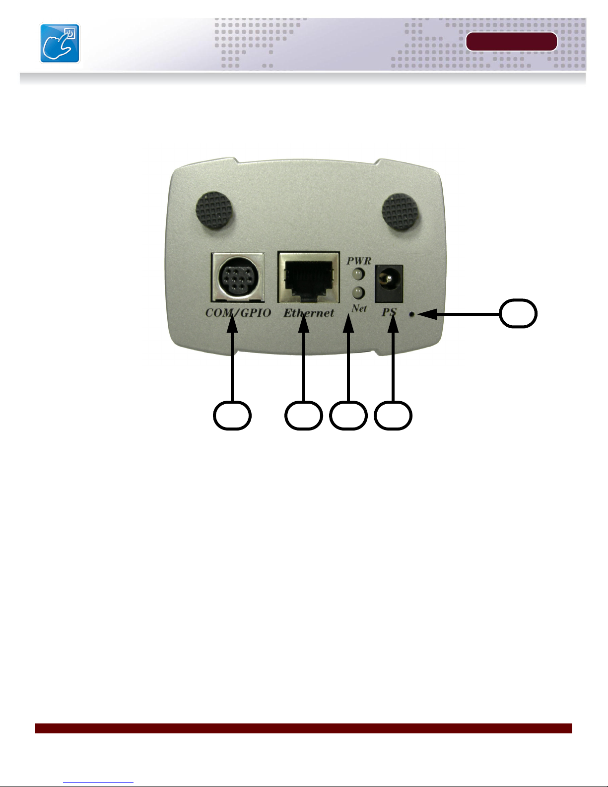
DNP5220E - Back
SECTION 2
5
1234
1. MINI-DIN/TERMINAL BLOCK PORT (Optional) - Connect the Mini-DIN Terminal Block cable
to the DIN connector Port. For more details on the available Terminal Block connections, please
see Appendix #2 in this manual.
2. ETHERNET PORT - Connect an Ethernet Cable to the RJ-45 Ethernet port to connect the
Camera to the network.
NOTE: This camera is PoE Enabled. If using PoE Equipment, the Ethernet Port will also power
the camera.
3. PWR / NET LED INDICATORS -
• The Red PWR LED indicates the Power state of the camera (ON/OFF).
• The Green NET LED indicates the Network state of the camera. The LED will blink when
network communication occurs.
4. POWER INPUT PORT - Provides power to the Camera when used with the provided Power
Adaptor.
5. FACTORY RESET PINHOLE - Resets the unit to Factory Defaults. See Appendix #6 for details.
12 HARDWARE MANUAL | Copyright © 2007 Digimerge Technologies Inc.
Page 13
SECTION 2
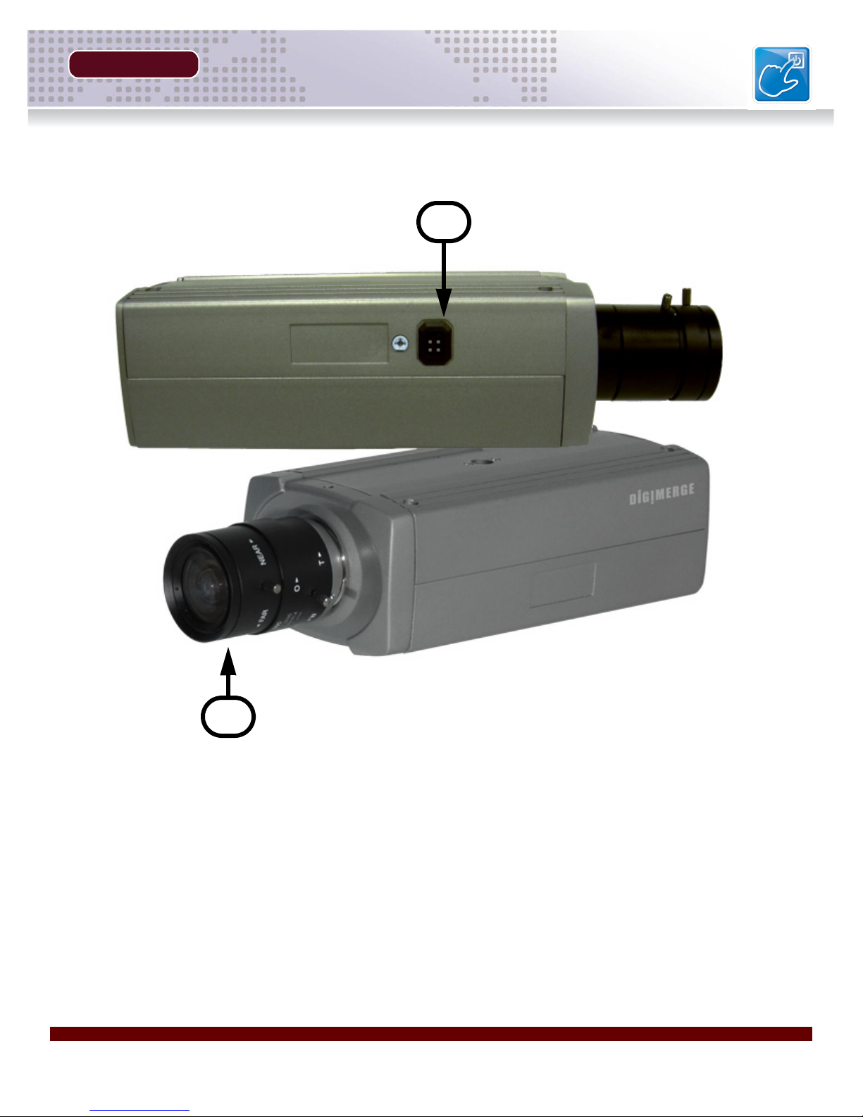
DNP5220E - Front / Side
DNP5220E - Front / Side
1
2
1. DC TYPE AUTO IRIS LENS CONNECTOR - This is the connection terminal for an auto iris lens
which does not have an internal circuit to control the Iris (DC Type).
2. LENS MOUNT (CS TYPE) - Supports a CS-Mount type lens (Not Included with this Camera).
NOTE: See Appendix #3 for Lens Mount Instructions.
Revision 1.0 13
Page 14

Page 15

SECTION 3
INSTALLATION
Installation Overview .......................... 16
Hardware Installation .......................... 16
Software Installation ........................... 17
Page 16

Installation Overview
Installation Overview
There are 3 mains steps required to perform a successful installation:
• Hardware installation
• Software installation
• Network configuration
SECTION 3
Hardware Installation
The Hardware installation consists of connecting
cables to the Camera including network (video), and
power cables. Other connections are optional.
1. Mounting Instructions: Run the cables to the
desired location and assemble the stand by
screwing together the different parts to get the
desired configuration. Securely mount the stand to
a wall or other surface using the provided screws.
Connect a lens with a CS Mount to the Camera
(See Appendix #3 for DC Auto Iris Lens installation).
Leave lens cap on until the end of the install.
Connect camera to the base (confirm that the
camera is the right side up) by screwing the bottom
onto the mounted stand.
2. Network: Connect the provided CAT-5 Ethernet
(Network) cable to the Camera network connector.
A longer CAT-5 cable can be used if desired (not
included).
NOTE: CAT-5 Ethernet Cabling has a maximum
effective range of 100m (330 ft.) depending on the
cable/switcher quality. For a longer run, a repeater
device may be required.
1
2
3. GPIO PTZ / Alarm (Optional): Connect the
mini-DIN Terminal Block cable to the Camera DIN
connector. This allows for additional options such
as connecting to an external monitor, controlling a
PTZ device and/or adding alarm inputs/outputs.
For more details on the available Terminal Block
connections, please see Appendix #2 in this
manual.
16 HARDWARE MANUAL | Copyright © 2007 Digimerge Technologies Inc.
3
Page 17

SECTION 3
Installation Overview
4. Power: Connect the supplied power adapter to the
power connector on the back of the Camera. If the
device will be powered using PoE (Power Over
Ethernet), the power will be provided to the Camera
via the Network cable. Please see Appendix #5 for
further details on this technology and use of PoE
Equipment. PoE accessories are not included.
Software Installation Overview
This IP device is provided with software applications to
make the most of the Device. This includes software for
installing, configuring and managing 1 or more
Digimerge IP Devices.
The following applications are included:
• DigiConsole (Included) - The Digiconsole
application loads from the CD included with your
package, and provides you with the following:
• Web links to various resources and documentation
• Discovery of all the Digimerge IP devices on the network
4
• Network configuration of IP Devices
• Installs DigiConsole and Surveillance application on your
local PC
• Warranty information and DDNS registration
• DigiViewer (Stored on the IP Device) - This
application resides on the IP Product, and is loaded
into the default browser when a connection to the
device is made.
• Apple Quicktime (Free Download) - This
application is used for displaying a live video stream
from the Device. Quicktime can be downloaded at
http://www.apple.com/quicktime
NOTE: Minimum Quicktime version installed should be 7.1.6. Microsoft Internet Explorer users
can use the Digimerge ActiveX Component (automatically installed when you view video) instead
of Quicktime to view the Video.
• Surveillance / Recording Software - Used for displaying and recording up to 32 channels.
Both MPEG-4 and MJPEG Formats are supported.
Revision 1.0 17
Page 18

Page 19

SECTION 4
NETWORK CONNECTIVITY
Network Connectivity Overview ..........20
Locating the MAC and IP Address ...... 21
Router Port Forwarding ...................... 22
Setting Up Your DDNS Account ...23~24
DigiViewer DDNS Setup .....................25
Remote Access with Internet Explorer 26
Internet Explorer Security Warnings ...26
Security Warnings - Program Installation27
Security Warnings - Windows Firewall 27
Page 20

Network Connectivity Overview
SECTION 4
Network Connectivity Overview
This camera is designed to be remotely controlled using your existing network and the provided
DigiViewer software (or a 3rd party compatible application - visit us on the web for an updated
compatible software list).
1. Connect the Camera to the Router or Switch using an Ethernet Cable, and power on the Camera.
NOTE: The Camera must be connected to the router prior to connecting the power to the
IP Device.
2. Locate the MAC and IP address of your Camera using the provided DigiConsole Setup Utility.
See next page for details.
3. Run the DigiConsole Software from the provided CD (optional installation to PC), and configure
the DigiViewer to allow DDNS connectivity. Refer to page 25 for details. See the DigiConsole
/ DigiViewer Software Guide (provided with this Camera) for installation requirements and
details on using the software.
INTERNET
CAMERA
ROUTER
(Not Included)
PC
(Not Included)
20 HARDWARE MANUAL | Copyright © 2007 Digimerge Technologies Inc.
Page 21

SECTION 4
Locating the MAC and IP Address
Locating the MAC and IP Address
Use the provided DigiConsole Setup Utility to locate your IP Address.
1. Run the DigiConsole application
from the CD provided with the
product. Select the Find Devices
button.
2. The DigiConsole automatically
locates all available Digimerge IP
devices on the network, and
displays a snapshot of the results.
Click on any available device to
display a snapshot image on the
right side screen display.
NOTE: You may need to press the Find
Devices button several times as some
devices may not respond immediately.If
you do not see a snapshot image, please
check that all cables running to the
Camera are connected properly. A
camera must be connected and
networked to view live images.
A username and password may be required when
connecting to the Camera (if configured on a previous
installation).
3. Record the MAC address. This information
is necessary for the DDNS Registration
process.
NOTE: The IP Devices must be on the same
local network as the PC for discovery and initial
setup. Once the device is properly configured, you may access it remotely over the internet.
Revision 1.0 21
Page 22

Router Port Forwarding
SECTION 4
Router Port Forwarding
In order to view the device remotely (over the Internet), follow the steps outlined on the following
5 pages to setup a free DDNS Remote Access account.
You will need to enable port forwarding on your Router to allow for external communications with
your Camera. The following ports will need to be forwarded to remotely connect to your Camera:
• Video Port 554
• Web Port 80
Computers, IP Cameras, and other devices inside your network can only communicate directly
with each other within the internal network. Computers and systems outside your network cannot
directly communicate with these devices. When a system on the internal network needs to send
or receive information from a system outside the network (i.e. from the Internet), the information
is sent to the Router.
NETWORK EXAMPLE
Router
External IP
216.13.154.34
Internet
(WAN)
When a computer on the Internet needs to send data to your internal network, it sends this data
to the external IP address of the Router. The Router then needs to decide where this data is to
be sent to. This is where setting up Port Forwarding becomes important.
Port Forwarding tells the router which device on the internal network to send the data to. When
you set up port forwarding on your Router, it takes the data from the external IP address:port
number and sends that data to an internal IP address:port number (i.e Router External IP
216.13.154.34:554 to IP Camera Internal IP 192.168.0.3:554).
Router
Internal IP
192.168.0.1
Internal Network
(LAN)
Computer
Internal IP
192.168.0.101
Camera
Internal IP
192.168.0.102
To locate your external IP address, visit http://www.whatismyip.com
NOTE: If using multiple IP Devices on the same network, each device will need to be assigned to
a different remote access port.
22 HARDWARE MANUAL | Copyright © 2007 Digimerge Technologies Inc.
Page 23

SECTION 4
Setting Up Your DDNS Account
Setting Up Your DDNS Account
Digimerge offers a free DDNS server for use with your IP Camera. A DDNS account allows you
to set up a web site address that points back to your Local Network. The following outlines how to
set up your free DNS account.
1. Navigate to http://DDNS.digimerge.net
2. Select the Create Account option from the list on the left
side of the screen.
3. Complete the Account Information fields with your personal information
Revision 1.0 23
Page 24

Setting Up Your DDNS Account
4. Complete the System Information fields as follows:
PRODUCT LICENSE SECTION:
• Product Code: Select your product model from the Product
Code drop down menu
• <Product Code> - <MAC Address>: Locate the MAC address
of your System by pressing the Info button on the Remote (or
from the menu).
URL REQUEST SECTION:
• URL Request: Choose a URL for your DDNS connection (i.e.
your name, your company or business name, or anything of
your choice.)
5. Click the Create New Account link at the bottom of the form to submit your request.
SECTION 4
6. Your Account information will be sent to you at the E-mail Address you used in Step 3.
Domain name:
User name:
Password:
You will need this information for remote access to your System. Record YOUR
below:
Domain Name: _______________________________________________
User Name: _________________________________________________
Password: __________________________________________________
NOTE: The information sent to you in E-mail is CASE SENSITIVE. It is important when set-
ting up your DDNS information on your device.
tomsmith
tomsmith1
1234
information
24 HARDWARE MANUAL | Copyright © 2007 Digimerge Technologies Inc.
Page 25

SECTION 4
DigiViewer DDNS Setup
DigiViewer DDNS Setup
Use the information received in email from the DDNS setup (previous page) to configure the IP
Device for remote connection (using the DigiViewer application).
1. Right Click on the Camera in the DigiConsole
application. Select the Open Device in
Browser option.
2. The DigiViewer application will load in the default Web Browser.
C
B
A
A. Click on the SETTINGS link
B. Click on the NETWORK SERVICES link.
C. Enter the DDNS information received in the DDNS Confirmation Email:
z Check ‘Enable Digimerge Dynamic DNS Service
z Enter the DDNS Domain name you chose during the DDNS Registration process
z Enter the Account Name you setup during the DDNS Registration Process.
The information is automatically saved once you switch to any other screen within the
DigiViewer. DO NOT close the window before changing screens, or the setup will be lost.
Revision 1.0 25
Page 26

Remote Access with Internet Explorer
SECTION 4
Remote Access with Internet Explorer
Open Internet Explorer, and enter the Local IP (i.e. http://192.168.0.104 if inside the Local
Network), the Remote IP (i.e. http://72.154.89.164) or DDNS Address (http://
myurl.digimerge.net) for the remote IP Device.
http://myurl.digimerge.net
Internet Explorer Security Warnings
Several security warnings may appear (based on your Internet Explorer settings). The
applications requesting security clearance are required to view live video on your system.
• Right Click on the Yellow Security Bar, and select ‘Install’
26 HARDWARE MANUAL | Copyright © 2007 Digimerge Technologies Inc.
Page 27

SECTION 4
Remote Access with Internet Explorer
Internet Explorer Security Warnings - Program Installation
The DigiConsole and DigiViewer may require additional application information to be installed to
your PC.
• Click the Install button to allow the ActiveX controls to be setup on the PC.
Internet Explorer Security Warnings - Windows Firewall
The Digimerge IP Devices require connectivity across the network, and may be flagged by the
Windows Firewall when a connection to your PC is made.
• Select UNBLOCK to use the DigiConsole and Apple Quicktime applications.
Revision 1.0 27
Page 28

Page 29

APPENDICES
Appendix #1 - Camera Specifications
Appendix #2 - COM / GPIO Terminal Block
Appendix #3 - DC Auto Iris Lens Installation
Appendix #4 - Changing the Camera
Appendix #5 - Power Over Ethernet (PoE)
Appendix #6 - Hardware Reset
Other Digimerge IP Products
Digimerge Limited Warranty
Page 30

Appendix #1 - Camera Specifications
Appendix #1 - Camera Specifications
Hardware
Image Sensor 1/3” Sony Super HAD CCD
Horizontal Resolution: 520 TV Lines
0.15 LUX (F1.2)
SECTION 5
Monitoring
Connectors
Lens • Standard package: Accepts CS mount type lenses
Image Compression • MPEG-4 Simple Profile (SP); JPEG, MJPEG
CCD Adjustment • White Balance (WB/AWB): Auto
Watchdog Chipset; monitors system voltage
tolerance and abnormal program execution
1 x x RJ-45 Connector for Ethernet (with Built-in Power
Over Ethernet IEEE 802.3af).
1 x Mini-DIN for RS-485/RS-232/GPIO/Video Out.
• RS-485: For external Pan/Tilt (PT) device
• RS-232: For Console connection
• GPIO: For one fully opto-isolated alarm input and
one relay output
• Video Out: For connecting to a CCTV monitor,
DVR, etc.
1 x Internal Microphone
1 x 12V DC Jack
1 x DC-Iris Power Connector
2 x LEDs to indicate network and power/system status.
• Supports Direct drive lenses: Built-in VR for DC
level adjustment.
• gain Control (GC/AGC): On/Off
• Electronic Shutter (ES/AES): On/Off
Resolutions
Video Adjustment • Brightness, Contrast, Hue, Saturation, Frame
Image Compression 16K~4M bits/sec (CBR/VBR configurable)
30 HARDWARE MANUAL | Copyright © 2007 Digimerge Technologies Inc.
• Full D1 (4CIF): NTSC = 720x480
• CIF: NTSC = 352x240
• QCIF: NTSC = 176x112
Rate, Bit Rate (Constant Bit Rate (CBR), Variable
Bit Rate (VBER) w/quality levels), Frame
Sequence (I-Frame, I-Frame/P-Frame), Group of
Pictures (GOP) size (Advanced Features).
Page 31

SECTION 5
Network
Appendix #1 - Camera Specifications
Network
Management
Event Management
Installation
Firmware Upgrade
Viewers / Supported
Browsers
Security
Recording
Network Interface:
• 10/100 Base-T Ethernet
Protocols:
• TCP (UDP)/IP, IMCP, HTTP, FTP, SMTP, DHCP,
NTP, DNS, DDNS, RTSP, RTP/TCP (UDP).
Triggers: Motion Detection
Manual Recording
DigiConsole Utility (PC)
Remote upgrade via network
• Microsoft Internet Explorer, Firefox, Opera and
Apple Safari
• Apple Quicktime or compatible RTSP Client
Password Option
FTP to storage, AVI Format
Other
Operating Temperature 40°F ~ 122°F
(5°C ~ 50°C)
Operating Humidity 20%~80% RHG
Input Voltage DC 12V, 1A
Power Consumption < 8 Watts
Unit Dimensions
(W x D x H)
Unit Net Weight 0.53 kg / 1.2 lbs. (Body Only)
Gross Dimensions (inc.
packaging - W x D x H)
Gross Weight (including
packaging & accessories)
Software Provided • DigiConsole Setup Utility
3.0” x 6.2” x 2.2” (Body Only)
75mm x 153mm x 53mm
12.4” x 11.2” 3.3”
310mm x 280mm x 82mm
1.25 kg / 2.8lbs.
• DigiViewer Web Browser Interface
• DigiClient 16 Channel Viewing / Recording /
Playback / Remote Access Application.
Revision 1.0 31
Page 32

Appendix #2 - COM / GPIO Terminal Block /
SECTION 5
Appendix #2 - COM / GPIO Terminal Block / Female BNC
The GPIO & COM provides a control signal input and output, which includes:
• One GPIO input
• One GPIO output (Relay connection)
• One RS-485 port multiplex with COM port.
The GPIO & COM port provides a connection for PTZ devices or an external
console to control the device. A motion detection or sensor unit can also be
used to send a signal to begin camera recording (when configured in the
DigiViewer Menu settings or compatible 3rd party software).
GPIO Pin Out Configuration
1. GPIN - Input high when opening
the connection; input low when
sinking more than 10mA or
shorting to pin 5 (GND).
2. RXD - COM Port Receive Data.
3. TXD - COM Port Transmit Data.
4. RS485 (A) - Connect an external
PTZ or Alarm device. For PTZ
control both pins 4 & 8 must be
used.
5. GND (System Ground) - The
System Ground is also
connected to the chassis as
frame ground.
6. GPOUT (Automatic Relay) -
When the DigiViewer is
configured to use the GPIN or
Motion detection to trigger alarm
devices, the “Relay Out” must be
turned on.
7. GPOUT (Automatic Relay) - When the DigiViewer is configured to use the GPIN or Motion
detection to trigger alarm devices, the “Relay Out” must be turned on.
8. RS485 (B) - Connect an external PTZ or Alarm device. For PTZ control both pins 4 & 8 must
be used.
9. BNC Type (Video Out) - Use the GPIO cable provided with this camera to directly output the
video to a monitor.
32 HARDWARE MANUAL | Copyright © 2007 Digimerge Technologies Inc.
Page 33

SECTION 5
Appendix #2 - COM / GPIO Terminal Block /
Features and Specifications of the GPIO Solid State Relay
• Normally Open, Single Pole Single Throw
• Control 350VAC or DC Voltage
• Switch 130mA Loads
• LED control Current (5mA)
• Low ON-Resistance
• dv/dt >500 V/ms
• Isolation Test Voltage, 3750VACrms
Absolute Maximum Ratings (TA=25°C):
Emitter (Input)
Reverse Voltage:
Continuous Forward Current:
Peak Forward Current:
Power Dissipation:
Derate Linearly from:
General Characteristics
Isolation Test Voltage:
Isolation Resistance:
Total Power Dissipation:
Derate Linerly from:
Storage Temperature Range:
Operating Temperature Range:
Junction Temperature:
Soldering Temperature:
5.0V
50mA
1A
100mW
25°C: 1.3mW/°C
3750 VAC rms
Vio=500V; TA=25°C,
550mW
25°C: 2.5mW/°C
-40°C ~ 125°C
-30°C ~ 85°C
100°C
2mm from case, 10 sec.260°C
Emitter (Input)
Output Breakdown Voltage:
Continuous Load Current:
Power Dissipation:
≥1010Ω
± 350V
± 130mA
500mW
Revision 1.0 33
Page 34

Appendix #3 - DC Auto Iris Lens Installation
SECTION 5
Appendix #3 - DC Auto Iris Lens Installation
Lenses for this IP product are sold separately. DC Auto Iris and CS-Mount lenses are compatible
with this product. Please note that:
• Use of an auto iris lens is recommended to achieve the best results for operating this product
effectively under a wide range of lighting conditions. Auto Iris Lenses are perfect for locations,
where light is constantly changing, such as outside parking lot, and building entrances. Auto
Iris Lenses are powered through cameras power supply. The iris for these lenses automatically
opens and closes according to the changes of the light conditions. If the light level is low, the
lens iris opens up to allow enough light for optimum picture quality, and when the light level
is high, it closes the iris so that incoming light does not overwhelm the camera and blur out
the picture.
• Please keep the lens clean.
• Any foreign objects and finger marks on the lens will cause inferior image quality in low light
level conditions.
1. Peel off about 8mm of the outer
plastic wire cover (of the auto iris lens
cable).
2. Peel off about 2mm of the outer skin
of the insulated conductor inside the
lens cable.
3. Remove the cover of the DC Auto Iris
lens connection plug, and solder the
lens cable to the connector pin in the
plug.
34 HARDWARE MANUAL | Copyright © 2007 Digimerge Technologies Inc.
Page 35

SECTION 5
4. Replace the DC Auto Iris lens connection plug cover, and remove the lens protection cap. Attach
the auto iris lens to the camera by screwing it in clockwise.
5. Please insert the connection plug (connected to the auto iris lens cable) into the auto lens
connector port located on the side of the IP Camera.
Appendix #3 - DC Auto Iris Lens Installation
AES Lens Cable - Pin Configuration
Revision 1.0 35
Page 36

Appendix #4 - Changing the Camera Network
SECTION 5
Appendix #4 - Changing the Camera Network Settings
The network settings on the camera can be manually set using the DigiConsole application:
Menu - Edit Network Parameters
The Edit Network Parameters option allows the user to manually set the Network Device options
(if desired).
NOTE: The Network Settings will
automatically be assigned by the Network
router (when the device is connected to the
Network). This information can be
changed, however incorrect changes to
these settings will prevent access to the
device, and a Hardware Reset will be
required.
1. IP Address & Port -The IP address
and port assigned to the IP Device.
2. Subnet Mask - The Subnet Mask
assigned by the Network Router.
3. Gateway Address - The Gateway
Address is the address of the Router.
This information is automatically
assigned by the Network Router, and
is necessary for communication on
the Network.
4. Domain Name Server 1 - The IP
address of the Domain Server. This
information is necessary when using
the DDNS Service.
5. Domain Name Server 2 - A backup
IP address for the Domain Server.
This information is necessary when
using the DDNS Service
1
2
3
4
5
36 HARDWARE MANUAL | Copyright © 2007 Digimerge Technologies Inc.
Page 37

SECTION 5
Appendix #5 - Power Over Ethernet (PoE)
Appendix #5 - Power Over Ethernet (PoE)
Power over Ethernet, also known as PoE, is a technology for carrying power along with data on
standard CAT5 network cables, allowing devices to be powered via their network ports. It is supported by some devices directly (e.g. 802.3af compliant or “PoE Enabled” devices) while other
devices require PoE accessories, such as PoE Endspans, PoE Midspans, power injectors and/or
active splitters, in order to make use of the technology.
• PoE Endspan – PoE enabled Ethernet switch
• PoE Midspan - PoE multi port injector for use with non-PoE Ethernet switches
• PoE Injectors – Adapter that injects Power into an Ethernet cable. Can be used in combination
with an active splitter (for connecting to non-PoE devices) or used on its own (for connecting
to PoE enabled devices)
• Active Splitter – An adapter that splits the Date and Power transmissions over a single
Ethernet cable (PoE) into a separate Date (using RJ45 connector) and power stream (using
power barrel connector) for use strictly with non-PoE devices
NOTE: PoE allows devices to be powered with a power rating of up to 12.9W. Devices that consume more then 12.9W but less than 39W require use of High Power PoE (IEEE-802.3at)
devices. High Power PoE devices like the 8000 series from Microsemi are readily available. An
example of an IP camera that would require High Power PoE to power it up would be PTZ Speed
Dome cameras which consume a lot of power.
A detailed description of the 802.3af standard is available in IEEE publication SS95312
(http://standards.ieee.org/getieee802/download/802.3af-2003.pdf).
The main benefits of PoE technology are:
Lower Costs
• Eliminate the need to run A/C power wires
• Utilize existing IT infrastructure investments
More Flexible
• Locate device where it truly needs to be located (Not constrained by the location of an AC outlet)
Centralize vs. Localize Power Source
• Allow use of a centralized UPS (Uninterruptible power supply) to guarantee power to the
device even during a power failure
Revision 1.0 37
Page 38

Appendix #5 - Power Over Ethernet (PoE)
SECTION 5
Manageability
• PoE devices that are Simple Network Management Protocol (SNMP) manageable can be
remotely monitored and controlled
The main benefits of PoE Midspan use over PoE Endspan use are:
• Improve ROI on current installations
• Minimize capital expenditure
z Keep the existing Switches
• Lower purchase price
z 30% less than Enterprise PoE switch
• Easy and simple to install
z Lower installation costs - 20% less than Enterprise PoE switch
z Enable higher productivity - Negligible downtime
• PoE investment is protected
z Switch technology changes
z Why pay for PoE every time you upgrade your switch?
• Gain flexibility to power also pre-standard terminals
Examples of PoE installations using…
PoE Endspan
Endspan
Endspan
PoE Midspan
Non-PoE Ethernet Switch
Non-PoE Ethernet Switch
PoE Injector
Non-PoE Ethernet Switch
⇒ IP camera (PoE enabled)
⇒ Active Splitter ⇒ IP Camera (non-PoE)
⇒ Midspan ⇒ IP Camera (PoE enabled)
⇒ Midspan ⇒ Active Splitter ⇒ IP Camera (non-PoE)
⇒ PoE Injector ⇒ IP Camera (PoE enabled)
Poe Injector + Splitter
Non-PoE Ethernet Switch
⇒ PoE Injector ⇒ Active Splitter ⇒ IP Camera (non-PoE)
Digimerge IP Devices are certified for use with Microsemi PoE hardware solutions. Visit
www.microsemi.com/PowerDsine
38 HARDWARE MANUAL | Copyright © 2007 Digimerge Technologies Inc.
for details on all available PoE hardware solutions.
Page 39

SECTION 5
Appendix #6 - Hardware Reset
Appendix #6 - Hardware Reset
There are 2 ways to reset the IP Device:
DigiViewer Reset
To restore Factory Defaults from the DigiViewer Web Browser Interface (Note: This only works if
the network browser access to the device is operational):
• Log into the video device as
administrator using the admin
username and password. This
applies only if users are set up in
the device. If not then just open
the web page.
• Select the 'Settings' page in the
DigiViewer. Click on the
'Advanced Settings' link. Click on
the 'Factory Settings: Restore'.
• Close the browser. To access the
device again refresh the browser
after 30 seconds.
NOTE: This will not reset Networking and
Account Settings.
Hardware Reset
To Restore Factory Defaults from the Hardware:
• Unplug the power jack to turn off the device. Uncurl a paperclip about 2cm long, insert it
into the “Factory Default Hole” and push
the button behind the hole. Hold this and
do not release.
• Plug in the power jack to turn on the device.
Observe the Power LED - when power on
the LED is red, wait for a few seconds.
The LED will change to orange, flash four
times and then change back to red. At this
moment release the factory default button
and the device will be restored to factory
default settings.
NOTE: Allow time for the camera to restart
(approximately 1 minute).
Revision 1.0 39
Page 40

Digimerge IP Products
Digimerge IP Products
SECTION 5
40 HARDWARE MANUAL | Copyright © 2007 Digimerge Technologies Inc.
Page 41

Digimerge Network Video Servers - Limited 3 Year
Hardware Warranty
Warranty: Subject to the exclusions, limitations and exceptions, Digimerge warrants to the initial end-user purchaser
that this hardware product is free from manufacturing defects under normal use for a period of three (3) years from the
date of purchase.
Exceptions to the above warranty are:
• Camera components including, but not limited to, moving parts, motors, fans, heaters, hard drives, removable
flash memory, camera image sensors, DC iris and lens assemblies and Pan Tilt Zoom (PTZ) related components
including electrical slip ring contacts, and pan/tilt/lens motors. These are warranted for a one (1) year period.
• PTZ related components:
Software & Consumables: All software, accompanying documentation and consumables (including but not limited to
fuses and batteries) provided with or as part of the product are furnished AS IS, and are excluded from warranty coverage. Digimerge is not obligated to provide the end-user with a substitute product during the warranty period or at any
time.
NOTE: Products are subject to continuous improvement. DIGIMERGE Technologies Inc. and its subsidiaries reserve
the right to modify product design, specifications and prices, without notice and without incurring any obligation. Software and firmware are subject to updates from time to time.
For valid warranty claims made during the warranty period, upon proper proof of purchase (which is defined as a “valid
form of a bill of sale or receipt from an authorized retailer or distributor showing the original date of purchase”), defective
products will, at the sole discretion of Digimerge, be repaired or replaced with equal or better product in terms of hardware features without charge if all the conditions set forth in this document are met. Any products repaired or replaced
within the warranty period, shall be warranted by Digimerge to the initial end-user purchaser for 90 days from the return
shipment date, or the remainder of the warranty term, whichever is longer. Repairs are warranted for 90 days outside
the original warranty period. Products and parts, at Digimerge's sole discretion, may be replaced with new or refurbished
items, and the products and parts replaced become the property of Digimerge. The customer is responsible for all shipping costs associated with the return of the defective products for warranty service to Digimerge warranty/repair facilities. Products will be returned to the end-user freight prepaid.
Exclusions and Limitations: Any of the following will void this warranty:
1. Installation or use of the product other than strictly in accordance with the instructions contained in the
product's instruction manual;
2. If the product is subjected to operating conditions (including atmospheric, moisture and humidity conditions)
outside of the acceptable conditions specified in the product's instruction manual;
3. If the product is subjected to misuse (not adhering to instructions supplied with the product), negligence,
modification (of hardware, firmware or software) or abuse;
4. If the product is subjected to electrical short circuits or transients, accident, fire, flood or Acts of God;
5. Adjustment, maintenance or repair of the product other than in accordance with Digimerge approved
procedures; and
6. Use of replacement parts other than those specified by Digimerge.
7. If the products original identification (trademark, serial number, model number) markings have been removed,
defaced or altered
z If the PTZ Camera is used in continuous motion applications (50 - 100% duty cycle - i.e. guard tour or
sequence presets), the warranty period for the entire camera and related hardware components will be
limited to six (6) months from the date of the end user original purchase
DIGIMERGE MAKES NO CLAIMS OR WARRANTIES OF ANY KIND WHATSOEVER REGARDING THE PRODUCT'S
ABILITY OR EFFECTIVENESS IN PREVENTING OR REDUCING THE RISK OF, OR DAMAGES RESULTING FROM,
LOSS OR THEFT OF PROPERTY OR PERSONAL INJURY. THIS LIMITED WARRANTY IS IN LIEU OF ALL OTHER
WARRANTIES, EXPRESS OR IMPLIED, INCLUDING, BUT NOT LIMITED TO, ANY IMPLIED WARRANTY OF MERCHANTABILITY OR FITNESS FOR A PARTICULAR USE OR PURPOSE. REPAIR OR REPLACEMENT AS PROVIDED UNDER THIS LIMITED WARRANTY IS THE EXCLUSIVE REMEDY OF THE PURCHASER. DIGIMERGE SHALL
IN NO EVENT BE LIABLE FOR ANY SPECIAL, INDIRECT, INCIDENTAL, PUNITIVE, OR CONSEQUENTIAL DAMAGES OF ANY KIND OR CHARACTER, INCLUDING, WITHOUT LIMITATION, PERSONAL INJURY, LOSS OF REVENUE OR PROFITS, FAILURE TO REALIZE SAVINGS OR OTHER BENEFITS, OR CLAIMS AGAINST THE
PURCHASER BY ANY THIRD PERSON, EVEN IF DIGIMERGE HAS BEEN ADVISED OF THE POSSIBILITY OF
SUCH DAMAGES.
Page 42

Digimerge Network Video Servers - Limited 3 Year
Hardware Warranty (cont.)
No claims or statements regarding the product, whether written or verbal, by salespeople, retailers, dealers or distributors, that are not contained in this limited warranty or in the owner's manual are authorized by Digimerge and do not
modify or expand this warranty. Some countries, states, or provinces do not allow the exclusion or limitation of implied
warranties or the limitation of incidental or consequential damages for certain products supplied to consumers or the
limitation of liability for personal injury. To the extent that such restrictions on limitations apply to the products, the above
limitations and exclusions may be limited in their application. In that case, when the implied warranties are not allowed
to be excluded in their entirety, they will be limited to the duration of the applicable written warranty, and if damages may
not be limited then the above limitations on damages apply, but only to the greatest extent permitted by local law.
Warranty and Non-Warranty Service:
Warranty service can be received by contacting your Digimerge dealer (during the warranty period). The dealer is required to first contact Digimerge Technical Support for assistance. In the event the problem cannot be resolved over the
phone or via email, Digimerge will advise to return the product, at customer's expense, for repair or replacement. Upon
receipt of the defective camera, Digimerge will send a repaired or replacement camera at Digimerge's expense to the
customer. Dealer should send product to:
In United States:
Digimerge Returns
C/O Russell A. Farrow
15 Lawrence Bell Drive
Amherst, NY
14221
In Canada:
Digimerge Technologies Inc.,
Attention: Repair Department,
300 Alden Rd.,
Markham, Ontario, Canada,
L3R 4C1
Out of warranty service: Please visit our web site (www.digimerge.com
authorized service centers.
) for the name and location of the Digimerge
Page 43

It’s all on the web
Product Information
User Manuals
Quick Start Guides
Specification Sheets
Software Upgrades
Firmware Upgrades
VISIT
www.digimerge.com
Digimerge Technologies Inc.
www.digimerge.com
Page 44

 Loading...