

Page 1
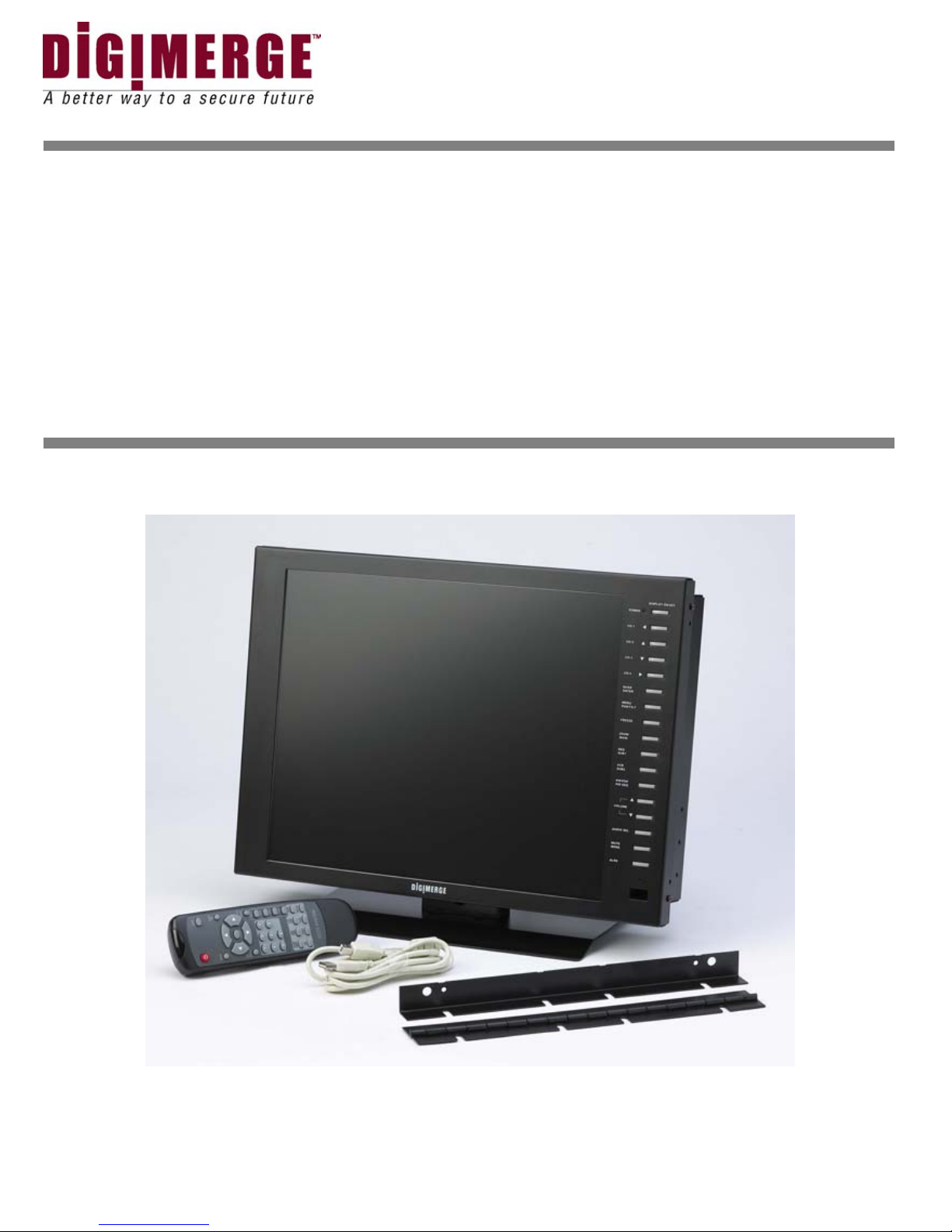
17” TFT LCD Monitor
With Integrated Quad Processor
Model: DM17TQ
Installation / User Manual
Page 2
CAUTION
RISK OF ELECTRIC SHOCK. DO NOT OPEN.
CAUTION: TO REDUCE THE RISK OF ELECTRIC SHOCK, DO NOT
REMOVE COVER (OR BACK). NO USER-SERVICEABLE PARTS
INSIDE. REFER SERVICING TO QUALIFIED SERVICE PERSONNEL.
WARNING : TO PREVENT FIRE OR SHOCK HAZARD, DO NOT
EXPOSE THE UNIT TO RAIN OR MOISTURE
The lightning flash with arrowhead symbol, within an equilateral
triangle, is intended to alert the user to the presence of un-insulated
"dangerous voltage" within the product's enclosure that may be of
sufficient magnitude to constitute a risk of electric shock to persons.
The exclamation point within an equilateral triangle is intended to
alert the user to the presence of important operating and
!
maintenance (servicing) instructions in the literature accompanying
the appliance.
!
This equipment has been tested and found to comply with the limits For a Class
B digital device, pursuant to Part 15 of the FCC Rules. These limits are designed
to provide reasonable protection against harmful interference in a residential
installation. This equipment generates, uses and can radiate radio frequency
energy and, if not installed and used in accordance with the instruction, may
cause harmful interference to radio communications. However, there is no
guarantee that interference will not occur in a particular installation. If this
equipment does cause harmful interference to radio or television reception,
(which can be determined by turning the equipment off and on), the user is
encouraged to try to correct the interference by one or more of the following
measures:
• Increase the separation between the equipment and the camera and/or
monitor.
• Connect the equipment into an outlet on a circuit different from that to which
the monitor is connected.
Consult the dealer or an experienced radio or television technician for help.
-i-
-i-
Page 3

NOTE
This equipment has been certified and found to comply with the limits regulated by
FCC, EMC and LVD. Therefore, it is designed to provide reasonable protection
against interference and will not cause interference with other appliance usage.
However, it is imperative that user follows this manual's guidelines to avoid improper
usage which may result in damage to the unit, electrical shock and fire hazard or
injury.
In order to improve the feature functions and quality of this product, the specifications
are subject to change without notice from time to time.
FCC CLASS B NOTICE
Note:
This equipment has been tested and found to comply with the limits For a Class B
digital device, pursuant to Part 15 of the FCC Rules. These limits are designed to
provide reasonable protection against harmful interference in a residential
installation. This equipment generates, Uses and can radiate radio frequency energy
and, if not installed and used in accordance with the instruction, may cause harmful
interference to radio communications. However, there is no guarantee that
interference will not occur in a particular installation. If this equipment does cause
harmful interference to radio or television reception, (which can be determined by
turning the equipment off and on), the user is encouraged to try to correct the
interference by one or more of the following measures:
• Reorient or relocate the receiving antenna.
• Increase the separation between the equipment and receiver.
• Connect the equipment into an outlet on a circuit different from that to which the
receiver is connected.
• Consult the dealer or an experienced radio or television technician for help.
-ii-
Page 4

CONTENTS:
1. GENERAL PRECAUTIONS --------------------------------------------------------------------- 2
2. INTRODUCTION----------------- ------------------------------------------------------------------ 3
3. SYSTEM --------------------------------------------------------------------------------------------- 4
4. CONNECTING THE TFT STAND ------------------------------------------------------------- 4
5. MONITOR CONTROLS - FRONT PANEL -------------------------------------------------- 5
6. MAIN MENU CONTROL ------------------------------------------------------------------------ 8
7. PAN/TILT ZOOM ----------------------------------------------------------------------------------- 11
8. MONITOR CONNECTIONS - BACK PANEL----------------------------------------------- 12
9. SIDE PANEL --------------------------------------------------------------------------------------- 13
10. REMOTE CONTROL----------------------------------------------------------------------------- 14
11. TROUBLE SHOOTING ------------------------------------------------------------------------ 15
12. TECHNICAL SPECIFICATIONS ------------------------------------------------------------ 16
13. OPTIONAL ACCESSORIES ----------------------------------------------------------------- 18
14. APPENDIX A – CONNECTION EXAMPLES---------------------------------------------- 17
15. CARE AND MAINTENANCE ------------------------------------------------------------------ 18
-1-
Page 5

GENERAL PRECAUTIONS:
1. Read Instructions
All of the safety and operating instructions should
be read and understood before the product is used.
2. Retain Instructions
The safety and operating instructions should be
retained for future reference.
3. Heed Warnings
All warnings on the product and the instruction
manual should be followed.
4. Follow Instructions
All operating and use instructions should be followed
for optimal performance
5. Cleaning
Disconnect this video product from the power supply
before cleaning. Do not use liquid cleaners or aerosol
cleaners. Use a damp cloth for cleaning.
6. Attachments
Do not use attachments not recommended by the
video product manufacturer as they may cause
hazards.
7. Water and Moisture
Do not use this product near water - for example,
near a bathtub, wash bowl, kitchen sink, wet
basement, or near a swimming pool.
8. Accessories
Use this product only with a stand, tripod, bracket or
table recommended by the manufacturer or sold
with the product. Any mounting of the product
should follow the manufacturer’s instructions.
9. Ventilation
This product should never be placed near or over a
Radiator or heat register. This product should not be
placed in a built-in installation, such as a book case
or rack, unless proper ventilation is provided or the
Manufacturer’s instructions have been adhered to.
10. Power Source
This product should be operated from the type of
Power source indicated by the marking label. If you
are not sure of the type of power supply to your
location, consult your product dealer or your local
Power company
11. Power Cord Protection
Power supply cords should not be routed so that
They are likely to be walked on or pinched by items
placed on or near them
12. Lightning
For added protection, unplug this product from its
outlet during a lightning storm. This will prevent
damage to the video product due to lightning and
power surges
13. Overloading
To avoid the risk of fire and electric shock, do not
plug this product into an over-loaded power supply.
14. Object and Liquid Entry
Never push objects into the openings of this product
as they may touch dangerous voltage points that
may result in fire or electric shock. Never spill a liquid
of any kind on this product.
15. Servicing
Do not attempt to service this product yourself as
opening or removing covers may expose you to
voltage or other hazards. Refer all servicing to
qualified service personnel
16. Damage Requiring Service
Disconnect this product from the power supply
and refer servicing to qualified service
personnel under the following conditions:
a. When the power supply cord or plug is damaged
b. If objects have fallen into the product
c. If the product has been exposed to rain or liquids
d. If the product does not operate normally by
following the instruction manual. Adjust only
the controls that are covered in the instruction
manual as an improper adjustment may result
in damage and will often require extensive work
by a qualified service technician to restore
the product to its normal operation
e. If the product has been dropped or the cabinet
has been damaged
f. When the product displays a distinct change in
performance - this indicates a need for service
17. Replacement Parts
When replacement parts are required, be sure the
technician uses replacement parts specified by
the manufacturer. Unauthorized substitutions may
result in fire, electric shock, or other hazards.
18. Safety Check
Upon completion of any service to this product
ask the service technician to perform safety
checks to determine that the product is in
proper working condition.
19. Grounding or Polarization
This product is equipped with a three-wire
grounding-type plug, a plug having a third
(grounding) pin and will only fit into a
grounding-type power outlet. This is a safety
feature. If you are unable to insert the plug
into the outlet, contact your electrician to
replace your obsolete outlet. Do not defeat the
safety purpose of the grounding-type plug.
20. Power Lines
An outside antenna system should not be
located in the vicinity of overhead power lines
or other electric light or power circuits, or where
it can fall into such power lines or circuits.
When installing an outside antenna system,
extreme care should be taken to keep from
touching such power lines or circuits as contact
with them might be fatal.
21. Wall or Ceiling Mounting
The product should be mounted to a wall or ceiling
only as recommended by the manufacturer.
22. Heat
The product should be situated away from heat
such as radiators, hear registers, stoves, or other
products (including amplifiers) that produce heat.
Page 6

Introduction
The
Monitor Features:
• Display a full, flat 17” Viewable area
• View up to 4 camera locations in real time
• High Resolution Monitor delivers superior image clarity
• Ultra high brightness and an excellent contrast ratio for sharp true to life image;
• Pan/ Tilt / Zoom capable (Pelco D Protocol);
• Metal cabinet with 4 camera inputs (4 BNC and 4 audio RCA)
• 2 way audio
• Single or Dual PIP viewing options – main and PIP channels
• Selectable POP viewing options
• Selectable still frame in quad or full screen
• Two times zoom
• Motion Sensing Alarm Function
• Video loss detection warning
• On screen viewing: date*time*camera
• Remote control or main panel operation
• ON/OFF standby switch enables monitor screen to be turned off while recording
• Multi-voltage system 100 – 240Volts
-3-
Page 7
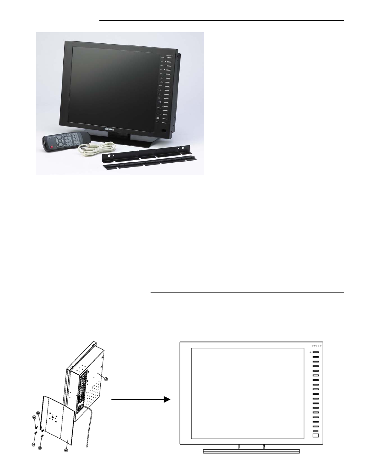
SYSTEM INCLUDES:
•17” TFT COLOR QUAD MONITOR
•Remote Control
•Desk Stand
•Rack Mount Ears
•USB Cable
•Owners Manual
CONNECTING THE TFT STAND:
Use the supplied screws to connect the stand for the TFT monitor to the base.
Brackets and screws are also included for Rack Mounting applications. Please refer to
Appendix F for a diagram illustrating Rack Mounting.
-4-
Page 8

CONTROL - FRONT PANEL:
POWER
CH1/5
(LEFT)
CH2/6
(UP)
CH3/7
(DOWN)
CH4/8
(RIGHT)
QUAD
QUAD
ENTER
PAGE
ENTER
MENU
(PAN/TILT)
FREEZE
ALARM
ALRS
ZOOM
MAIN
SEQ
SUB1
VCR
SUB2
PIP/POP
PIP-SEQ
VOLUME
AUDIO SEL
DISPLAY ON / OFF
◄
FOCUS NEAR
▲
FOCUS FAR
▼
ZOOM WIDE
►
ZOOM TELE
ZOOM/FOCUS
1
2
3
4
5
6
7
8
9
10
1. Standby Switch - This switch will turn the monitor ON/OFF.
A red LED indicator light is ON when the monitor is in
Standby mode. Press the button to turn the power ON. Allow
for 5-7 seconds for the picture to appear.
Note: The master power switch, which controls the monitor
is located on the side of the unit.
Note: To provide longer life to the TFT monitor, turn the
Standby switch OFF when not in use. The system will
continue to record images to VCR.
2. Channel 1 – Channel 4 - These buttons perform the
following functions:
a) Displays a picture in Full Screen.
If you are in the Quad mode, select the Channel 1
button and hold for 2-3 seconds to view Camera 1 in Full
Screen. To view other camera locations, press the Ch 2,
Ch 3, Ch 4 buttons.
b) Freezes a specific camera.
You have the option to freeze images in Full or Quad
screen mode.
In Quad Screen mode: press a channel button to freeze
this channel in the Quad screen; press again to unfreeze;
In Full Screen mode: press the current channel being
viewed to freeze it; press again to unfreeze.
MUTE
MODE
TALK
REMOTE
CONTROL
11
12
c) Scrolls LEFT / UP / DOWN / RIGHT in Menu mode.
In Menu mode: These buttons are used to navigate
through menu options. For more information on Menu
mode, please refer to page 7.
d) Scrolls LEFT / UP / DOWN / RIGHT in Zoom mode.
For more information on Zoom mode, refer to page 6.
e) MOVE / ZOOM / FOCUS in Pan Tilt mode.
For more information on Pan Tilt, refer to page 10.
-5-
Page 9

3. Menu / (Pan/Tilt) - This button serves 2 functions:
a) Menu – Press this button for 2 seconds to enter the menu option screen. For more
information on Menu mode, please refer to page 8.
b) Pan/Tilt – This button activates the Pan/Tilt feature. For more information on the Pan/Tilt
Zoom feature please refer to page 10.
4. Freeze / Alarm Reset - This button serves 2 functions:
a) Freeze – Pressing this button Freezes the screen being viewed. Pressing this button in
Quad mode will freeze all four cameras. An “F” will appear in the On-Screen Display.
b) Alarm Reset – During an Alarm, this button will turn off the alarm sound and set the
system to the previous setting.
5. Zoom / Main - This button serves 2 functions:
a) Zoom - This monitor is equipped with 2 times Zoom. To utilize this feature proceed as
follows:
1) Set the monitor to full screen mode for the desired channel
2) Press the Zoom button.
3) Use the up/down/left/right arrow keys to move the area which the monitor is zooming in
on.
4) Press Zoom again to escape Zoom mode.
b) Main – The second function of the Zoom/Main button is for use in the PIP/POP mode.
Refer to the PIP/POP section on the page 7 for an explanation.
6. Sequence / Sub1 - This button serves 2 functions:
a) Sequence - used to sequence between all camera locations in Full Screen in sequential
order. The letters SEQ will appear in the on-screen display during sequencing. To change
Sequence settings, refer to Page 8.
Press SEQ again to escape sequencing mode.
b) Sub1 - Used in PIP/POP mode. Refer to PIP/POP explanation on page 7.
7. VCR / Sub2 - This button serves 2 functions:
a) VCR - This button will change the display from the camera inputs to the VCR Audio/
Video playback and recording signal. To return to the previous screen, press VCR again.
Note: VCR mode is only intended for VCR/DVR playback purposes, not for live viewing.
b) Sub2 - Used in PIP/POP mode. Refer to PIP/POP explanation on the page 7.
-6-
Page 10

8. PIP/POP - This button allows you to view the cameras in Picture-In-Picture or Picture-OnPicture setting. PIP allows you to view two locations simultaneously, one being the main
channel, the other being viewed as a small image on the screen. Dual PIP can also be
selected, which displays two small images on the main screen. POP divides the screen into
4 screens, with the main channel occupying two-thirds of the screen. Refer to the diagrams
below that illustrate the difference between PIP, Dual PIP, and POP. Press the PIP/POP
button to switch between the two functions. To change these settings, refer to Page 8.
SINGLE PIP DUAL PIP POP
Main - Pressing the Main button while viewing PIP/Dual PIP/POP mode will change the
camera location of the main screen being displayed.
Sub1 & Sub2 - Pressing the Sub1/Sub2 buttons in PIP mode changes one of the two
camera locations being displayed as a picture in picture. These buttons will also remove /
add a subpicture to create a Single PIP / Dual PIP viewing mode.
PIP Sequence – Holding this button for 3 seconds initiates Sequencing in Single or Dual
PIP mode. To exit PIP Sequencing, press the PIP/POP button twice.
Note: You can program whether the Main picture or the Sub picture switches during PIP
Sequencing via the Menu. Please refer to page 8 for more details
9. Volume – These two buttons turn the Volume Up / Down.
10. Audio Select – In Quad mode, the user can select the channel with audio. Pressing this
button automatically changes the audio from camera to camera.
11. Mute / Mode - This button serves 2 functions:
a) This button mutes audio. Press the button again to turn the audio feature back on.
b) Holding this button for 3 seconds toggles to view VGA IN, allowing you to view the video
output of a PC that is connected to the TFT monitor via VGA cable.
12. Talk - Press and hold this button to talk to a specific camera location. This button must be
pressed the entire time, while talking. To listen to the camera location release the Talk
button.
-7-
Page 11

MAIN MENU CONTROL
Enter the Menu screen by pressing the Menu button. Scroll through the eight options by
pressing the UP and DOWN buttons. To enter a sub-menu, press the Enter button where the
highlighted scroll bar is located. To exit the Main Menu, scroll down to the Exit option
and press Enter. Note: in submenus of the Main Menu, you can either exit Menu mode entirely
by selecting Exit, or you can return to the Main Menu by selecting Return.
[TIME / DATE SET]
1. Time / Date Set - This submenu allows you to change the Time and
Date displayed on the monitor, and also program how you’d like for
the information to appear in the on-screen display.
i) DISP MON: Selecting [Y] enables on screen display of the date & time
Selecting [N] hides this information.
ii) DISP REC: Selecting [Y] will cause the date & time info to be recorded
to tape. Selecting [N] prevents will prevent the on-screen
DISP MON : [Y]
DISP REC : [Y]
TIME : 14:35:23
DATE : 02/18/2003
DATE FORMAT: MM-DD-YY
RETURN : []
EXIT : []
display from being recorded.
Note: To avoid the VCR’s Time/Date OSD to be overlapping during recording
or VCR mode, please turn OFF the time/date display on your VCR.
iii) TIME: Change the time (24 hour clock)
iv) DATE: Change the date.
v) DATE FORMAT: There are three formats to display the date:
MM-DD-YYYY : for U.S.A.
YYYY-MM-DD : for Asian countries.
DD-MM-YYYY : for European countries.
2. Sequence Set - This menu allows you to select the time duration for each channel to
sequence between cameras. You have the option to change the default 3 seconds to a value
between 0-59 seconds.
Note : Channels without a camera, a Video Loss, or a Dwell Time of zero will be skipped in
sequencing.
3. PIP/POP Set - This sub-menu allows you to change the positioning of
PIP/ Dual PIP/POP screens on the monitor, as well as choosing how
PIP Sequencing works.
i) PIP SEQUENCE: Selecting [SUB] (the default setting) causes the
subpicture to rotate between cameras while the
Main screen remains fixed during PIP Sequencing.
[PIP / POP SET]
PIP SEQUENCE: [SUB]
PIP POSITION : [01]
POP POSITION : [00]
RETURN : []
EXIT : []
Selecting [MAIN] will make the Main screen rotate
while the subpicture remains fixed.
ii) PIP POSITION: There are four positions in which the sub channels can be set:
[00] [01] [02] [03]
iii) POP POSITION: There are two different viewing options for POP display.
-8-
Page 12

4. Title Set – This submenu allows you to change the title of each camera location (up to 8
characters), or remove the titles from the on-screen display.
DISPLAY: Selecting [Y] will enable the camera titles to appear in the on-screen display.
Selecting [N] will remove all titles from appearing in the on-screen display.
CH 1 - 4: Change the titles of each individual camera.
5. Alarm Set – This submenu allows you to enable / disable the camera’s PIR Alarm function
by channel, and set alarm duration.
ALARM: Selecting [OFF] disables PIR motion detection from triggering any alarm. Selecting
[OSD] will allow alarms to be triggered, and the letters “AL” will appear on the
screen of the camera location where the alarm is taking place. A third option,
[OSD+BUZZER] will both display “AL” and emit a buzzer sound in the event of an
alarm.
CH 1-4: Set the length of alarm time by channel between 1~59 seconds.
Additionally, you can select the Alarm Input. The default setting is OFF – to activate
the Alarm on a camera, change the setting to N.O (Normally Open).
6. Motion Set -This sub-menu allows you to enable / disable the monitor’s Pixel-based Motion
Sensing feature by channel.
MOTION: Selecting [OFF] disables Motion Sensing from triggering any alarm. Selecting
[OSD] will allow alarms to be triggered, and the letters “MD” will appear on the
screen of the camera location where the alarm is taking place. A third option,
[OSD+BUZZER] will both display “MD” and emit a buzzer sound in the event of
an alarm. The setting that you choose will apply to each camera location.
CHANNEL: Select which channels will have the Pixel Motion Sensing feature activated.
The Sensitivity level can be set to zero for a channel, which will disable the
Motion Sensing ability for that channel.
SENSITIVITY: Select the level of the Motion Sensing’s sensitivity level by channel. Level 05 is
the highest sensitivity, Level 01 is the least sensitive. Level 00 deactivates
Motion Sensing.
AREA: Select the area of the screen where the Pixel Motion Sensing feature will be
active.
-9-
Page 13

7. System Set - This sub-menu allows you to configure various preferences on the system.
KEY BUZZER: When set to [Y], the system will make a sound when a key is pressed on
the remote control or on the main panel of the monitor.
LOSS BUZZER: When set to [Y], the system will make a sound when a camera becomes
disconnected.
QUAD LINE: Activates and deactivates the border line in Quad mode.
BLANK COLOR: Choose between blue, gray or black as the background screen color in
Menu Mode.
VCR OUT: When set to [ACTUAL], the system will output what is shown on the
monitor to a VCR. When set to [QUAD], the VCR will record Quad mode,
regardless of what’s appearing on the screen.
Note: You may see a white screen in VCR mode if VCR OUT is set to
ACTUAL due to a loss in the video loop back. This is not a problem,
as recording is still functioning properly.
TITLE/TIME: Change the location of on-screen display for Time/Date and camera Titles.
T/R/B/L represent Top / Right / Bottom / Left respectively. Therefore, for
example, the setting “TR/BL” would display the Title in the Top-Right
corner of the screen, and the Time in the Bottom Left corner.
PAN/TILT(CH1): Activates Pan/Tilt mode to become accessible.
ALARM OUT: Select the Alarm Out setting, which is defaulted to NO (Normally Open).
DEFAULT SET: Selecting [Y] resets all programmed settings, including the date, back to
the default factory settings.
8. TFT Set – Adjust the TFT monitor’s Contrast and Brightness. You will see this menu on your
camera setting rather than on a blue background, enabling you to see the changes being
made to the picture.
Note: you can switch between Quad and Full Screen views while adjusting the monitor
settings by pressing the
, buttons.
9. Exit – Select exit to return to the previous viewing mode.
Note: 20 seconds of inactivity in Menu mode will also exit the Menu.
-10-
Page 14

PAN / TILT ZOOM:
The TFT monitor is equipped with a built-in Pan/Tilt Zoom feature, which is only available when
used in conjunction with a compatible Pan/Tilt Zoom (Zoom optional) Dome camera.
The Pan/Tilt Zoom feature supports “Pelco D” protocol, and operates via the RS-485 connection
For a compatible camera on Channel 1. To access and operate the PTZ feature, follow these
instructions:
1) Connect a compatible Pan/Tilt Zoom Dome camera to Channel 1.
2) Connect the RS-485 control wires to the terminals on the rear of the unit.
3) Go to the SYSTEM submenu and set the PAN/TILT(CH1) option to “Y”,
4) You will see a contracted screen with a blue border. Use the Arrow keys to sideways,
and ENTER to select whether to MOVE, ZOOM, or FOCUS the camera.
5) Enter Pan/Tilt Zoom mode by holding the PAN/TILT key on the monitor for 3 seconds, or
press the Pan/Tilt button on the remote control;
6) If you have selected MOVE, you can use all four arrow keys to Pan and Tilt in all
directions. If you selected ZOOM or FOCUS, use the
IN / OUT.
7) Select and press ENTER on the EXIT option to escape Pan/Tilt mode.
Note: the system automatically exits Pan/Tilt mode after 20 seconds of inactivity.
▲▼arrow keys to Zoom / Focus
Refer to the diagram below for an illustration of Pan/Tilt Zoom mode.
[CH1 PAN/TILT MODE]
MOVE ZOOM FOCUS EXIT
-11-
Page 15

MONITOR CONNECTIONS - BACK PANEL:
1
8
2
7
34 6 5
1. BNC Camera Inputs - Channel 1-4 camera inputs (for cameras with standard Video outputs)
2. RCA Audio inputs - Channel 1-4 Audio inputs.(for cameras with standard RCA Audio output)
3. Monitor Audio/Video Out - Use with A/V cables (not supplied) to connect a slave monitor
4. VCR Audio/Video Out - Use with A/V cables (not supplied) to transmit audio and video from
the monitor to a VCR or DVR
5. VCR Audio /Video In - Use with A/V cables (not supplied) to receive audio and video from an
external source (VCR or DVR)
6. Alarm Function Terminals - These terminals are used to connect external alarm devices
such as a motion sensor, door/alarm sensor, or time lapse VCR. The PTZ 485 conection is
also made here.
7. VGA IN - Connects to the Video port of a PC, allowing you to toggle to the TFT monitor as a
slave monitor for the PC
8. AC Input - Connects the attached power cord from the monitor to an electrical outlet
-12-
Page 16

CONTROLS - SIDE PANEL:
1. Power - This switch controls power to the entire unit.
USB
Depress the side with the ‘I‘ to turn the power ON. Depress
the ‘O‘ side to turn the unit OFF.
POWER
1
-13-
Page 17

REMOTE CONTROL:
Features of the Remote Control.
For more details on specific remote control features, refer to the Monitor features
FUNCTION DESCRIPTIONKEY
Turns Power to unit On/Off.
▲▼
/
VOL
Toggles to VGA IN viewingMODE
Cuts off the sound from the camera.MUTE
Selects the Audio channel in Quad modeAUDIO SEL
UP / DOWN arrow keys, used in Menu mode.
LEFT / RIGHT arrow keys used in Menu mode.
Also control Volume decrease/increase.
Confirms selections in Menu modeENTER
Used to Freeze the current screenFRZ ALL
Brings up the Main MenuMENU
Allows user to select individual cameras1-4
Freezes the Channel 1 screenFRZ 1
Freezes the Channel 2 screenFRZ 2
Freezes the Channel 3 screenFRZ 3
Freezes the Channel 4 screenFRZ 4
MUTE
VOL
FRZ ALL
ENTER
MODE
AUDIO
SEL
MENU
Frz1/5
Frz2/6
Frz3/7
VOL
ZOOM /
MAIN
SEQ /
SUB1
VCR /
SUB2
Sets monitor to Zoom feature,
Changes Main screen in PIP mode.
Initiates automatic channel scan,
Changes sub screen in PIP mode.
Sets monitor to VCR mode,
Changes second sub screen in PIP mode.
Displays Quad screenQUAD
Displays either PIP / POP screenPIP/POP
Initiates automatic sequence in PIP mode.P-SEQ
Turns the Alarm sound OFF.ALRS
Enters Pan/Tilt Zoom mode.PAN TILT
ZOOM SEQ VCR
MAIN
PIP
SUB1
P-SEQ
SUB2 QUAD1/2
ALRS
Frz4/8
PAN TILT
-14-
Page 18

TROUBLE SHOOTING:
If the system does not function properly, please check the following points.
PROBLEM REMEDY
MONITOR
Too dark or bright picture Readjust the CONTRAST or BRIGHTNESS controls
NO POWER Check for AC connection NO POWER
Poor picture quality Clean the camera lens. Readjust the CONTRAST or
BRIGHTNESS controls
Picture but no sound Adjust the VOLUME
Shrinking picture Check the condition of the POWER source
No Picture
Picture Flickering or
Over Exposed
Check the cable for any lose connection
Make sure the camera is not facing any direct light
or sunlight
-15-
Page 19

TECHNICAL SPECIFICATIONS:
Picture 17” Color TFT
Resolution 720 x 480
Camera Capable Up to 4
Quad Speed 30 fps
Camera Input 4 BNC
Alarm Inputs/Outputs 4 / 2
Input signal Composite 1 V p-p (75 ohm)
Contrast ratio 300:1
Brightness ratio 230 cd/㎡
Power Source AC 100-240 V
Power Consumption Normal: 60W Max: 70W
Operating Temperature 32
Weight Less than 25lbs
Dimensions: 40.5cm(W)x6.cm(D)x32cm(H)
F – 125 F
-16-
Page 20

APPENDIX - A
TYPICAL CONFIGURATION FOR COMPLETE SYSTEM:
DVR/VCR
COMPUTER
CH1
CH1
CH8CH7CH6CH5CH4CH3CH2
PAGE 1
CH2 CH3 CH4 CH5 CH6 CH7 CH8
PAGE 2
CAMERA
AUDIO
AC100-240V 50/60Hz
VIDEO
VCR IN
VCR OUTMONITOR OUT
AUDIO
NC NOCOM
GNDCH8CH7CH6CH5CH4CH3CH2CH1
ALARM IN
CAMERA VIDEO
VGA IN
RS-232
SENSOR
MONITOR
-17-
Page 21

CARE AND MAINTENANCE:
Please follow the following instructions to ensure proper care and maintenance
of this system
Keep your monitor and camera dry. If it gets wet, wipe it dry immediately.
Use and store your unit in normal temperature environment. Extreme
temperatures can shorten the life of the electronic devices.
Handle the monitor carefully. Dropping it can cause serious damage
to the unit.
Occasionally clean the unit with a damp cloth to keep it looking new.
Do not use harsh chemicals, cleaning solvents, or strong detergents
to clean the unit.
Keep the unit away from excessive dirt and dust. It can cause
premature wear of parts.
-18-
Page 22

Limited Warranty
Warranty : Subject to the exclusions and limitations below, Digimerge warrants to the initial end-user purchaser that the
product will be free from defects in material and workmanship for a period of one year from the date of purchase.
For valid warranty claims made during the warranty period, upon proof of purchase, defective products will, at the election
of Digimerge, be repaired or replaced without charge. Any products repaired or replaced within the warranty period, shall
be warranted by Digimerge to the initial end-user purchaser for 90 days from the return shipment date, or the remainder of
the warranty term, whichever is longer, and if outside of the warranty period then for 90 days from the return shipment
date. Products and parts may be replaced with refurbished items, and the products and parts replaced become the property
of Digimerge. You are responsible for all shipping costs associated with the return of the defective products for warranty
service.
Exclusions and Limitations: Any of the following will void this warranty:
(i) installation or use of the product other than strictly in accordance with the instructions contained in the product’s instruction
manual;
(ii) if the product is subjected to operating conditions (including atmospheric, moisture and humidity conditions) outside of the
of the acceptable conditions specified in the product's instruction manual;
(iii) if the product is subjected to misuse or abuse;
(iv) if the product is subjected to electrical short circuits or transients, accident, fire, flood or Acts of God;
(v) adjustment, maintenance or repair of the product other than in accordance with Digimerge approved procedures; and
(vi) use of replacement parts other than those specified by Digimerge.
DIGIMERGE MAKES NO CLAIMS OR WARRANTIES OF ANY KIND WHATSOEVER REGARDING THE PRODUCT’S
ABILITY OR EFFECTIVENESS IN PREVENTING OR REDUCING THE RISK OF, OR DAMAGES RESULTING FROM, LOSS
OR THEFT OF PROPERTY OR PERSONAL INJURY.
THIS LIMITED WARRANTY IS IN LIEU OF ALL OTHER WARRANTIES, EXPRESS OR IMPLIED, INCLUDING, BUT NOT
LIMITED TO, ANY IMPLIED WARRANTY OF MERCHANTABILITY OR FITNESS FOR A PARTICULAR USE OR PURPOSE.
REPAIR OR REPLACEMENT AS PROVIDED UNDER THIS LIMITED WARRANTY IS THE EXCLUSIVE REMEDY OF THE
PURCHASER. DIGIMERGE SHALL IN NO EVENT BE LIABLE FOR ANY SPECIAL, INDIRECT, INCIDENTAL, PUNITIVE,
OR CONSEQUENTIAL DAMAGES OF ANY KIND OR CHARACTER, INCLUDING, WITHOUT LIMITATION, PERSONAL
INJURY, LOSS OF REVENUE OR PROFITS, FAILURE TO REALIZE SAVINGS OR OTHER BENEFITS, OR CLAIMS
AGAINST THE PURCHASER BY ANY THIRD PERSON, EVEN IF DIGIMERGE HAS BEEN ADVISED OF THE POSSIBILITY
OF SUCH DAMAGES.
No claims or statements regarding the product, whether written or verbal, by salespeople, retailers, dealers or distributors, that
are not contained in this limited warranty or in the owner's manual are authorized by Digimerge and do not modify or expand this
warranty.
Some countries, states, or provinces do not allow the exclusion or limitation of implied warranties or the limitation of incidental or
consequential damages for certain products supplied to consumers or the limitation of liability for personal injury. To the extent
that such restrictions on limitations apply to the products, the above limitations and exclusions may be limited in their application.
In that case, when the implied warranties are not allowed to be excluded in their entirety, they will be limited to the duration of the
applicable written warranty, and if damages may not be limited then the above limitations on damages apply, but only to the
greatest extent permitted by local law.
Warranty and Non-Warranty Service: Contact the dealer that sold you this product, during the warranty period if applicable, to
obtain service. Non-warranty service is subject to Digimerge's then current service terms and prices. If the dealer fails to
respond, cannot be reached or fails to provide you with the required service, you may obtain service directly from Digimerge by
calling our service department at (866) 344-4674. You must provide Digimerge with the defective product's model number, serial
number, date of purchase, sales or invoice number, proof that you were the original end-user purchaser for warranty work, and a
brief description of the problem. You must obtain a return authorization number from the service department and must mark the
number clearly on the shipping box. You must ship the item prepaid in appropriate packaging to the following address:
Digimerge Technologies Inc.,
Attention: Repair Department,
300 Alden Rd,
Markham, Ontario, Canada,
L3R 4C1
Page 23

Digimerge Technologies Inc.
300 Alden Road
Markham Ontario
L3R 4C1
www.digimerge.com
 Loading...