

Page 1
DIGITAL VIDEO SURVEILLANCE
RECORDER
REAL TIME, H.264
INSTRUCTION MANUAL
English Version 2.0
Copyright © 2010 Digimerge Technology Inc.
DHU600 SERIES
Right For Business
www.digimerge.com
™
Page 2
Thank you for purchasing this product. Digimerge is committed to providing our
customers with a high quality, reliable security solution.
This manual refers to the following model(s):
• DHU600 (4/8/16 channel configurations)
For more information on this product, firmware updates, and accessory products, please
visit us at:
www.digimerge.com
CAUTION
RISK OF ELECTRIC SHOCK
DO NOT OPEN
CAUTION: TO REDUCE THE RISK OF ELECTRIC SHOCK DO NOT
REMOVE COVER. NO USER SERVICABLE PARTS INSIDE.
REFER SERVICING TO QUALIFIED SERVICE PERSONNEL.
The lightning flash symbol within an equilateral triangle is intended
to alert the user to the presence of uninsulated "dangerous voltage"
within the products ' enclosure that may be of sufficient magnitude
to constitute a risk of electric shock.
The exclamation point within an equilateral triangle is intended to
alert the user to the presence of important operating and
maintenance (servicing) instructions in the literature accompanying
the appliance.
WARNING: TO PREVENT FIRE OR SHOCK HAZARD, DO NOT
EXPOSE THIS UNIT TO RAIN OR MOISTURE.
CAUTION: TO PREVENT ELECTRIC SHOCK, MATCH WIDE BLADE
OF THE PLUG TO THE WIDE SLOT AND FULLY INSERT.
Page 3
Important Safeguards
In addition to the careful attention devoted to quality standards in the manufacturing process of
your video product, safety is a major factor in the design of every instrument. However, safety is
your responsibility too. This sheet lists important information that will help to assure your
enjoyment and proper use of the video product and accessory equipment. Please read them
carefully before operating and using your video product.
Installation
1. Read and Follow Instructions - All the safety and
operating instructions should be read before the
video product is operated. Follow all operating
instructions.
2. Retain Instructions - The safety and operating
instructions should be retained for future reference.
3. Heed Warnings - Comply with all warnings on the
video product and in the operating instructions.
4. Polarization - Do not defeat the
safety purpose of the polarized or
grounding-type plug.
A polarized plug has two blades
with one wider than the other.
A grounding type plug has two
blades and a third grounding prong.
The wide blade or the third prong
are provided for your safety.
If the provided plug does not fit into your outlet,
consult an electrician for replacement of the
obsolete outlet.
5. Power Sources - This video product should be
operated only from the type of power source
indicated on the marking label. If you are not sure of
the type of power supply to your location, consult
your video dealer or local power company. For video
products intended to operate from battery power, or
other sources, refer to the operating instructions.
6. Overloading - Do not overload wall outlets of
extension cords as this can result in the risk of fire
or electric shock. Overloaded AC outlets, extension
cords, frayed power cords, damaged or cracked wire
insulation, and broken plugs are dangerous. They
may result in a shock or fire hazard. Periodically
examine the cord, and if its appearance indicates
damage or deteriorated insulation, have it replaced
by your service technician.
7. Power Cord Protection - Power supply cords should
be routed so that they are not likely to be walked on
or pinched by items placed upon or against them,
paying particular attention to cords at plugs,
convenience receptacles, and the point where they
exit from the video product.
8. Ventilation - Slots and openings in the case are
provided for ventilation to ensure reliable operation
of the video product and to protect it from
overheating. These openings must not be blocked or
covered. The openings should never be blocked by
placing the video equipment on a bed, sofa, rug, or
other similar surface. This video product should
never be placed near or over a radiator or heat
register. This video product should not be placed in a
built-in installation such as a bookcase or rack
unless proper ventilation is provided or the video
product manufacturer’s instructions have been
followed.
9. Attachments - Do not use attachments unless
recommended by the video product manufacturer as
they may cause a hazard.
10. Camera Extension Cables – Check the rating of
your extension cable(s) to verify compliance with
your local authority regulations prior to installation.
11. Water and Moisture - Do not use this video product
near water. For example, near a bath tub, wash
bowl, kitchen sink or laundry tub, in a wet
basement, near a swimming pool and the like.
Caution
operated equipment or accessories connected to
this unit should bear the UL listing mark of CSA
certification mark on the accessory itself and should
not be modified so as to defeat the safety features.
This will help avoid any potential hazard from
electrical shock or fire. If in doubt, contact qualified
service personnel.
12. Accessories - Do not place this
video equipment on an unstable
cart, stand, tripod, or table. The
video equipment may fall, causing
serious damage to the video
product. Use this video product
only with a cart, stand, tripod,
bracket, or table recommended by the
manufacturer or sold with the video product. Any
mounting of the product should follow the
manufacturer’s instructions and use a mounting
accessory recommended by the manufacturer.
: Maintain electrical safety. Powerline
iii
Page 4

Service
13. Servicing - Do not attempt to service this video
equipment yourself as opening or removing covers
may expose you to dangerous voltage or other
hazards. Refer all servicing to qualified service
personnel.
14. Conditions Requiring Service - Unplug this video
product from the wall outlet and refer servicing to
qualified service personnel under the following
conditions:
• When the power supply cord or plug is damaged.
• If liquid has been spilled or objects have fallen into
the video product.
• If the video product has been exposed to rain or
water.
• If the video product does not operate normally by
following the operating instructions. Adjust only
those controls that are covered by the operating
instructions. Improper adjustment of other controls
may result in damage and will often require
extensive work by a qualified technician to restore
the video product to its normal operation.
• If the video product has been dropped or the cabinet
has been damaged.
• When the video product exhibits a distinct change
in performance. This indicates a need for service.
Use
19. Cleaning - Unplug the video product from the wall
outlet before cleaning. Do not use liquid cleaners or
aerosol cleaners. Use a damp cloth for cleaning.
20. Product and Cart Combination - Video and cart
combination should be moved with care. Quick
stops, excessive force, and uneven surfaces may
cause the video product and car combination to
overturn.
21. Object and Liquid Entry - Never push objects for
any kind into this video product through openings as
they may touch dangerous voltage points or
“short-out” parts that could result in a fire or
electric shock. Never spill liquid of any kind on the
video product.
22. Lightning - For added protection for this video
product during a lightning storm, or when it is left
unattended and unused for long periods of time,
unplug it from the wall outlet and disconnect the
antenna or cable system. This will prevent damage
to the video product due to lightning and power line
surges.
15. Replacement Parts - When replacement parts are
required, have the service technician verify that the
replacements used have the same safety
characteristics as the original parts. Use of
replacements specified by the video product
manufacturer can prevent fire, electric shock or
other hazards.
16. Safety Check - Upon completion of any service or
repairs to this video product, ask the service
technician to perform safety checks recommended
by the manufacturer to determine that the video
product is in safe operating condition.
17. Wall or Ceiling Mounting - The cameras provided
with this system should be mounted to a wall or
ceiling only as instructed in this guide, using the
provided mounting brackets.
18. Heat - The product should be situated away from
heat sources such as radiators, heat registers,
stoves, or other products (including amplifiers) that
produce heat.
General Precautions
iv
Page 5

General Precautions
FCC CLASS A NOTICE
NOTE
This equipment has been tested and found to comply with the limits for a Class A digital device pursuant to
Part 15 of the FCC Rules. These limits are designed to provide reasonable protection against harmful
interference when the equipment is operated in a commercial environment. This equipment generates, uses,
and can radiate radio frequency energy and, if not installed and used in accordance with the manufacturer’s
instruction manual, may cause harmful interference with radio communications. Operation of this equipment
in a residential area is likely to cause harmful interference, in which case you will be required to correct the
interference at your own expense.
www.digimerge.com
1. All warnings and instructions in this manual should be followed.
2. Remove the plug from the outlet before cleaning. Do not use liquid aerosol detergents. Use a
water dampened cloth for cleaning.
3. Do not use this unit in humid or wet places.
4. Keep enough space around the unit for ventilation. Slots and openings in the storage cabinet
should not be blocked.
5. During lightning storms, or when the unit is not used for a long time, disconnect the power
supply, antenna, and cables to protect the unit from electrical surge.
This equipment has been certified and found to comply with the limits regulated by FCC, EMC, and
LVD. Therefore, it is designated to provide reasonable protection against interference and will not
cause interference with other appliance usage.
However, it is imperative that the user follows the guidelines in this manual to avoid improper
usage which may result in damage to the unit, electrical shock and fire hazard injury.
In order to improve the feature functions and quality of this product, the specifications are subject
to change without notice from time to time.
v
Page 6

*16-channel model shown
Features
• Compression for analog camera: H.264
• Real-time recording speed of up to 240FPS at CIF
• Dual Streaming of up to 120FPS at CIF / Recording of up to 120FPS at CIF
• Mobile Viewing support
• Pentaplex operation performance: (Live/Record/Playback/Archive/Network)
• Independent resolution, FPS, quality and audio setting per channel
• Powerful search mode (calendar, time line, event, and multi-hour search)
• Quick & easy playback function (Forward & Reverse, Max. 64x)
• Two way audio communications supported
• Various archiving devices supported (CD/DVD-RW, USB device, Network, FTP)
• E-mail notification when an alarm is triggered
• Supports up to 2 SATA HDDs (Max 4TB)
vi
Page 7

TABLE OF CONTENTS
Getting Started . . . . . . . . . . . . . . . . . . . . . . . . . . . . . . . . . . . . . . . . . . . . . . . . . 1
Basic Setup . . . . . . . . . . . . . . . . . . . . . . . . . . . . . . . . . . . . . . . . . . . . . . . . . . . . 2
Front Panel . . . . . . . . . . . . . . . . . . . . . . . . . . . . . . . . . . . . . . . . . . . . . . . . . . . . 3
Rear Panel . . . . . . . . . . . . . . . . . . . . . . . . . . . . . . . . . . . . . . . . . . . . . . . . . . . . . 5
Control Devices. . . . . . . . . . . . . . . . . . . . . . . . . . . . . . . . . . . . . . . . . . . . . . . . . 6
Remote Control . . . . . . . . . . . . . . . . . . . . . . . . . . . . . . . . . . . . . . . . . . . . . . . . . . . . . . . . .6
Mouse Control . . . . . . . . . . . . . . . . . . . . . . . . . . . . . . . . . . . . . . . . . . . . . . . . . . . . . . . . . . 7
Tips and Tricks . . . . . . . . . . . . . . . . . . . . . . . . . . . . . . . . . . . . . . . . . . . . . . . . . . . . . . . . . . 7
Quickly Access System Information . . . . . . . . . . . . . . . . . . . . . . . . . . . . . . . . . . . . . . . . . . . . . . . . . . . . . . . . . . . . . . 7
Using the System . . . . . . . . . . . . . . . . . . . . . . . . . . . . . . . . . . . . . . . . . . . . . . . 8
Powering On The System . . . . . . . . . . . . . . . . . . . . . . . . . . . . . . . . . . . . . . . . . . . . . . . . . . 8
Using the Virtual Keyboard . . . . . . . . . . . . . . . . . . . . . . . . . . . . . . . . . . . . . . . . . . . . . . . . 8
On-Screen Display . . . . . . . . . . . . . . . . . . . . . . . . . . . . . . . . . . . . . . . . . . . . . . . . . . . . . . .9
Using the Status Bar . . . . . . . . . . . . . . . . . . . . . . . . . . . . . . . . . . . . . . . . . . . . . . . . . . . . 10
Changing Display Modes . . . . . . . . . . . . . . . . . . . . . . . . . . . . . . . . . . . . . . . . . . . . . . . . . 11
Using Auto Sequence . . . . . . . . . . . . . . . . . . . . . . . . . . . . . . . . . . . . . . . . . . . . . . . . . . . . . . . . . . . . . . . . . 11
Quick Menu (Mouse Only) . . . . . . . . . . . . . . . . . . . . . . . . . . . . . . . . . . . . . . . . . . . . . . . . 12
Quick Play (Mouse only) . . . . . . . . . . . . . . . . . . . . . . . . . . . . . . . . . . . . . . . . . . . . . . . . . . . . . . . . . . . . . . . 12
Using the Jog Ring/Shuttle Wheel . . . . . . . . . . . . . . . . . . . . . . . . . . . . . . . . . . . . . . . . . 13
Zoom . . . . . . . . . . . . . . . . . . . . . . . . . . . . . . . . . . . . . . . . . . . . . . . . . . . . . . . . . . . . . . . . . . . . 14
PTZ . . . . . . . . . . . . . . . . . . . . . . . . . . . . . . . . . . . . . . . . . . . . . . . . . . . . . . . . . . . . . . . . . . . 15
Log . . . . . . . . . . . . . . . . . . . . . . . . . . . . . . . . . . . . . . . . . . . . . . . . . . . . . . . . . . . . . . . . . . . 16
Setting the Time . . . . . . . . . . . . . . . . . . . . . . . . . . . . . . . . . . . . . . . . . . . . . . . 17
Recording. . . . . . . . . . . . . . . . . . . . . . . . . . . . . . . . . . . . . . . . . . . . . . . . . . . . . 18
Continuous Recording . . . . . . . . . . . . . . . . . . . . . . . . . . . . . . . . . . . . . . . . . . . . . . . . . . . 18
Motion Recording . . . . . . . . . . . . . . . . . . . . . . . . . . . . . . . . . . . . . . . . . . . . . . . . . . . . . . .18
Continuous + Motion Recording . . . . . . . . . . . . . . . . . . . . . . . . . . . . . . . . . . . . . . . . . . . 19
Alarm Recording . . . . . . . . . . . . . . . . . . . . . . . . . . . . . . . . . . . . . . . . . . . . . . . . . . . . . . . 19
Panic Recording . . . . . . . . . . . . . . . . . . . . . . . . . . . . . . . . . . . . . . . . . . . . . . . . . . . . . . . .19
Recording Audio . . . . . . . . . . . . . . . . . . . . . . . . . . . . . . . . . . . . . . . . . . . . . . . . . . . . . . . .19
Search . . . . . . . . . . . . . . . . . . . . . . . . . . . . . . . . . . . . . . . . . . . . . . . . . . . . . . . 20
Time Search . . . . . . . . . . . . . . . . . . . . . . . . . . . . . . . . . . . . . . . . . . . . . . . . . . . . . . . . . . . 20
Event Search . . . . . . . . . . . . . . . . . . . . . . . . . . . . . . . . . . . . . . . . . . . . . . . . . . . . . . . . . . . 21
Playback. . . . . . . . . . . . . . . . . . . . . . . . . . . . . . . . . . . . . . . . . . . . . . . . . . . . . . 22
Archiving Video . . . . . . . . . . . . . . . . . . . . . . . . . . . . . . . . . . . . . . . . . . . . . . . . . . . . . . . . .23
vii
Page 8

Archiving . . . . . . . . . . . . . . . . . . . . . . . . . . . . . . . . . . . . . . . . . . . . . . . . . . . . . 24
New Archiving . . . . . . . . . . . . . . . . . . . . . . . . . . . . . . . . . . . . . . . . . . . . . . . . . . . . . . . . . .24
Archiving Data . . . . . . . . . . . . . . . . . . . . . . . . . . . . . . . . . . . . . . . . . . . . . . . . . . . . . . . . . . . . . . . . . . . . . . . 25
Archiving Options . . . . . . . . . . . . . . . . . . . . . . . . . . . . . . . . . . . . . . . . . . . . . . . . . . . . . . . . . . . . . . . . . . . . . . . . . . . . 25
Burning Data . . . . . . . . . . . . . . . . . . . . . . . . . . . . . . . . . . . . . . . . . . . . . . . . . . . . . . . . . . . . . . . . . . . . . . . . 26
Reserving Data . . . . . . . . . . . . . . . . . . . . . . . . . . . . . . . . . . . . . . . . . . . . . . . . . . . . . . . . . . . . . . . . . . . . . . 26
Reserved Data Management . . . . . . . . . . . . . . . . . . . . . . . . . . . . . . . . . . . . . . . . . . . . . . 27
Viewing File Information . . . . . . . . . . . . . . . . . . . . . . . . . . . . . . . . . . . . . . . . . . . . . . . . . . . . . . . . . . . . . . . 27
Burning Files . . . . . . . . . . . . . . . . . . . . . . . . . . . . . . . . . . . . . . . . . . . . . . . . . . . . . . . . . . . . . . . . . . . . . . . . 27
Deleting Files . . . . . . . . . . . . . . . . . . . . . . . . . . . . . . . . . . . . . . . . . . . . . . . . . . . . . . . . . . . . . . . . . . . . . . . 28
Using the System Menu . . . . . . . . . . . . . . . . . . . . . . . . . . . . . . . . . . . . . . . . . 29
Camera . . . . . . . . . . . . . . . . . . . . . . . . . . . . . . . . . . . . . . . . . . . . . . . . . . . . . . . . . . . . . . . 30
Camera Setup . . . . . . . . . . . . . . . . . . . . . . . . . . . . . . . . . . . . . . . . . . . . . . . . . . . . . . . . . . . . . . . . . . . . . . . 30
Title . . . . . . . . . . . . . . . . . . . . . . . . . . . . . . . . . . . . . . . . . . . . . . . . . . . . . . . . . . . . . . . . . . . . . . . . . . . . . . . . . . . . . . . 30
Covert . . . . . . . . . . . . . . . . . . . . . . . . . . . . . . . . . . . . . . . . . . . . . . . . . . . . . . . . . . . . . . . . . . . . . . . . . . . . . . . . . . . . . .30
Audio . . . . . . . . . . . . . . . . . . . . . . . . . . . . . . . . . . . . . . . . . . . . . . . . . . . . . . . . . . . . . . . . . . . . . . . . . . . . . . . . . . . . . . 30
Color Setup . . . . . . . . . . . . . . . . . . . . . . . . . . . . . . . . . . . . . . . . . . . . . . . . . . . . . . . . . . . . . . . . . . . . . . . . . 31
PTZ Setup . . . . . . . . . . . . . . . . . . . . . . . . . . . . . . . . . . . . . . . . . . . . . . . . . . . . . . . . . . . . . . . . . . . . . . . . . . . 31
Motion Sensor . . . . . . . . . . . . . . . . . . . . . . . . . . . . . . . . . . . . . . . . . . . . . . . . . . . . . . . . . . . . . . . . . . . . . . . 32
Display . . . . . . . . . . . . . . . . . . . . . . . . . . . . . . . . . . . . . . . . . . . . . . . . . . . . . . . . . . . . . . . . 33
OSD . . . . . . . . . . . . . . . . . . . . . . . . . . . . . . . . . . . . . . . . . . . . . . . . . . . . . . . . . . . . . . . . . . . . . . . . . . . . . . . . 33
Monitor . . . . . . . . . . . . . . . . . . . . . . . . . . . . . . . . . . . . . . . . . . . . . . . . . . . . . . . . . . . . . . . . . . . . . . . . . . . . . 33
Sequence . . . . . . . . . . . . . . . . . . . . . . . . . . . . . . . . . . . . . . . . . . . . . . . . . . . . . . . . . . . . . . . . . . . . . . . . . . . 34
Adding a New Sequence . . . . . . . . . . . . . . . . . . . . . . . . . . . . . . . . . . . . . . . . . . . . . . . . . . . . . . . . . . . . . . . . . . . . . . .34
Configuring a New Sequence . . . . . . . . . . . . . . . . . . . . . . . . . . . . . . . . . . . . . . . . . . . . . . . . . . . . . . . . . . . . . . . . . . 34
Selecting A Sequence . . . . . . . . . . . . . . . . . . . . . . . . . . . . . . . . . . . . . . . . . . . . . . . . . . . . . . . . . . . . . . . . . . . . . . . . . 35
Modifying an Existing Sequence . . . . . . . . . . . . . . . . . . . . . . . . . . . . . . . . . . . . . . . . . . . . . . . . . . . . . . . . . . . . . . . .35
Deleting a Sequence . . . . . . . . . . . . . . . . . . . . . . . . . . . . . . . . . . . . . . . . . . . . . . . . . . . . . . . . . . . . . . . . . . . . . . . . . .35
Spot Out . . . . . . . . . . . . . . . . . . . . . . . . . . . . . . . . . . . . . . . . . . . . . . . . . . . . . . . . . . . . . . . . . . . . . . . . . . . . 36
Sound . . . . . . . . . . . . . . . . . . . . . . . . . . . . . . . . . . . . . . . . . . . . . . . . . . . . . . . . . . . . . . . . . 37
Audio . . . . . . . . . . . . . . . . . . . . . . . . . . . . . . . . . . . . . . . . . . . . . . . . . . . . . . . . . . . . . . . . . . . . . . . . . . . . . . 37
Buzzer . . . . . . . . . . . . . . . . . . . . . . . . . . . . . . . . . . . . . . . . . . . . . . . . . . . . . . . . . . . . . . . . . . . . . . . . . . . . . 37
System . . . . . . . . . . . . . . . . . . . . . . . . . . . . . . . . . . . . . . . . . . . . . . . . . . . . . . . . . . . . . . . . 38
Date/Time . . . . . . . . . . . . . . . . . . . . . . . . . . . . . . . . . . . . . . . . . . . . . . . . . . . . . . . . . . . . . . . . . . . . . . . . . . 38
System Management . . . . . . . . . . . . . . . . . . . . . . . . . . . . . . . . . . . . . . . . . . . . . . . . . . . . . . . . . . . . . . . . . 38
System Information . . . . . . . . . . . . . . . . . . . . . . . . . . . . . . . . . . . . . . . . . . . . . . . . . . . . . . . . . . . . . . . . . . . . . . . . . . 38
System Name . . . . . . . . . . . . . . . . . . . . . . . . . . . . . . . . . . . . . . . . . . . . . . . . . . . . . . . . . . . . . . . . . . . . . . . . . . . . . . . 39
Upgrading Firmware . . . . . . . . . . . . . . . . . . . . . . . . . . . . . . . . . . . . . . . . . . . . . . . . . . . . . . . . . . . . . . . . . . . . . . . . . 39
Factory Default . . . . . . . . . . . . . . . . . . . . . . . . . . . . . . . . . . . . . . . . . . . . . . . . . . . . . . . . . . . . . . . . . . . . . . . . . . . . . . 39
System Data . . . . . . . . . . . . . . . . . . . . . . . . . . . . . . . . . . . . . . . . . . . . . . . . . . . . . . . . . . . . . . . . . . . . . . . . . . . . . . . .40
Password . . . . . . . . . . . . . . . . . . . . . . . . . . . . . . . . . . . . . . . . . . . . . . . . . . . . . . . . . . . . . . . . . . . . . . . . . . . . . . . . . . .40
Control Device . . . . . . . . . . . . . . . . . . . . . . . . . . . . . . . . . . . . . . . . . . . . . . . . . . . . . . . . . . . . . . . . . . . . . . . 40
User . . . . . . . . . . . . . . . . . . . . . . . . . . . . . . . . . . . . . . . . . . . . . . . . . . . . . . . . . . . . . . . . . . 41
User Management . . . . . . . . . . . . . . . . . . . . . . . . . . . . . . . . . . . . . . . . . . . . . . . . . . . . . . . . . . . . . . . . . . . 41
User Authority . . . . . . . . . . . . . . . . . . . . . . . . . . . . . . . . . . . . . . . . . . . . . . . . . . . . . . . . . . . . . . . . . . . . . . . 42
Log Out . . . . . . . . . . . . . . . . . . . . . . . . . . . . . . . . . . . . . . . . . . . . . . . . . . . . . . . . . . . . . . . . . . . . . . . . . . . . . 42
Network . . . . . . . . . . . . . . . . . . . . . . . . . . . . . . . . . . . . . . . . . . . . . . . . . . . . . . . . . . . . . . . 43
IP Setup . . . . . . . . . . . . . . . . . . . . . . . . . . . . . . . . . . . . . . . . . . . . . . . . . . . . . . . . . . . . . . . . . . . . . . . . . . . . 43
DHCP . . . . . . . . . . . . . . . . . . . . . . . . . . . . . . . . . . . . . . . . . . . . . . . . . . . . . . . . . . . . . . . . . . . . . . . . . . . . . . . . . . . . . . 43
viii
Page 9

Web Service . . . . . . . . . . . . . . . . . . . . . . . . . . . . . . . . . . . . . . . . . . . . . . . . . . . . . . . . . . . . . . . . . . . . . . . . . . . . . . . . . 43
IP Settings . . . . . . . . . . . . . . . . . . . . . . . . . . . . . . . . . . . . . . . . . . . . . . . . . . . . . . . . . . . . . . . . . . . . . . . . . . . . . . . . . .43
Ports . . . . . . . . . . . . . . . . . . . . . . . . . . . . . . . . . . . . . . . . . . . . . . . . . . . . . . . . . . . . . . . . . . . . . . . . . . . . . . . . . . . . . . 43
Enabling Auto Port Forwarding . . . . . . . . . . . . . . . . . . . . . . . . . . . . . . . . . . . . . . . . . . . . . . . . . . . . . . . . . . . . . . . . .44
Transmission Speed . . . . . . . . . . . . . . . . . . . . . . . . . . . . . . . . . . . . . . . . . . . . . . . . . . . . . . . . . . . . . . . . . . . . . . . . . .44
DDNS . . . . . . . . . . . . . . . . . . . . . . . . . . . . . . . . . . . . . . . . . . . . . . . . . . . . . . . . . . . . . . . . . . . . . . . . . . . . . . 44
E-MAIL . . . . . . . . . . . . . . . . . . . . . . . . . . . . . . . . . . . . . . . . . . . . . . . . . . . . . . . . . . . . . . . . . . . . . . . . . . . . . 45
Event/Sensor . . . . . . . . . . . . . . . . . . . . . . . . . . . . . . . . . . . . . . . . . . . . . . . . . . . . . . . . . .46
HDD Event . . . . . . . . . . . . . . . . . . . . . . . . . . . . . . . . . . . . . . . . . . . . . . . . . . . . . . . . . . . . . . . . . . . . . . . . . . 46
Alarm Input . . . . . . . . . . . . . . . . . . . . . . . . . . . . . . . . . . . . . . . . . . . . . . . . . . . . . . . . . . . . . . . . . . . . . . . . . 46
Alarm Output . . . . . . . . . . . . . . . . . . . . . . . . . . . . . . . . . . . . . . . . . . . . . . . . . . . . . . . . . . . . . . . . . . . . . . . . 47
Behavior Settings . . . . . . . . . . . . . . . . . . . . . . . . . . . . . . . . . . . . . . . . . . . . . . . . . . . . . . . . . . . . . . . . . . . . . . . . . . . . 47
Action Settings . . . . . . . . . . . . . . . . . . . . . . . . . . . . . . . . . . . . . . . . . . . . . . . . . . . . . . . . . . . . . . . . . . . . . . . . . . . . . .47
Buzzer Out . . . . . . . . . . . . . . . . . . . . . . . . . . . . . . . . . . . . . . . . . . . . . . . . . . . . . . . . . . . . . . . . . . . . . . . . . . 47
Behavior Settings . . . . . . . . . . . . . . . . . . . . . . . . . . . . . . . . . . . . . . . . . . . . . . . . . . . . . . . . . . . . . . . . . . . . . . . . . . . . 47
Action Settings . . . . . . . . . . . . . . . . . . . . . . . . . . . . . . . . . . . . . . . . . . . . . . . . . . . . . . . . . . . . . . . . . . . . . . . . . . . . . .48
E-mail Notification . . . . . . . . . . . . . . . . . . . . . . . . . . . . . . . . . . . . . . . . . . . . . . . . . . . . . . . . . . . . . . . . . . . 48
Behavior Settings . . . . . . . . . . . . . . . . . . . . . . . . . . . . . . . . . . . . . . . . . . . . . . . . . . . . . . . . . . . . . . . . . . . . . . . . . . . . 48
Action Settings . . . . . . . . . . . . . . . . . . . . . . . . . . . . . . . . . . . . . . . . . . . . . . . . . . . . . . . . . . . . . . . . . . . . . . . . . . . . . .48
Disk Manage . . . . . . . . . . . . . . . . . . . . . . . . . . . . . . . . . . . . . . . . . . . . . . . . . . . . . . . . . . . 49
Formatting the HDD . . . . . . . . . . . . . . . . . . . . . . . . . . . . . . . . . . . . . . . . . . . . . . . . . . . . . . . . . . . . . . . . . . 49
Using the Recording Menu. . . . . . . . . . . . . . . . . . . . . . . . . . . . . . . . . . . . . . . 50
Recording Operations . . . . . . . . . . . . . . . . . . . . . . . . . . . . . . . . . . . . . . . . . . . . . . . . . . . 51
Continuous / Motion Recording . . . . . . . . . . . . . . . . . . . . . . . . . . . . . . . . . . . . . . . . . . . 51
Recording Parameters . . . . . . . . . . . . . . . . . . . . . . . . . . . . . . . . . . . . . . . . . . . . . . . . . . . . . . . . . . . . . . . . 51
Recording Schedule Activation . . . . . . . . . . . . . . . . . . . . . . . . . . . . . . . . . . . . . . . . . . . . . . . . . . . . . . . . . . . . . . . . . 53
Alarm Recording . . . . . . . . . . . . . . . . . . . . . . . . . . . . . . . . . . . . . . . . . . . . . . . . . . . . . . . 54
Alarm Recording Parameters . . . . . . . . . . . . . . . . . . . . . . . . . . . . . . . . . . . . . . . . . . . . . . . . . . . . . . . . . . . . . . . . . . 54
Alarm Schedule Activation . . . . . . . . . . . . . . . . . . . . . . . . . . . . . . . . . . . . . . . . . . . . . . . . . . . . . . . . . . . . . . . . . . . . . 55
Panic Recording . . . . . . . . . . . . . . . . . . . . . . . . . . . . . . . . . . . . . . . . . . . . . . . . . . . . . . . .56
Web Remote Viewer . . . . . . . . . . . . . . . . . . . . . . . . . . . . . . . . . . . . . . . . . . . . 57
System Requirements . . . . . . . . . . . . . . . . . . . . . . . . . . . . . . . . . . . . . . . . . . . . . . . . . . . 57
Using Web Remote Viewer . . . . . . . . . . . . . . . . . . . . . . . . . . . . . . . . . . . . . . 58
Before You Begin . . . . . . . . . . . . . . . . . . . . . . . . . . . . . . . . . . . . . . . . . . . . . . . . . . . . . . . 58
Register for DDNS . . . . . . . . . . . . . . . . . . . . . . . . . . . . . . . . . . . . . . . . . . . . . . . . . . . . . . . . . . . . . . . . . . . . . . . . . . . 58
Enable DDNS on your system . . . . . . . . . . . . . . . . . . . . . . . . . . . . . . . . . . . . . . . . . . . . . . . . . . . . . . . . . . . . . . . . . . 58
Logging into Web Remote Viewer . . . . . . . . . . . . . . . . . . . . . . . . . . . . . . . . . . . . . . . . . . . . . . . . . . . . . . . 58
The System Tabs . . . . . . . . . . . . . . . . . . . . . . . . . . . . . . . . . . . . . . . . . . . . . . . . . . . . . . . . . . . . . . . . . . . . . 60
Using The Navigation Bar . . . . . . . . . . . . . . . . . . . . . . . . . . . . . . . . . . . . . . . . . . . . . . . . . . . . . . . . . . . . . . . . . . . . .61
The Live Tab . . . . . . . . . . . . . . . . . . . . . . . . . . . . . . . . . . . . . . . . . . . . . . . . . . . . . . . . . . . 62
Viewing Video In Different Modes . . . . . . . . . . . . . . . . . . . . . . . . . . . . . . . . . . . . . . . . . . . . . . . . . . . . . . . . . . . . . . . 62
Viewing Channels In A Sequence . . . . . . . . . . . . . . . . . . . . . . . . . . . . . . . . . . . . . . . . . . . . . . . . . . . . . . . . . . . . . . . 62
Enabling Audio During Viewing . . . . . . . . . . . . . . . . . . . . . . . . . . . . . . . . . . . . . . . . . . . . . . . . . . . . . . . . . . . . . . . . . 63
Syncing Video Audio . . . . . . . . . . . . . . . . . . . . . . . . . . . . . . . . . . . . . . . . . . . . . . . . . . . . . . . . . . . . . . . . . . . . . . . . . . 63
Muting Audio . . . . . . . . . . . . . . . . . . . . . . . . . . . . . . . . . . . . . . . . . . . . . . . . . . . . . . . . . . . . . . . . . . . . . . . . . . . . . . . .63
Switching Channels . . . . . . . . . . . . . . . . . . . . . . . . . . . . . . . . . . . . . . . . . . . . . . . . . . . . . . . . . . . . . . . . . . . . . . . . . . 63
Choosing a Save Directory . . . . . . . . . . . . . . . . . . . . . . . . . . . . . . . . . . . . . . . . . . . . . . . . . . . . . . . . . . . . . . . . . . . . .63
Saving Video Clips . . . . . . . . . . . . . . . . . . . . . . . . . . . . . . . . . . . . . . . . . . . . . . . . . . . . . . . . . . . . . . . . . . . . . . . . . . . .64
Printing An Image Of A Channel . . . . . . . . . . . . . . . . . . . . . . . . . . . . . . . . . . . . . . . . . . . . . . . . . . . . . . . . . . . . . . . . 64
ix
Page 10

Changing Hardware Video Acceleration Type . . . . . . . . . . . . . . . . . . . . . . . . . . . . . . . . . . . . . . . . . . . . . . . . . . . . . 64
Monitoring Your Cameras . . . . . . . . . . . . . . . . . . . . . . . . . . . . . . . . . . . . . . . . . . . . . . . . . . . . . . . . . . . . . . . . . . . . .65
Increasing and Reducing Video Refresh Rates . . . . . . . . . . . . . . . . . . . . . . . . . . . . . . . . . . . . . . . . . . . . . . . . . . . .65
Viewing An Event Log . . . . . . . . . . . . . . . . . . . . . . . . . . . . . . . . . . . . . . . . . . . . . . . . . . . . . . . . . . . . . . . . . . . . . . . . .66
Configuring PTZ Settings . . . . . . . . . . . . . . . . . . . . . . . . . . . . . . . . . . . . . . . . . . . . . . . . . . . . . . . . . . . . . . . . . . . . . . 66
The Search Tab . . . . . . . . . . . . . . . . . . . . . . . . . . . . . . . . . . . . . . . . . . . . . . . . . . . . . . . . .67
Searching For A Video By Time . . . . . . . . . . . . . . . . . . . . . . . . . . . . . . . . . . . . . . . . . . . . . . . . . . . . . . . . . . . . . . . . . . . . . . .67
Searching For A Video By Event . . . . . . . . . . . . . . . . . . . . . . . . . . . . . . . . . . . . . . . . . . . . . . . . . . . . . . . . . . . . . . . .68
Backing Up A Video . . . . . . . . . . . . . . . . . . . . . . . . . . . . . . . . . . . . . . . . . . . . . . . . . . . . . . . . . . . . . . . . . . . . . . . . . . . 69
The Setup Tab . . . . . . . . . . . . . . . . . . . . . . . . . . . . . . . . . . . . . . . . . . . . . . . . . . . . . . . . . .70
Configuring Camera Settings . . . . . . . . . . . . . . . . . . . . . . . . . . . . . . . . . . . . . . . . . . . . . . . . . . . . . . . . . . . 71
Setting Camera Name, Covert Settings and Camera Audio Input . . . . . . . . . . . . . . . . . . . . . . . . . . . . . . . . . . . . . 71
Adjusting Camera Color . . . . . . . . . . . . . . . . . . . . . . . . . . . . . . . . . . . . . . . . . . . . . . . . . . . . . . . . . . . . . . . . . . . . . . . 71
Adjusting PTZ Settings . . . . . . . . . . . . . . . . . . . . . . . . . . . . . . . . . . . . . . . . . . . . . . . . . . . . . . . . . . . . . . . . . . . . . . . .72
Configuring Camera Motion Detection Settings . . . . . . . . . . . . . . . . . . . . . . . . . . . . . . . . . . . . . . . . . . . . . . . . . . .73
Configuring Display Settings . . . . . . . . . . . . . . . . . . . . . . . . . . . . . . . . . . . . . . . . . . . . . . . . . . . . . . . . . . . 74
Adjusting Video Monitoring Settings . . . . . . . . . . . . . . . . . . . . . . . . . . . . . . . . . . . . . . . . . . . . . . . . . . . . . . . . . . . . .75
Adjusting Audio Settings . . . . . . . . . . . . . . . . . . . . . . . . . . . . . . . . . . . . . . . . . . . . . . . . . . . . . . . . . . . . . . . . . . . . . . 76
Configuring System Settings . . . . . . . . . . . . . . . . . . . . . . . . . . . . . . . . . . . . . . . . . . . . . . . . . . . . . . . . . . . 77
Configuring Date and Time . . . . . . . . . . . . . . . . . . . . . . . . . . . . . . . . . . . . . . . . . . . . . . . . . . . . . . . . . . . . . . . . . . . .77
Viewing System Information . . . . . . . . . . . . . . . . . . . . . . . . . . . . . . . . . . . . . . . . . . . . . . . . . . . . . . . . . . . . . . . . . . . 77
Changing Your DVR’s Name . . . . . . . . . . . . . . . . . . . . . . . . . . . . . . . . . . . . . . . . . . . . . . . . . . . . . . . . . . . . . . . . . . . 78
Enabling / Disabling the DVR’s Password . . . . . . . . . . . . . . . . . . . . . . . . . . . . . . . . . . . . . . . . . . . . . . . . . . . . . . . . 78
Changing PTZ Keyboard Settings . . . . . . . . . . . . . . . . . . . . . . . . . . . . . . . . . . . . . . . . . . . . . . . . . . . . . . . . . . . . . . . 79
Configuring Recording Settings . . . . . . . . . . . . . . . . . . . . . . . . . . . . . . . . . . . . . . . . . . . . . . . . . . . . . . . . . 79
Adjusting Pre and Post Alarm Duration . . . . . . . . . . . . . . . . . . . . . . . . . . . . . . . . . . . . . . . . . . . . . . . . . . . . . . . . . . 79
Setting Schedule Mode Duration . . . . . . . . . . . . . . . . . . . . . . . . . . . . . . . . . . . . . . . . . . . . . . . . . . . . . . . . . . . . . . . .80
Adjusting Continuous and Motion Recording Settings . . . . . . . . . . . . . . . . . . . . . . . . . . . . . . . . . . . . . . . . . . . . . .80
Configuring Alarm Recording Settings . . . . . . . . . . . . . . . . . . . . . . . . . . . . . . . . . . . . . . . . . . . . . . . . . . . . . . . . . . .82
Configuring Panic Recording Settings . . . . . . . . . . . . . . . . . . . . . . . . . . . . . . . . . . . . . . . . . . . . . . . . . . . . . . . . . . . 83
Configuring User Settings . . . . . . . . . . . . . . . . . . . . . . . . . . . . . . . . . . . . . . . . . . . . . . . . . . . . . . . . . . . . . 84
Adding Users To The DVR . . . . . . . . . . . . . . . . . . . . . . . . . . . . . . . . . . . . . . . . . . . . . . . . . . . . . . . . . . . . . . . . . . . . .84
Granting User Access To Specific DVR Features . . . . . . . . . . . . . . . . . . . . . . . . . . . . . . . . . . . . . . . . . . . . . . . . . . . 84
Adjusting Log Out Settings . . . . . . . . . . . . . . . . . . . . . . . . . . . . . . . . . . . . . . . . . . . . . . . . . . . . . . . . . . . . . . . . . . . . .85
Configuring Network Settings . . . . . . . . . . . . . . . . . . . . . . . . . . . . . . . . . . . . . . . . . . . . . . . . . . . . . . . . . . 85
Adjusting DVR Bandwidth Speed . . . . . . . . . . . . . . . . . . . . . . . . . . . . . . . . . . . . . . . . . . . . . . . . . . . . . . . . . . . . 85
Enabling DDNS on your DVR . . . . . . . . . . . . . . . . . . . . . . . . . . . . . . . . . . . . . . . . . . . . . . . . . . . . . . . . . . . . . . . . . . . 86
Enabling DDNS . . . . . . . . . . . . . . . . . . . . . . . . . . . . . . . . . . . . . . . . . . . . . . . . . . . . . . . . . . . . . . . . . . . . . . . . . . . . . . 86
Configuring An E-mail Server For The DVR . . . . . . . . . . . . . . . . . . . . . . . . . . . . . . . . . . . . . . . . . . . . . . . . . . . . . . . 87
Configuring HDD Event Settings . . . . . . . . . . . . . . . . . . . . . . . . . . . . . . . . . . . . . . . . . . . . . . . . . . . . . . . . 88
Configuring Alarm Input Settings . . . . . . . . . . . . . . . . . . . . . . . . . . . . . . . . . . . . . . . . . . . . . . . . . . . . . . . . . . . . . . . 88
Configuring Alarm Output Settings . . . . . . . . . . . . . . . . . . . . . . . . . . . . . . . . . . . . . . . . . . . . . . . . . . . . . . . . . . . . . .89
Configuring Buzzer Out Settings . . . . . . . . . . . . . . . . . . . . . . . . . . . . . . . . . . . . . . . . . . . . . . . . . . . . . . . . . . . . . . . . 90
Configure E-mail Notification . . . . . . . . . . . . . . . . . . . . . . . . . . . . . . . . . . . . . . . . . . . . . . . . . . . . . . . . . . . . . . . . . . 91
Appendix A: System Specifications . . . . . . . . . . . . . . . . . . . . . . . . . . . . . . . 92
Playback Specifications . . . . . . . . . . . . . . . . . . . . . . . . . . . . . . . . . . . . . . . . . . . . . . . . . . . . . . . . . . . . . . . . . . . . . . .93
Appendix B: Setting up Remote Viewing . . . . . . . . . . . . . . . . . . . . . . . . . . . 94
What Do I Need? . . . . . . . . . . . . . . . . . . . . . . . . . . . . . . . . . . . . . . . . . . . . . . . . . . . . . . . .94
How Do I Find My IP and MAC addresses? . . . . . . . . . . . . . . . . . . . . . . . . . . . . . . . . . . . 95
Finding Your External IP Address . . . . . . . . . . . . . . . . . . . . . . . . . . . . . . . . . . . . . . . . . . . . . . . . . . . . . . . 95
x
Page 11

How Do I Enable Port Forwarding? . . . . . . . . . . . . . . . . . . . . . . . . . . . . . . . . . . . . . . . . 96
Appendix C: Setting Up DDNS Service . . . . . . . . . . . . . . . . . . . . . . . . . . . . . 97
How Do I Enable DDNS On My System? . . . . . . . . . . . . . . . . . . . . . . . . . . . . . . . . . . . . . 98
Networking Checklist . . . . . . . . . . . . . . . . . . . . . . . . . . . . . . . . . . . . . . . . . . . . . . . . . . . 99
Appendix D: Connecting PTZ Cameras. . . . . . . . . . . . . . . . . . . . . . . . . . . . 101
Appendix E: Connecting Additional External Monitors . . . . . . . . . . . . . . 102
Appendix F: Connecting Motion / Alarm Devices . . . . . . . . . . . . . . . . . . . 103
Appendix G: Full Connectivity Diagram . . . . . . . . . . . . . . . . . . . . . . . . . . . 104
Appendix H: Replacing the Hard Drive. . . . . . . . . . . . . . . . . . . . . . . . . . . . 105
Appendix I: Connecting Audio Devices. . . . . . . . . . . . . . . . . . . . . . . . . . . . 109
Appendix J: Remote Viewing On Mobile Devices . . . . . . . . . . . . . . . . . . . 110
Before You Begin . . . . . . . . . . . . . . . . . . . . . . . . . . . . . . . . . . . . . . . . . . . . . . . . . . . . . . . . . . . . . . . . . . . . 110
Viewing Your DVR From Your iPhone . . . . . . . . . . . . . . . . . . . . . . . . . . . . . . . . . . . . . . . . . . . . . . . . . . . . . . . . . . . 110
Viewing Your DVR From Your 3G Blackberry . . . . . . . . . . . . . . . . . . . . . . . . . . . . . . . . . . . . . . . . . . . . . . . . . . . . . 111
Troubleshooting . . . . . . . . . . . . . . . . . . . . . . . . . . . . . . . . . . . . . . . . . . . . . . 113
xi
Page 12

xii
Page 13
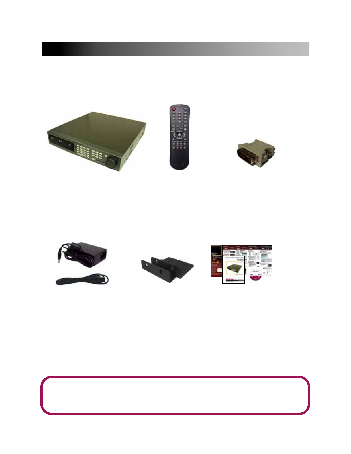
GETTING STARTED
DIGITAL VIDEO RECORDER
POWER CABLE
AND POWER ADAPTER
QUICK START GUIDE,
MANUAL, (ELECTRONIC MANUAL
CD)
REMOTE CONTROL
MOUNTING KIT
DVI TO VGA ADAPTER
The system comes with the following components:
HARD DRIVE SIZE, NUMBER OF CHANNELS, AND CAMERA CONFIGURATION MAY VARY
BY MODEL. PLEASE REFER TO YOUR PACKAGE FOR SPECIFIC CONTENT DETAILS.
CHECK YOUR PACKAGE TO CONFIRM THAT YOU HAVE RECEIVED THE COMPLETE SYSTEM,
INCLUDING ALL COMPONENTS SHOWN ABOVE.
1
Page 14
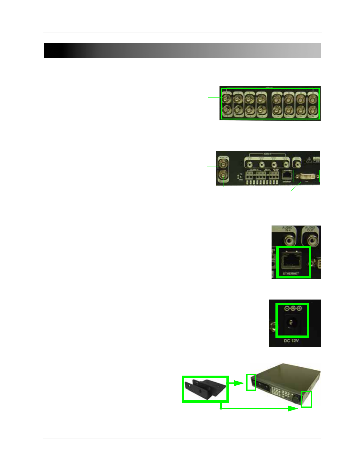
BASIC SETUP
Figure 1.0 Connect BNC cameras to the system (*16-channel
shown).
Figure 1.1 Connect to a DVI/VGA/CCT V monitor, or a TV. VGA
monitors require a DVI to VGA converter (not included).
Figure 1.2 Connect an RJ45 network cable into the
ETHERNET port.
Figure 1.3 Connect the power cable.
BNC IN
Figure 1.4 OPTIONAL—Attach mounting kit for rack mounting
MONITOR
OUT
SPOT OUT
DVI OUT
1. CONNECT THE CAMERAS
a. Connect BNC cameras to the BNC IN
ports on the rear panel.
2. CONNECT A MONITOR
a. Connect up to three monitors to the
system using the DVI port, Monitor, or
Spot Out port (see figure 1.1).
NOTE: VGA output requires a DVI to VGA
adapter (not included).
3. CONNECT THE ETHERNET
CABLE
a. Connect an Ethernet cable to the
Network port (LAN) on the rear panel of
system (see figure 1.2); connect the
other end of the Ethernet cable to an
empty LAN port on your router or switch
(not included) .
4. CONNECT THE POWER
CABLE
a. Connect the power cable to the DC 12V
port on the rear panel of the system;
connect the power adapter to an outlet,
power strip, or surge protector.
OPTIONAL: Mount the system to a rack
a. Use the included mounting kit to mount
the system to a rack.
2
Page 15

FRONT PANEL
1
2
3
5
Figure 2.0 Front panel (16-channel model shown; optical drive brand may not be as shown.)
6
4
7
8 9
10
1. Optical Drive: DVD-RW drive for data backup; drive can be replaced with an HDD if desired (not
included; hard drive bay required)
2. IR Sensor: Infrared (IR) sensor for the remote control.
3. Quick Menu Buttons:
• DISPLAY: Opens the display menu to choose between display configurations
• SEARCH: Open the Search menu
• SETUP: Open the Setup menu—select Main Menu (System Setup) or Record Menu (Record
Setup)
• PTZ/Focus: Open the PTZ menu*
NOTE: Press each button twice: the first press will open the Status Bar; the second press will open the
selected menu.
NOTE: By default, login is required when opening system menus. However, you can choose to disable this
password requirement. For details,
*PTZ cameras are not included with the system.
see “System Management” on page 38.
3
Page 16

Front Panel
Figure 2.01 Front panel (16-channel model shown)
1
2
3
5
6
4
7
8 9
10
Front Panel (cont’d.)
4. Playback Buttons:
• : Increase reverse playback speed -1X,- 2X, -4X, -8X, -16X,- 32X, -64X
• : Reverse playback
• : Pause/play
• : Forward playback
• : Increase forward playback speed 1X, 2X, 4X, 8X, 16X, 32X, 64X
• S: Menus: Move cursor up; PTZ: Tilt up
• T: Menus: Move cursor down; PTZ: Tilt down
• W: Menus: Move cursor left; PTZ: Pan left
• X: Menus: Move cursor right; PTZ: Pan right
• : Enter/confirm menu selections / Exit menu selections
5. HOLD button: Press to hold the position of the Jog/Shuttle Wheel during playback (i.e. turn the Shuttle
Wheel to increase/decrease playback speed, and then press the HOLD button to maintain the selected
speed).
6. Jog Ring/Shuttle Wheel: Use the Jog Ring/Shuttle Wheel during playback and PTZ control:
• Playback: Turn the Shuttle Wheel clockwise to increase playback speed 1X, 2X, 4X, 8X, 16X,
32X, 64X; turn the Shuttle Wheel counter-clockwise to decrease playback speed -1X, -2X, -4X,
-8X, -16X, -32X, -64X; turn the Jog Ring to advance frame-by-frame
• PTZ Control: Turn right to zoom IN, turn left to zoom OUT*
7. Channel/Number buttons: Press to view selected channels in full-screen; press to enter passwords in
login windows.
NOTE: Channel/number buttons may vary depending on model; 16-channel model shown.
8. POWER: Press to open the Power Off/Log Off menu; press to power the system on (login required).
9. USB ports: Connect USB devices such as mice, flash drives, and external HDDs.
NOTE: External USB devices are not included with the system.
10. LED Indicators: LED indicators for PWR (power), REC (record), NET (network), ALM (alarm)
4
Page 17
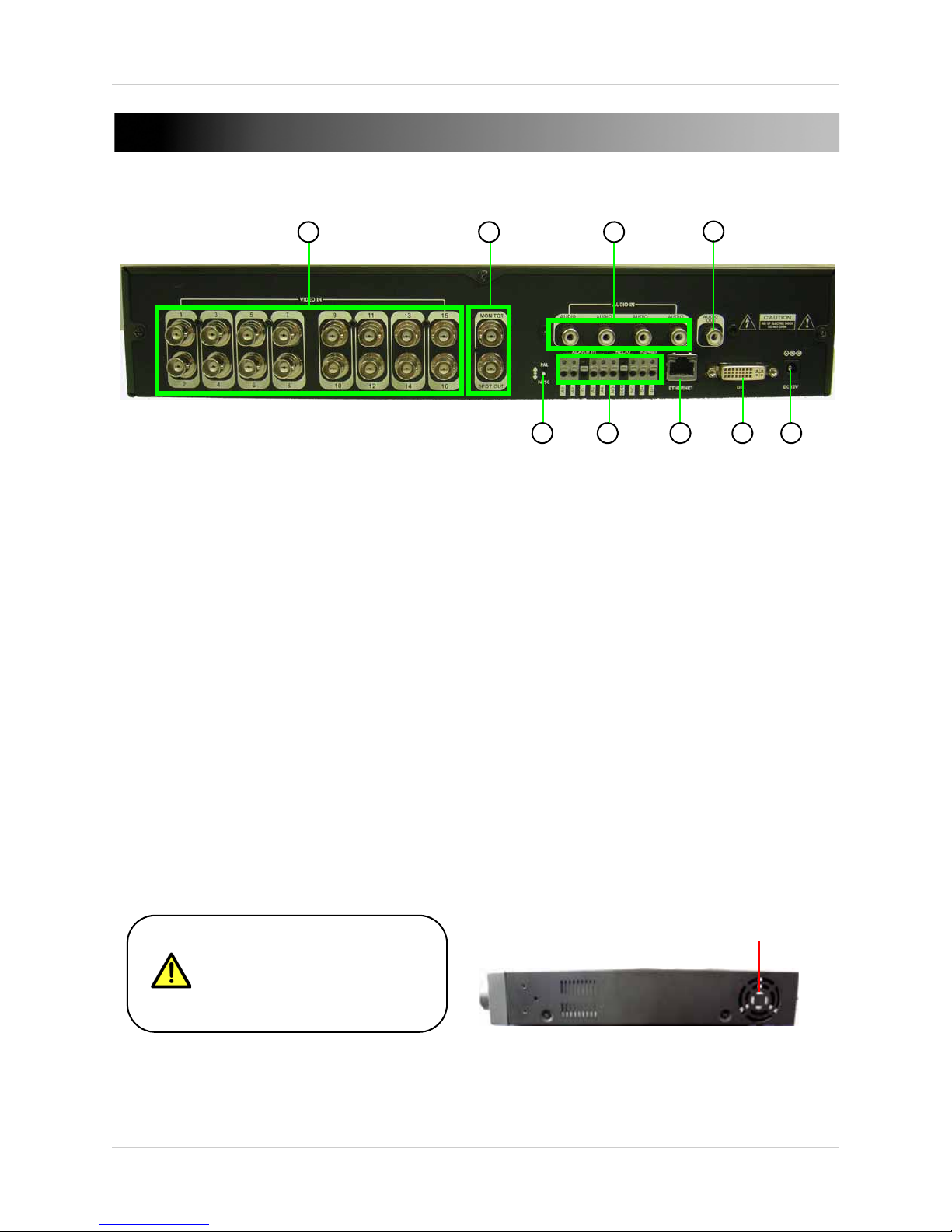
REAR PANEL
3
6
Figure 2.2 Rear panel (16-channel model shown)
1 2
4
5
7
8 9
Keep the exaust fan on the side
panel clear for proper ventilation.
Inadequate ventilation causes the
unit to overheat.
Exaust Fan
1. VIDEO IN : Camera input ports for BNC cameras; (16-channel configuration shown).
2. MONITOR: Composite output (top) to connect the system to a secondary monitor or DVR.
• SPOT OUT: Spot Monitor output (bottom) (Spot monitor only displays cameras, not system
menus).
3. AUDIO IN: Connect up to four audio inputs.
4. AUDIO OUT: Connect a single audio output.
5. PAL / NTSC : Switch between PAL and NTSC video output.
6. ALARM IN: Alarm block to connect external alarm or motion devices (not included).
• RELAY: One alarm output can be connected.
•
RS-485: PTZ (Pan, Tilt, Zoom) camera connection.
7. LAN: Connect an Ethernet cable to connect the system to a router or switch (not included).
8. DVI: DVIoutput to connect the system to a DVI monitor (not included). Use a DVI to VGA adapter (not
included) to connect a VGA monitor to the system.
9. DC 12V: Port for 12V power cable (included).
5
Page 18
CONTROL DEVICES
9
10
4
5
6
7
8
2
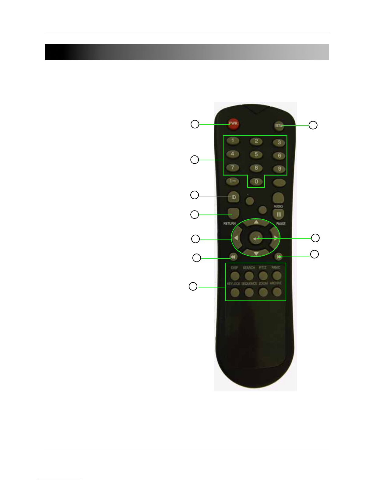
Figure 3.0 Remote Control
1
3
Remote Control
The remote control is the primary input device
for the system.
1. PWR: Press to power the system ON/OFF (password
required).
2. SETUP: Press to open the system menu.
3. Channel buttons: Press to view individual channels
in full-screen; press to input passwords; when
entering camera titles, press for alpha-numeric
characters.
4. ID: Press to select the DVR ID.
NOTE: If using several systems in a stack, you can use
one DVR ID to control all the systems with one remote
control, or apply unique DVR IDs to each system to
control them with individual remote controls.
5. RETURN: Press to cancel/deselect previous screen.
6. ENTER: Press to confirm menu options/selections.
7. Navigation/Menu: Press for playback control, menu
navigation, and PTZ/focus control.
• S: Press to move cursor up; increase values in
certain menu options
• T: Press to move cursor down; decrease values in
certain menu options
• W: Press to move cursor left
• X: Press to move cursor right
• : Press to pause playback
8. : Press to increase reverse playback speed 1X,
2X, 4X, 8X, and 16X.
9. : Press to increase forward playback speed 1X,
2X, 4X, 8X, and 16X
10. Mode buttons:
• DISP: Press to change the display view
• SEARCH: Press to open the Search Menu
• P/T/Z: Press to open the PTZ control menu
• PAN IC: Press to start/stop panic recording
• KEYLOCK: Press to lock buttons on the remote
control and front panel
• SEQUENCE: Press to start/stop Auto Sequence
mode
• ZOOM: Press to enable/disable Zoom mode
• ARCHIVE: Press to open the Archive menu
6
Page 19
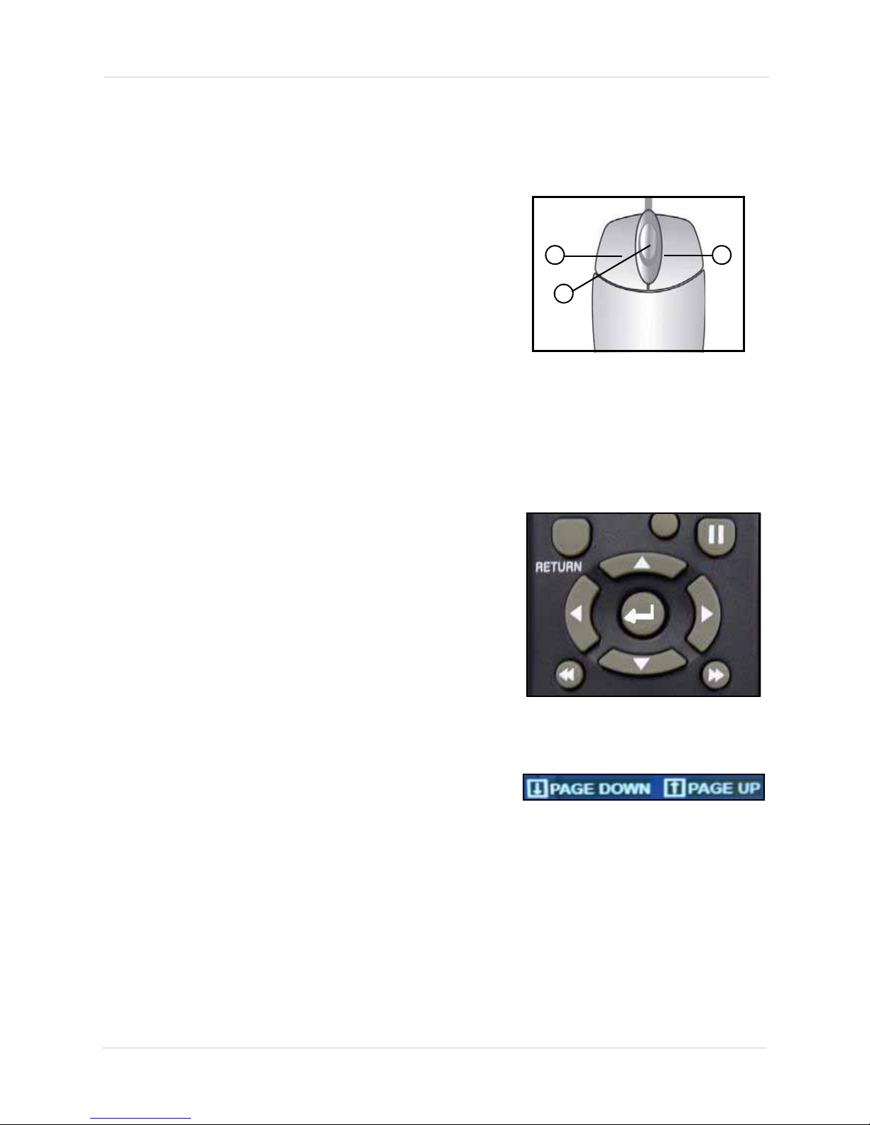
Mouse Control
1 2
3
Figure 3.1Mouse buttons
Figure 3.2 Remote control buttons
Figure 3.3 Page DOWN/Page UP (16-channel
models only)
The mouse is an optional control device for the system.
NOTE: A mouse is not included with this system.
To connect a USB mouse:
• Connect a USB mouse to the USB port on the front panel
NOTE: If using a PS/2 mouse (not included), a PS/2-to-USB
adapter (not included) is required
1. Left-Button: While in a split-screen display mode,
double-click an individual channel to view it in full-screen;
double-click again to return to the split-screen display mode.
While navigating menus, click to select a menu option.
2. Right-Button: Right-click anywhere on the screen to open the
Quick Menu.
3. Scroll-Wheel: N/A
Tips and Tricks
When navigating the menus using the remote control,
perform the following:
• Press the STWX buttons to move the on-screen
cursor
• Press the ENTER button to select an option (cursor turns
from GREEN to YELLOW)
• Press the RETURN button to de-select the option (cursor
turns GREEN)
Quickly Access System Information
• To access vital system information such as your MAC
address and IP address, press ENTER o n your re mote or
press the ENTER button on the front panel.
If your system has 16 channels, you may only see CH1~8 in
some menus.
• Select PAGE DOWN / PAGE UP to turn menu pages to
see all the channels on your system.
7
Page 20
Using the System
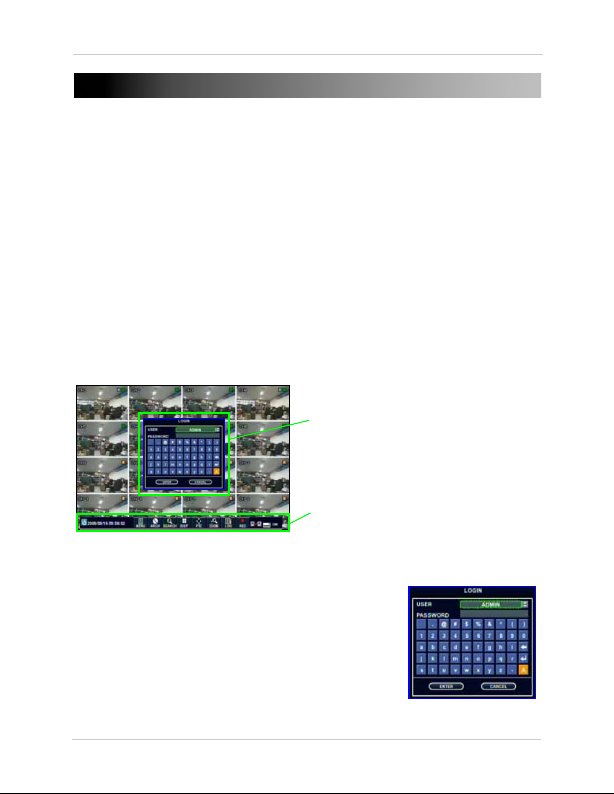
Figure 4.0 Log on to the system after start-up
Status Bar
Virtual
Keyboard
Figure 4.1 Virtual Keyboard
USING THE SYSTEM
With the system properly connected, you can power on and begin using the system.
Powering On The System
To power on the system:
1. Press the POWER button on the remote control or front panel. After an initial loading
sequence, the system displays a live split-screen mode. By default, the system begins
recording continuously from any connected cameras.
2. Using the Virtual Keyboard, enter your ADMIN password (by default, 1234) and select ENTER
to log onto the system.
NOTE: The default system administrator (ADMIN) password is 1234. For complete information
on changing your password and managing users on the system,
To power off the system:
1. Press the PWR button on the remote control to open the Status Bar; press the PWR button
again to open the Log Off/Power Off window.
2. Select POWER OFF and press ENTER on the remote control or front panel.
3. Using the Virtual Keyboard, enter your ADMIN password (by default, 1234) and select ENTER
to log off the system.
see “User” on page 41.
Using the Virtual Keyboard
Use the Virtual Keyboard to enter passwords and camera
titles on the system.
To use the Virtual Keyboard:
1. Select any desired letter, number, or character.
2. Press ENTER on the remote control or front panel.
NOTE: If desired, select "A" and press ENTER to shift
between upper and lowercase letters.
8
Page 21
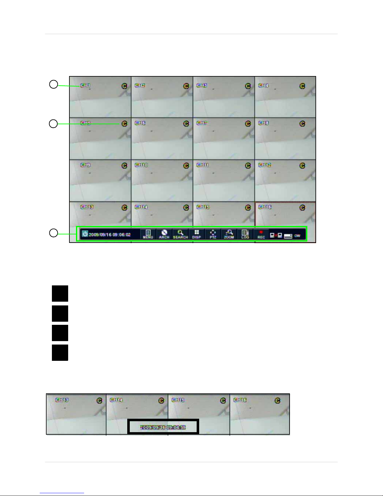
On-Screen Display
Figure 4.2 Main system display (16-channel model shown)
1
2
3
C
M
P
Continuous Recording
Motion Recording
Panic Recording
Alarm Recording
A
Figure 4.3 Date/Time stamp
By default, the system launches with a live, split-screen view:
Using the System
1. Channel Title: Display the channel number or title.
2. Recording Status: Different icons represent different recording modes: Continuous, Motion, Schedule,
and Panic.
NOTE: For details, see “Using the Recording Menu” on page 50.
3. Status Bar: Press the SETUP button to open the Status Bar at the bottom of the screen. When the
Status Bar is not in use, only the date and time remain on-screen.
9
Page 22

Using the System
Figure 5.0 Status Bar. The Status Bar auto-hides after 10-seconds of inactivity.
10
1 2 3 4 5 6 7 8 9
1211 13
NOTE: You must enter your user name and
password when logging off or powering off
the system.
Figure 5.1 Power/log off options
Using the Status Bar
The Status Bar gives you access to the many modes and functions of the system.
To open the Status Bar:
• Press the SETUP button on the remote control or front panel
OR
• Move the mouse (not included)
NOTE: By default, login is required when opening menus on the system. If desired, you can
disable the password requirement from the System Management menu. For details,
“System Management” on page 38.
1. Power: Log off the current user or power off the system.
see
2. Date & Time: Shows the current date and time on the system.
3. MENU: Opens the system menu (System Setup, Record Setup). For details, see “Using the
System Menu” on page 29.
4. ARCH.: Opens the Archive (Backup) menu. For details, see “Archiving” on page 24.
5. SEARCH: Opens the Search menu. For details, see “Search” on page 20.
6. DISPLAY: Opens the pop-up display window, which allows you to select up to six display
modes as well as enable/disable Auto Sequence. For details,
see “Changing Display Modes”
on page 11.
7. PTZ: Opens the PTZ control window. For details, see “PTZ” on page 15.
8. ZOOM: Starts/stops zoom mode for selected channel. For details, see “Zoom” on page 14.
9. LOG: Opens the Log File menu. For details, see “Log” on page 16.
10. REC: Starts/stops Panic Recording Mode. For details, see “Panic Recording” on page 19.
11. Network Status: Shows the status of the network connection. Green=network connection is
stable; Blue=network connection is experiencing difficulty; Red=network connection is
unstable.
12. HDD Status: "OW" indicates disk overwrite is enabled. For details, see “Disk Manage” on
page 49.
10
Page 23

Changing Display Modes
Full-Screen
Quad
6-channel
8-channel
9-channel
(Bottom-right square blacked
out on 8-channel models)
16-channel
(16-channel
models only)
Auto Sequence
Figure 5.2 Power/log off options
Tip!
From quad and
split-screen view,
double-click any
channel to view it
in full-screen.
Double-click
again to return to
the previous view.
The system has six different display modes as well as an Auto Sequence mode.
Using the System
To change display modes:
1. Press the DISP button twice. The display pop-up window opens.
2. Select one of the following and press the ENTER button:
• : Single channel full-screen mode
• : Quad
• : 6-channel split-screen
• : 8-channel split-screen
• : 9-channel split-screen
• : 16-channel split-screen
NOTE: Select the Quad and Split-Screen buttons repeatedly to change
the layout of displayed channels.
USING AUTO SEQUENCE
Auto Sequence allows you to view all channels in full-screen in an
automatic sequence.
To start Auto Sequence:
1. Press the SEQUENCE button. Auto Sequence begins.
2. Press the SEQUENCE button to exit Auto Sequence mode.
You can program more complex sequence in the system’s Setup Menu. For details, see
“Sequence” on page 34.
11
Page 24

Using the System
Figure 6.0 Quick Menu
Figure 6.1 Quick Play main screen
Figure 6.2 Open the Quick Menu and select a
playback time
Quick Menu (Mouse Only)
If using a mouse (not included), right-click any channel to open the Quick Menu. The Quick Menu
allows for quick access to key functions, including Panic Recording, Playback and PTZ.
To use the Quick Menu:
1. Right-click on a desired channel. The Quick Menu
opens.
2. Select one of the following:
• PTZ: Open the PTZ control window (login required)
• Zoom: Open Zoom Mode. For details, see “Zoom” on
page 14.
• Playback: Opens Quick Play to view video from 10
seconds ago, 20 seconds ago, 30 seconds ago, or 1
minute ago in a pop-up window. You can also select Go
to.. to open the Time Selection window.
• Record Start (Stop): Start/stop panic recording.
NOTE: Panic Recording applies to ALL connected
cameras.
3. Click anywhere outside the Quick Menu to exit.
QUICK PLAY (MOUSE ONLY)
To begin playback:
1. Right-click on any desired channel. The Quick Menu
opens.
2. From the Quick Menu, select Playback.
3. Select one of the following:
• 10 sec ago
• 20 sec ago
• 30 sec ago
• 1 min ago
NOTE: Selecting "10 sec ago ~ 1 min ago" will open the
Quick Play main screen—continue to step 4.
• go to...
NOTE: Selecting "go to..." will open the Time Selection
window—go to step 5.
4. The video immediately begins playing. Use the following
buttons to control playback:
• : Increase reverse playback speed 1X, 2X, 4X, 8X, 16X,
32X, or 64X
• : Jump to beginning of clip
•
: Reverse playback
: Pause/Play
•
•
: Forward playback
12
Page 25
Using the System
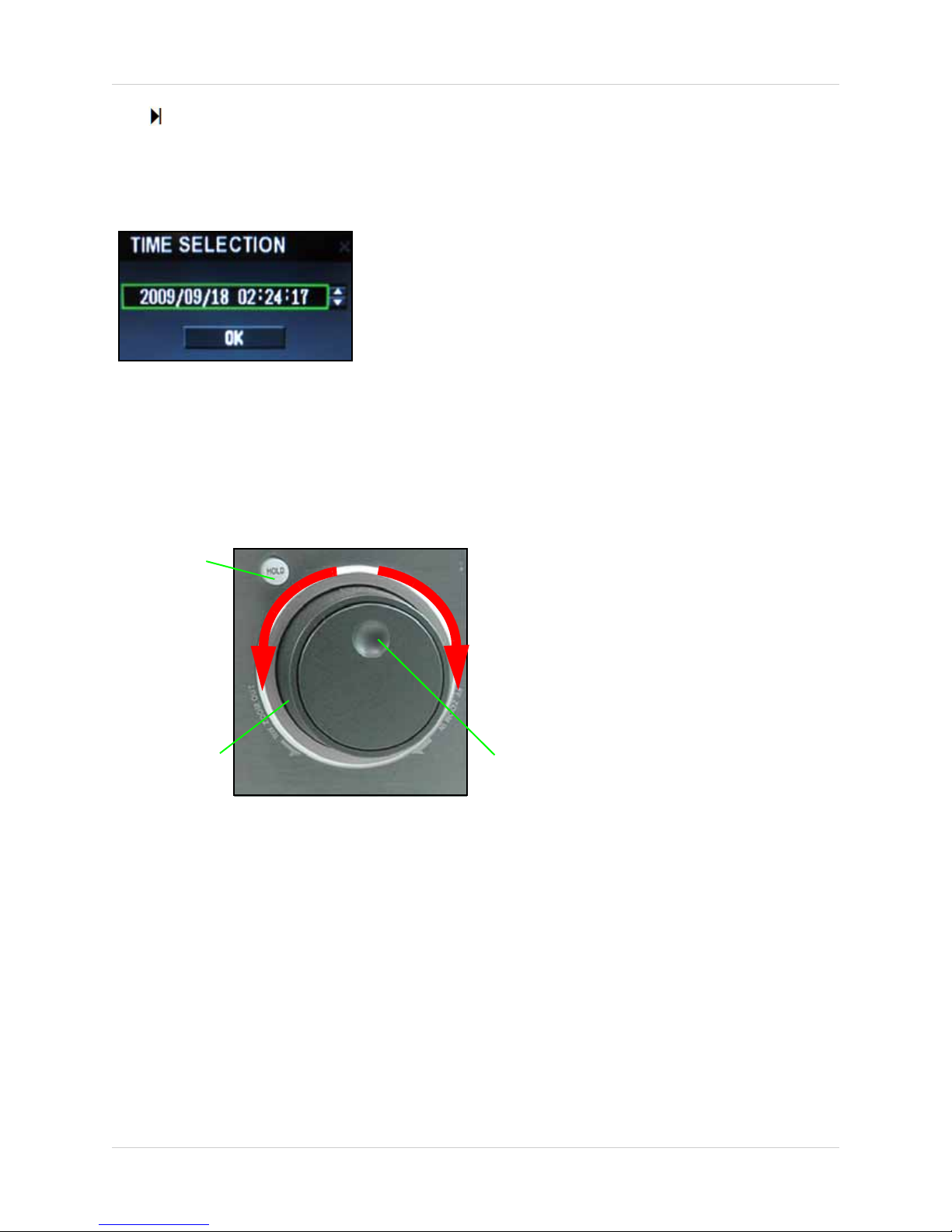
Figure 6.3 Time Selection window
Jog Ring
Shuttle Wheel
Hold Button
Zoom OUT
(Turn Shuttle Wheel
counter-clockwise)
Zoom
IN
(Turn Shuttle Wheel
clockwise)
Figure 7.0 Jog Ring/Shuttle Wheel
• : Jump to end of clip
: Increase forward playback speed 1X, 2X, 4X, 8X, 16X, 32X, or 64X
•
• X: Close mini-player
5. If you select "Go to..." the Time Selection window opens. Select the year, month, day, hour,
minutes, and seconds and adjust by clicking the UP /DOWN arrows.
6. When you have selected a date and time, click OK. The Quick Play main screen opens. Use the
playback controls as described in step 4.
Using the Jog Ring/Shuttle Wheel
During Playback, you can use the Jog Ring/Shuttle Wheel on the front panel to increase/decrease
playback speed.
To use the Jog Ring/Shuttle Wheel:
1. Perform any of the following:
• Turn the Shuttle Wheel steadily clockwise to increase playb ack s peed ( 1X, 2X , 4X, 8 X, 16X , 32X,
64X). Release the Shuttle Wheel to pause playback.
• Turn the Shuttle Wheel steadily counter-clockwise to increase reverse playback speed (-1X,
-2X, -4X, -8X, -16X, -32X, -64X). Release the Shuttle Wheel to pause playback.
• Press the HOLD button to maintain the selected speed (even if the Shuttle Wheel is released).
• With playback paused, turn the Jog Ring clockwise or counter-clockwise to advance the video
frame-by-frame.
NOTE: Playback speed and direction can also be controlled using the five playback buttons
located beside the Jog Ring/Shuttle Wheel on the front panel.
2. Press RETURN on the remote control or front panel to exit playback.
13
Page 26
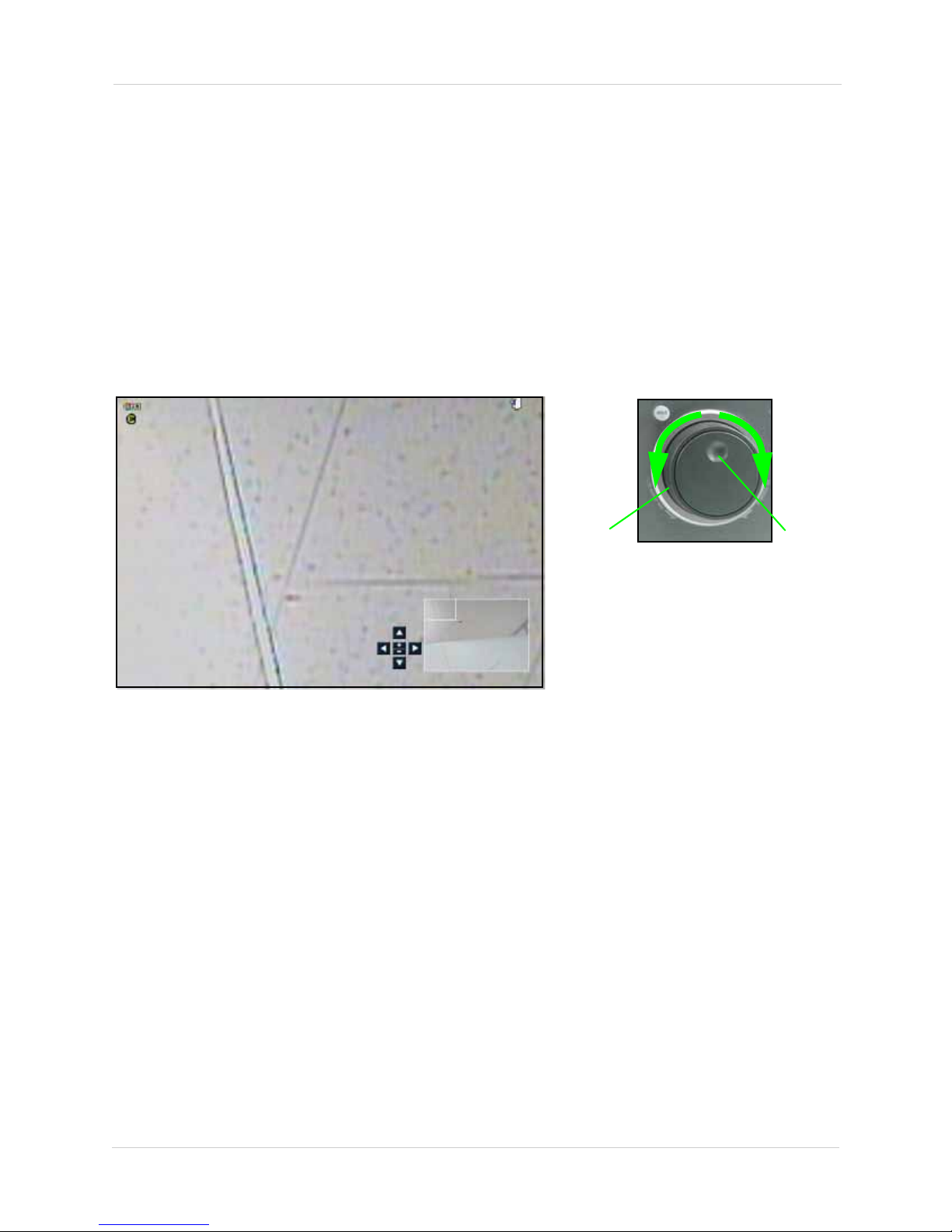
Using the System
Figure 8.0 Zoom frame (full-screen only)
Zoom OUT
Zoom IN
Shuttle
Wheel
Jog Ring
Zoom
Use the system’s built-in 8X digital zoom to get a closer look at images in full-screen (full-screen
mode only).
To use zoom:
1. From live viewing, select a channel to view in full-screen (press one of the number buttons on
the remote control or front panel).
NOTE: The zoom function will not work if the main display screen is in quad or split-screen
configurations.
2. Press the ZOOM button. By default, the system will zoom in to the center of the selected
channel.
3. Perform any of the following:
• Press the STWX buttons to scan the image
• Turn the Shuttle Wheel steadily clockwise to zoom IN
• Turn the Shuttle Wheel steadily counter-clockwise to zoom OUT
4. Click the RETURN button to exit Zoom mode and return to live viewing.
14
Page 27
Using the System
Figure 9.0 Zoom frame (full-screen only)
1
5
2
3
4
6
87
Figure 9.1 Zoom frame (full-screen only)
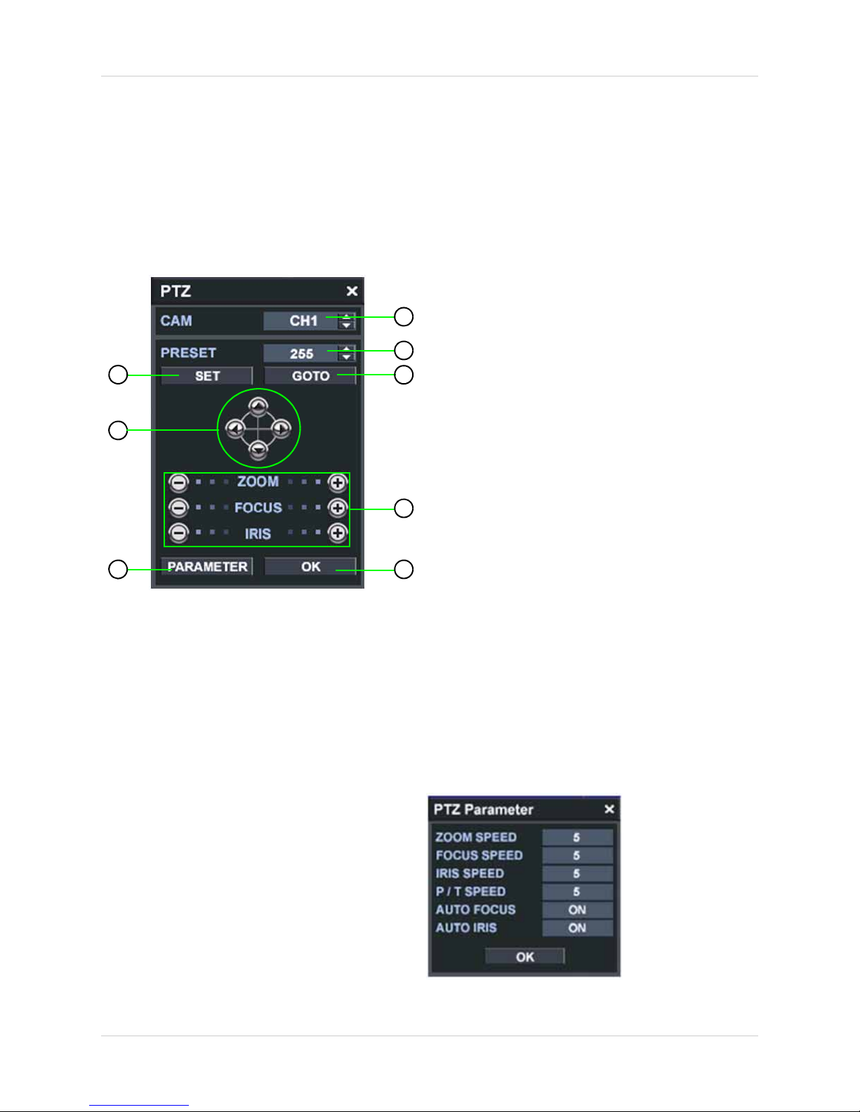
• The PTZ Parameter
menu displays the
current settings of your
PTZ camera (Zoom
speed, Focus speed,
Iris speed, Pan/Tilt
speed, Auto Focus on/
off, Auto Iris on/off)
• Click
OK to exit
PTZ
Use the PTZ menu to control any PTZ cameras (not included) connected to your system. For
details on connecting PTZ cameras,
NOTE: It is recommended to use a mouse (not included) with the PTZ control menu.
To open the PTZ menu:
• Press the PTZ button on the remote control. If necessary, login using your user name and
password (by default, user name: ADMIN, password: 1234).
see “Appendix D: Connecting PTZ Cameras” on page 101.
1. CAM: Select channels
2. PRESET: Select presets.
3. SET: Save a preset.
4. GO TO: Go to a saved preset position.
5. Pan/Tilt Navigation:
• ST: Tilt camera up/down
•
WX: Pan camera left/right
6. ZOOM/FOCUS/IRIS: Increase or
decrease Zoom, Focus and Iris focusing.
7. PARAMETER: Opens the Parameter
menu (see figure 9.1).
8. OK: Close the PTZ menu.
For details on connecting a PTZ camera to
your system,
PTZ Cameras” on page 101.
see “Appendix D: Connecting
15
Page 28
Using the System
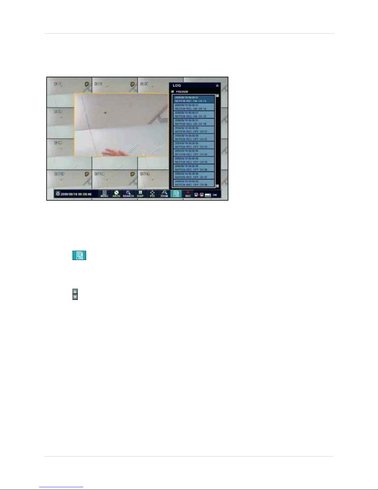
Figure 10.0 Log menu with Preview window
Log
Use the Log file to view recent events on the system, as well as view a preview video of each of
these events.
NOTE: Log works with mouse only (not included).
To open the log file:
1. Move the mouse to open the Status Bar.
2. Click (Log). The Log menu opens.
NOTE: By default, the Log menu opens with the Preview option enabled.
3. Click any file in the log list to view video of the event in the Preview pane.
4. Click to move up and down the list.
5. Select/deselect the PREVIEW box to show/hide the Preview pane.
6. Click X to exit.
16
Page 29
Setting the Time
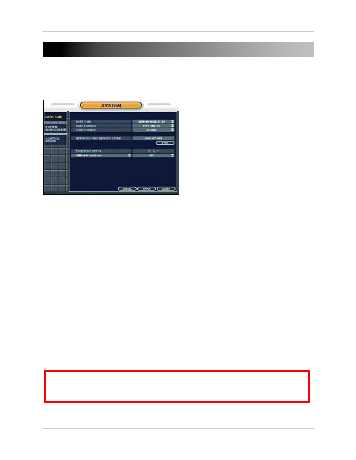
Figure 11.0 Time menu
ATTENTION: If the saved time is earlier than the current time on the system, you will be
warned that overlapped data will be erased. Select YES and press ENTER to accept the
changes. Please allow a few moments for the overlapped video data to be deleted.
SETTING THE TIME
It is highly recommended to set the time on the system before doing any recording. The time can
be synchronized to a Network Time Server, or can be set manually.
To set the date and time:
1. Press the SETUP button to open the Status Bar.
2. Select MENU and press ENTER.
3. Select SYSTEM SETUP and press ENTER. If necessary, login using your ADMIN password (by
default, 1234). The Main Menu opens.
NOTE: For more details, see “Date/Time” on page 38.
4. From the Main Menu, select SYSTEM and press ENTER. The System menu opens.
5. Select DATE / TIME and press ENTER.
6. Perform one of the following:
• Under NETWORK TIME SERVER SETUP, select SYNC. and press ENTER to synchronize the
system to the network time server (the system must be properly connected to your network
in order to use this function)
OR
• Under DATE TIME, manually select the date and time (yyyy/mm/dd; hh/mm/ss) and adjust
using the
NOTE: If desired, change the Date Format and the Time Format.
7. Select APPLY and press ENTER to save your changes.
8. Select CLOSE and press ENTER to exit.
ST buttons
17
Page 30
Recording
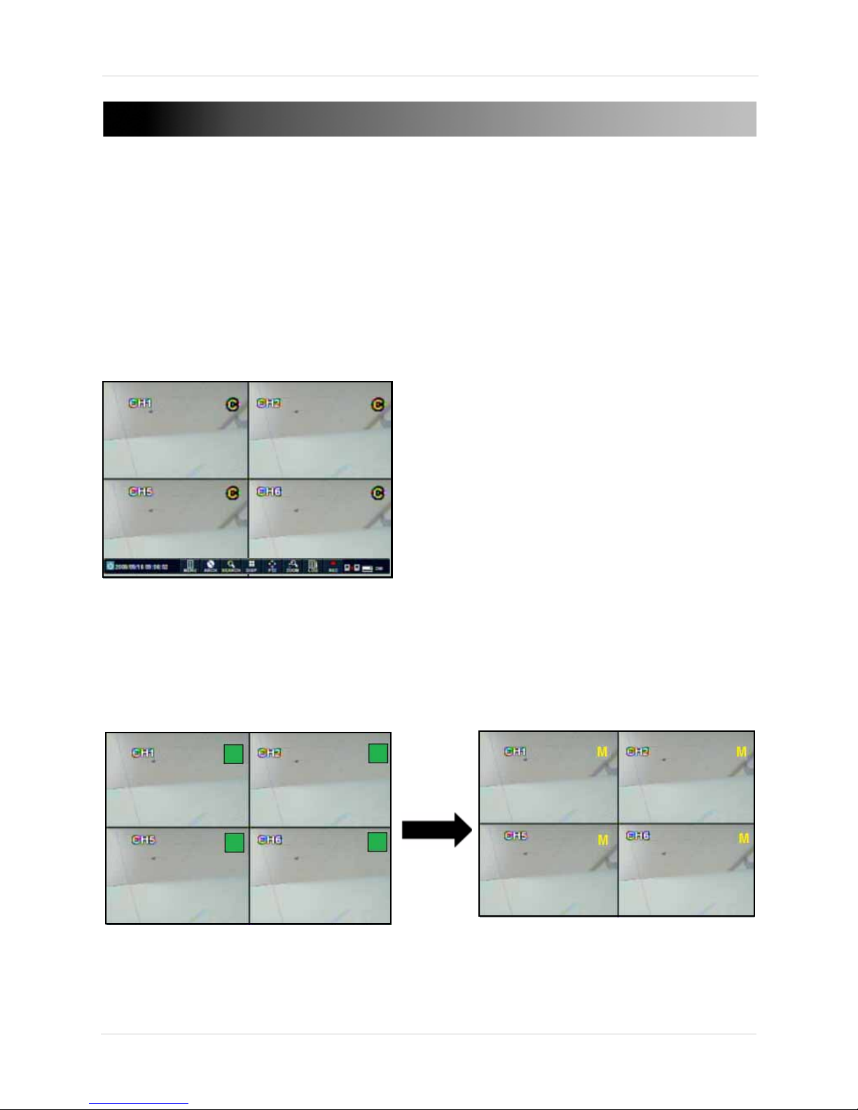
Figure 12.0 Continuous recording on all channels (Quad display mode shown)
Figure 12.1 Motion Recording icons (inactive and active)
Motion Recording enabled but inactive—
system
IS NOT recording.
Motion Recording activated—system is recording.
RECORDING
By default, the system is set to record continuously at startup from any connected cameras. It is
highly recommended to keep continuous recording on at all times.
The system can perform Continuous Recording, Motion Recording, Continuous + Motion
Recording, Alarm Recording, and Panic Recording. You can set a customized daily or weekly
recording schedule using these recording modes. For complete details,
Menu” on page 50.
Continuous Recording
By default, all camera channels are enabled with continuous recording. During Continuous
Recording, a yellow "C" appears in the top-right corner of each channel.
see “Using the Recording
Motion Recording
The system will only record when motion is detected by a camera. When Motion Recording is
enabled but not active, a green square appears in the top-right corner of every channel—the
green square indicates the system IS NOT recording. When motion is detected, a yellow "M"
appears in the top-right corner of each channel. You can set the pre and post recording time in
the Recording Operations menu.
18
Page 31

Recording
Figure 12.2 Panic Recording icon (top-right corner)
Continuous + Motion Recording
The system records continuously from any connected cameras; when motion is detected, the
system will record according to customizable motion recording parameters.
Alarm Recording
When an alarm input is triggered, the system will continue to record, but can apply unique
recording parameters that you can set in the Alarm menu (Main Menu>Alarm). You can also set
the system to activate an alarm output. For example, a window sensor (not included) connected
to the alarm input block on the rear panel is triggered; the system begins alarm recording and
simultaneously activates an external siren (not included) connected to the alarm output block on
the rear panel.
Panic Recording
Press the PANIC button on the remote control or click to start/stop Panic Recording. Panic
Recording features the highest quality recording parameters available on the system. A "P"
appears in the top-right corner during Panic Recording.
NOTE: Panic Recording will override any functions or operations currently on the system.
Recording Audio
The system can record up to four channels of audio. You must have an audio enabled camera or
self-powered microphone connected to the system in order to use this function. You can enable/
disable audio recording in the Continuous/Motion Recording menu. For details, see
page 51.
19
Page 32

Search
Figure 13.0 Search menu—Search by Time
Timeline Display
Calendar
Time
Note: The Panorama Playback feature will be enabled
in a future update.
SEARCH
View recorded video on the system using the Search menu. You can search by Time or by Event.
To open the Search Menu:
• Press the SEARCH button twice. If necessary, login using your user name and password.
Time Search
To search by Time:
1. Select SEARCH BY TIME and press ENTER.
2. Select the calendar and press ENTER. The calendar is highlighted in YELLOW.
3. Press the STWX buttons to select the date, the month and year. As different days are
selected, the timeline display changes to show recorded video from that day. Recorded video
is color coded:
• WHITE=Panic recording
• GREEN=Motion recording
• SKY BLUE=Continuous recording
• RED=Alarm recording
• PINK=Inactive motion recording ("NO RECORD" will appear during playback)
4. Press RETURN to deselect the calendar.
5. Select the Timeline Display and press ENTER.
6. Press the STWX buttons to move the Timeline Cursor. The time of the recorded content
appears below the calendar.
7. Press RETURN to deselect the Timeline Display.
8. Select PLAY and press ENTER. Playback begins. For details, see “Playback” on page 22.
20
Page 33

Event Search
Figure 13.3 Search menu—Search by Event
To search by Event:
1. Select SEARCH BY EVENT and press ENTER.
Search
2. Press the STWX buttons and the ENTER button to select/deselect individual channels or
select ALL.
3. Press the STWX buttons and the ENTER button to select/deselect SETUP, MOTION,
SMART (HDD events), SYSTEM, ALARM, V. LOS S, RECORD, or select ALL.
4. Under FROM, enter a start time. Under TO, enter a stop time.
NOTE: Selected items highlight with a GREEN box. Press ENTER on highlighted items to turn
the highlight box YELLOW. Once the box turns yellow, you can adjust the settings.
5. Select NEAREST (default) or FARTHEST to help organize the search results.
6. Select SEARCH and press ENTER. The Date/Time and Log fields become populated with the
event data.
NOTE: For 16-channel systems, select PAGE UP/PAGE DOWN to change pages to view other
channels.
7. Select an event from the Log list and press ENTER. Playback for the selected event begins.
For details,
see “Playback” on page 22.
21
Page 34

Playback
Figure 14.0 Playback (16-channel model shown)
DISPLAY
REWIND
REVERSE
PLAY
PAU SE/
PLAY
FORWARD
PLAY
FAS T
FORWARD
ARCHIVE
RETURN
(exit)
PLAYBACK
Playback Mode is accessed through the Search Menu. You can also open Quick Play mode from
the Quick Menu (mouse only).
NOTE: By default, playback begins in split-screen mode (number of split-screen channels varies
by model).
To open Playback mode:
1. Open the SEARCH menu. If necessary, login using your user name and password.
2. Search for recorded video using the calendar and time bars.
3. Select PLAY and press ENTER. Playback begins.
4. During playback, perform any of the following:
• DISP button: Change the display view: single channel, quad, or split-screen
•
: Increase reverse playback speed -1X, -2X, -4X, -8X, -16X, -32X, -64X
•
: Reverse playback
•
: Pause/play
•
: Forward playback
•
: Increase forward playback speed 1X, 2X, 4X, 8X, 16X, 32X, 64X
NOTE: You can use the front panel buttons to control video playback.
• Press the ARCHIVE button to backup the selected video to an Archive List
NOTE: If using a mouse:
5. Press RETURN to exit playback
22
Page 35

Archiving Video
Figure 14.1 Archiving Setup menu—enter a tag and select START
Figure 14.2 Select CONTINUE or select STOP
Figure 14.3 Select RESERVE
Figure 14.4 Select OK in the success prompt
You can backup video to an AVI archive list while in Playback Mode.
To setup a video archive:
1. During playback, press the ARCHIVE
button on the remote control or click
The Archive Setup window opens.
2. Select TAG and press ENTER to open the
Virtual Keyboard and enter a name/title
for the video.
3. Under AVI CHANNEL, select/deselect the
channel(s) from which to archive the
video.
NOTE: FROM (start time) begins when you
select START; TO (stop time) will be set
once you manually STOP the archive
process (see step 6).
4. Select START and press ENTER. The
Archive Setup window closes and the
system returns to playback.
5. Press the ARCHIVE button or click to
open Archive Setup window.
6. Select CONTINUE and press ENTER to
allow the archive setup to continue to a
desired time (Archive Setup window
closes)
OR
6. Select STOP and press ENTER to stop the
archive setup.
7. Select RESERVE and press ENTER.
Select OK and press ENTER to close the
success prompt.
8. Select CLOSE and press ENTER to exit.
.
The archived video has been added to the AVI
Archive List. For more details,
Data Management” on page 27.
23
see “Reserved
Page 36

Archiving
Figure 15.0 New Archiving menu (16-channel model shown)
Tip!
If using a mouse,
use the cursor to
help you quickly
select start and
stop times.
ARCHIVING
Use the Archiving menu to backup data to a USB flash drive, external USB HDD, or a blank DVD/
CD (not included).
NOTE: Only the ADMIN has authority to archive recorded data.
Before You Start
• Connect a USB flash drive/external USB HDD to the system or insert a blank DVD/CD in the
optical drive prior to archiving data
New Archiving
Use the New Archiving Menu to search for data on the system and copy to a USB drive or DVD/CD.
To open the New Archiving menu:
1. Press the SETUP button on the remote control to open the Status Bar.
2. Select ARCH and press ENTER. If necessary, login using your ADMIN password.
NOTE: Only the ADMIN has access to the Archiving menu.
NOTE: Video data is saved in AVI format. Video is compressed with H.264.
24
Page 37

ARCHIVING DATA
Figure 15.1 Set a tag and start/stop times
Figure 15.2 Set criteria and select QUERY
Figure 15.3 Log and Memo options
Search for data using start and stop times and
then archive the data to a USB device or DVD/
CD.
To search for data:
1. Select NEW ARCHIVING and press ENTER.
2. Under TAG, press ENTER to open the
Virtual Keyboard and enter a name/title for
your archive file.
NOTE: A tag is required for reserving and
burning archive data.
NOTE: You can also tag recorded data using
the Playback menu. For details,
“Archiving Video” on page 23.
3. Under DEVICE, select the device for
archiving: USB flash drive, USB HDD, or
the CD/DVD drive.
NOTE: The device name may appear and not
the device itself. For example, in figure 15.1,
"Data Traveller 2.0" is the type of USB flash
drive connected to the system.
4. Select FROM and set a start time for the
search.
5. Select TO and set a stop time for the
search.
see
7. Select QUERY and press ENTER. The
system scans for recorded data based on
your selected criteria. The size of the
archive data appears under "ARCHIVING
INFO."
NOTE: If you receive an error message after
selecting Query, please ensure you have
entered correct start and stop times.
8. If desired, select RELEASE and press
ENTER to clear the search criteria.
Once you have queried the data, you can
Reserve the data (save the queried video to an
AVI archive list for burning or future reference)
or Burn the data (copy the data to a USB device
or blank CD/DVD).
6. Select ALL to select/deselect all channels,
or, press the
ST buttons to select/
deselect individual channels.
25
For details on Reserving and Burning data, see
page 26.
Archiving Options
If desired, you can apply the following archiving
options to your archive data:
• LOG: Select LOG to add a log text file to the
archived data
• MEMO: Select MEMO and press ENTER to
open the Virtual Keyboard; enter a short
description or comment for the archived
data (max. 20 characters)
Page 38

Archiving
Figure 15.4 Log and Memo options
Figure 15.5 Successful reserve prompt
BURNING DATA
Copy/write video data to a USB device or blank
CD/DVD.
NOTE: If you have not already done so, please
connect a USB device to the system, or
insert a blank CD/DVD in the optical drive.
To burn (copy) data to a USB drive or disc:
1. Open the NEW ARCHIVING menu and
search for recorded data using customized
criteria.
NOTE: Make sure you apply a tag to your
query.
2. Select QUERY and press ENTER. The
system scans for recorded data based on
your selected criteria. The size of the
archive data appears under "ARCHIVE
INFO."
3. Select BURN and press ENTER. The
Burning menu opens.
6. Select START and press ENTER. The
system will begin to extract data and then
write data to the drive or disc. This may
take several moments depending on the
size of the recorded data.
NOTE: Once copying is finished, the Burning
window will close.
7. Select CLOSE and press ENTER to exit.
NOTE: The recorded data is written to the
drive/disc in AVI format. The system also
copies a Backup player to view the video files
on your PC, as well as an AVI codec that
allows you to view the video files in Windows
Media Player
TM
.
RESERVING DATA
Reserving data allows you to save queried
video data to an AVI archive list for burning or
future reference. For more details,
“Reserved Data Management” on page 27.
To reserve data:
1. Open the NEW ARCHIVING menu and
search for recorded data using customized
criteria.
NOTE: Make sure you apply a tag to your
query.
see
4. Under DEVICE select your backup media
(CD, DVD, USB flash drive, or USB HDD).
5. Under BURNING TYPE, select BURN or
ERASE&BURN.
NOTE: If you select BURN, the archive data
will be burned/written to the drive/disc; if
you select ERASE&BURN, the system will
first erase any existing data on the USB
device or CD/DVD-RW, and then burn the
archive data.
2. Select QUERY and press ENTER. The
system scans for recorded data based on
your selected criteria. The size of the
archive data appears under "ARCHIVE
INFO."
3. Select RESERVE and press ENTER. A
success prompt is displayed on-screen.
4. From the prompt, select OK and press
ENTER.
26
Page 39

Archiving
Figure 15.6 Reserved Data Mangement menu
Figure 15.7 File information (AVI and snapshot)
Figure 15.8 Log and Memo options
NOTE: If you do not recei ve a success p rompt,
please make sure you have applied a tag to
the archive file
Reserved Data
Management
Use the Reserved Data Management menu to
manage your archived AVI.
VIEWING FILE INFORMATION
View information on reserved video and image
files.
To view file information:
1. Select RESERVED DATA MANAGEMENT
and press ENTER.
2. Select a file under AVI ARCHIVING LIST or
SNAPSHOT ARCHIVING LIST and press
ENTER. The file is highlighted in a light
grey frame.
3. Select INFORMATION and press ENTER.
The file information window contains the
following:
• TAG : The name of the file
• FROM: Start time
• TO: Stop time
• MEMO: Description or comment
• INFO: Size of the file
• AVI CHANNEL: Selected boxes indicate the
channel(s) present in the file
• LOG: Selected box indicates that a log was
applied to the archive data
4. Select CLOSE and press ENTER to exit.
BURNING FILES
Select files from the archive lists to copy to a
USB device or blank CD/DVD. Files can be
copied multiple times.
To burn (copy) a file:
1. Connect a USB device to the system or
insert a blank CD/DVD in the optical drive.
2. Select RESERVED DATA MANAGEMENT
and press ENTER.
3. Select a file under AVI ARCHIVING LIST
and press ENTER. The file is highlighted in
a light grey frame.
4. Select BURN and press ENTER. The
Burning menu opens.
5. Under DEVICE select your backup media
(CD, DVD, USB flash drive, or USB HDD).
6. Under BURNING TYPE, select BURN or
ERASE&BURN.
27
Page 40

Archiving
ATTENTION: The system immediately
deletes the files. Please use caution when
deleting files from the Archive Lists.
Figure 15.9 Files are immediately deleted when you click
DELETE
NOTE: If you select BURN, the archive data
will be burned/written to the drive/disc; if
you select ERASE&BURN, the system will
first erase any existing data on the USB
device or CD/DVD-RW, and then burn the
archive data.
7. Select START and press ENTER. The
system will begin to extract data and then
write data to the drive or disc. This may
take several moments depending on the
size of the recorded data.
NOTE: Once copying is finished, the Burning
window will close.
8. Select CLOSE and press ENTER to exit.
DELETING FILES
Delete video and image files in the archive
lists.
To delete a file:
1. Select RESERVED DATA MANAGEMENT
and press ENTER.
2. Select a file under AVI ARCHIVING LIST
and press ENTER. The file is highlighted in
a light grey frame.
3. Select DELETE and press ENTER.
4. Select CLOSE and press ENTER to exit.
28
Page 41

Using the System Menu
Figure 16.0 Select SYSTEM SETUP
Figure 16.1 System Setup (Main system menu)
USING THE SYSTEM MENU
To open System Setup:
1. Press the SETUP button. The Status Bar opens
2. Select MENU and press ENTER. The Setup window opens.
3. From the Setup window, select SYSTEM SETUP and press ENTER. If necessary, login using
your user name and password (by default, user name: ADMIN; password: 1234).
1. CAMERA: Configure camera setup, color setup, PTZ setup, and motion sensor settings.
2. DISPLAY: Configure OSD, Monitor, Auto Sequence, and Spot Out settings.
3. SOUND: Configure system audio, network audio, and buzzer settings.
4. SYSTEM: Set the date/time and configure system management options, and control devices.
5. USER: Set user management and user authorities and log out options.
6. NETWORK: Configure IP, DDNS, and email settings.
7. EVENT / SENSOR: Customize HDD events, alarm input/output, buzzer out, and email
notification.
8. DISK MANAGE: Set the Record Time Limit and overwrite, and format.
29
Page 42

CAMERA
Figure 17.0 Camera Setup menu
Use the Camera menu to configure
camera, color, PTZ and motion
settings.
CAMERA SETUP
Use the Camera Setup menu to change
camera titles, enable/disable covert camera,
and configure audio
To configure Camera Setup options:
• Select CAMERA SETUP and press ENTER
3. Select APPLY and press ENTER to save
your settings or select CANCEL to restore
defaults.
4. Select CLOSE and press ENTER to exit.
Audio
The system can record from up to four audio
channels. By default, channels 1~4 are
enabled for audio recording. Use the Camera
Setup menu to customize audio recording.
To enable/disable audio recording:
1. Under AUDIO, select a channel, and press
ENTER.
2. Select CH 1, CH 2, CH 3, CH 4, or OFF and
press ENTER.
3. Select APPLY and press ENTER to save
your settings or select CANCEL to restore
defaults.
4. Select CLOSE and press ENTER to exit.
NOTE: If your system has 16 channels, select
PAGE UP/PAGE DOWN to change pages.
Title
To change a camera title:
1. Under TITLE, select a channel and press
ENTER to open the Virtual Keyboard.
2. Enter a title for the camera (up to eight
alphanumeric characters), select OK and
press ENTER. The Virtual Keyboard closes.
3. Select APPLY and press ENTER to save
your settings or select CANCEL to restore
defaults.
4. Select CLOSE and press ENTER to exit.
Covert
To enable/disable covert camera:
1. Under COVERT, select a channel and press
ENTER.
2. Select ON/OFF and press ENTER. If ON,
the channel will appear blacked out
on-screen, but the system will actually be
recording.
NOTE: CH 1~4 refer to
If straying from the default configuration,
please ensure that you assign the correct
audio channel to the corresponding camera
channel. For example, you want to connect
audio-capable cameras to channels 1, 2, 7
and 8: under AUDIO, you would select CH1
for camera 1, CH 2 for camera 2, CH 3 for
camera 7, and CH 4 for camera 8.
audio
channels 1~4.
30
Page 43

Using the System Menu
Figure 17.1 Color Setup menu
Figure 17.2 Adjusting color options
Figure 17.3 PTZ Setup menu
Figure 17.4 PTZ Setup menu
COLOR SETUP
Use the Color Setup menu to adjust
Brightness, Contrast, Tint, and Color for each
camera.
To configure color settings:
1. Select COLOR SETUP and press ENTER.
2. Select a channel and press ENTER. The
channel opens in full-screen with the color
options in a bar at the bottom of the
screen.
3. Select BRIGHTNESS, CONTRAST, TINT, or
COLOR and press ENTER.
4. Increase/decrease level from 0~100 and
press ENTER.
5. Repeat steps 3~4 for remaining channels.
6. Press RETURN to the Color Setup menu.
7. Select APPLY and press ENTER to save
your settings or select CANCEL to restore
defaults.
8. Select CLOSE and press ENTER to exit.
PTZ SETUP
Use the PTZ Setup menu to configure any
connected PTZ cameras (not included).
NOTE: Make sure your PTZ camera is
properly connected to the system prior to
configuring PTZ options. Please refer to
your PTZ camera’s instruction manual to
determine the correct settings for your PTZ
camera.
To configure PTZ settings:
1. Select PTZ SETUP and press ENTER.
2. Under ADDRESS, select a channel and
press ENTER; select 1~255.
3. Under PROTOCOL, select Pel coD, Pel coP
MESA-DOME, D-MAX, FastraxII 2, Ganz PT
V3 2, Scc641, Scc643a, Spd 3300, Multix,
MRX1000, WV-cs850, WV-csr604,
PTC-400c, PTC-200, TAKEX, or
LPT-A100L.
4. Under BAUD RATE, select 9600 (default),
4800, 2400, 115200, 57600, 38400, or
19200.
5. Select DETAIL and press ENTER. The PTZ
Property window opens.
31
Page 44

Using the System Menu
Figure 17.5 Motion Sensor menu
Figure 17.6 Motion Grid (mouse)
6. In the PTZ Property window, configure the
following:
• AUTO FOCUS: Select ON/OFF
• AUTO IRIS: Select ON/OFF
• P/T SPEED, ZOOM SPEED, FOCUS SPEED,
IRIS SPEED: Select between 1 (low) ~ 10
(high)
7. Select OK and press ENTER. The PTZ
Property window closes.
8. Select APPLY and press ENTER to save
your settings or select CANCEL to restore
defaults.
9. Select CLOSE and press ENTER to exit.
MOTION SENSOR
Use the Motion Sensor menu to configure
motion detection settings for each camera.
4. Select AREA SETUP and press ENTER. The
Motion Area Grid opens. Use the Motion
Area Grid to assign motion detection to all
or specific sectors of the the grid.
5. Perform the following:
• Press RETURN to open the quick menu and
select SELECT ALL, or DESELECT ALL, and
then select SAVE & EXIT and press ENTER
(go to step 6)
To configure motion settings:
1. Select MOTION SENSOR and press ENTER.
2. Under SENSITIVITY, select a channel and
press ENTER.
3. Select 1~10. The higher the number, the
greater the sensitivity.
NOTE: By default, motion is applied to ALL
sectors of the grid for each camera.
OR
• Press ENTER (YELLOW cursor appears)
• Select individual squares and/or select
larger areas on the grid: press ENTER to
select a square then press ENTER again
and press the
STWX buttons to select
an area
• Press ENTER to deselect the area
• Press RETURN to open the quick menu and
select SAVE & EXIT to return to the Motion
Sensor menu
NOTE: White squares indicate motion is
applied. No squares indicate motion is not
applied. Yellow squares are highlighted by
the cursor.
6. Select APPLY and press ENTER to save
your settings or select CANCEL to restore
defaults.
7. Select CLOSE and press ENTER to exit.
32
Page 45

Using the System Menu
Figure 18.0 OSD menu
Figure 18.1 Monitor menu
DISPLAY
Configure the on-screen display
(OSD), monitor settings, Auto
Sequence, and Spot Out.
OSD
Use the OSD menu to customize the
appearance of the on-screen display, as well
as change the system language.
• LANGUAGE: Change the system language;
select ENGLISH (default), ITALIAN,
SPANISH, THAILAND, JAPANESE,
CHINESE(S), or CHINESE(T)
3. Select APPLY and press ENTER to save
your settings or select CANCEL to restore
defaults.
4. Select CLOSE and press ENTER to exit.
MONITOR
Use the Monitor menu to configure dwell times
and pop-up settings.
To configure OSD settings:
1. Select OSD and press ENTER.
2. Customize the following:
• STATUS BAR TIMEOUT: Set the length of
time for the Status Bar to remain on-screen
(5 sec, 10 sec, 15 sec, 20 sec, 30 sec, 1 min,
or ALWAYS)
• CAMERA TITLE: Select ON/OFF to s ho w o r
hide the camera title
• RECORDING MODE ICON: Select ON/OFF
to show or hide the recording mode icons
• BORDER: Select ON/OFF to show or hide
channel borders
• BORDER COLOR: Change the color of the
channel borders; select GRAY (default),
WHITE, RED, GREEN, BLUE, or YELLOW
• MOTION SENSOR DISPLAY: Select ON/OFF
to show or hide the motion sensor display
NOTE: Motion Sensor Display refers to the
colored pixels that appear on-screen when
motion is detected by one of the cameras.
To configure monitor settings:
1. Select MONITOR and press ENTER.
2. Customize the following:
• SEQUENCE DWELL: Set the length of time
(in seconds) for each channel to appear
on-screen during Auto Sequence mode;
select from 1 sec, 2 sec, 3 sec, 5 sec
(default), 10 sec, 15 sec, 20 sec, 30 sec, 40
sec, or 60 sec
• SPOT DWELL: Set the length of time (in
seconds) for each channel to appear
on-screen for the Spot Monitor (Spot Out);
select from 1 sec, 2 sec, 3 sec, 5 sec
(default), 10 sec, 15 sec, 20 sec, 30 sec, 40
sec, or 60 sec
• DE-INTERLACE MODE: Select ON/OFF to
enable or disable de-interlace mode
NOTE: When recording any channels in D1
resolution (704 x 576), this should be set to
ON to prevent judder during playback.
• MOTION COLOR: Change the color of the
motion sensor display; select BLUE
(default), YELLOW, RED, or GREEN
• ALARM POP-UP MODE: Select ON/OFF to
enable/disable the associated alarm
33
Page 46

Using the System Menu
Figure 18.2 Sequence menu
Figure 18.3 Add window
Figure 18.4 Sequence window (blank)
Figure 18.5 Sequence Setup
channel to display on-screen when an
alarm is triggered
• ALARM POP-UP DWELL: Set the time (in
seconds) for the associated channel to
remain on-screen when an alarm is
triggered; select from 1 sec, 2 sec, 3 sec, 5
sec (default), 10 sec, 15 sec, 20 sec, 30 sec,
40 sec, or 60 sec
• MOTION POP-UP MODE: Select ON/OFF to
enable/disable the associated channel to
appear in full-screen when motion is
triggered
• MOTION POP-UP DWELL: Set the time (in
seconds) for the associated channel to
remain in full-screen when motion is
triggered; select from 1 sec, 2 sec, 3 sec, 5
sec (default), 10 sec, 15 sec, 20 sec, 30 sec,
40 sec, or 60 sec
• CIF PLAYBACK SCALER: Select ON or OFF.
3. Select APPLY and press ENTER to save
your settings or select CANCEL to restore
defaults.
4. Select CLOSE and press ENTER to exit.
2. Select ADD and press ENTER. The Add
window opens.
3. Select SEQUENCE TITLE and press ENTER
to open the Virtual Keyboard and enter a
name for the sequence. Select OK and
press ENTER.
4. Select ACTIVATION and press ENTER;
select ON to enable the new sequence.
5. Select SAVE and press ENTER. The
Sequence window opens:
SEQUENCE
Use the Sequence menu to define a custom
sequence, using mixed multi screen views and
any desired channels.
Adding a New Sequence
Create a new sequence for Auto Sequence
mode.
NOTE: You can create up to 16 sequences.
To add a new sequence:
1. Select SEQUENCE and press ENTER.
6. Select ADD and press ENTER. The
Sequence Setup window opens
Configuring a New Sequence
With the new sequence added, you can now set
on-screen configurations and channels for the
sequence.
34
Page 47

To configure the new sequence:
Figure 18.6 Double-click a grid icon to edit that configuration
Figure 18.7 Edit an existing sequence
1. Under VIEW TYPE, select a screen
configuration (single channel, quad,
6-split, 8-split, 9-split, 16-split) and press
ENTER.
2. Select CONFIGURE and press ENTER.
3. Select a square on the grid and press
ENTER. Press the
ST buttons to select a
channel and press ENTER to assign the
channel to the selected square on the grid.
4. Select CONFIRM and press ENTER. The
customized configuration appears on the
previously blank Sequence window.
5. Select ADD and press ENTER. Repeat
steps 6~11 for additional screen
configurations for your sequence.
NOTE: To edit an existing configuration,
select the grid icon on the Add Sequence
window and press ENTER.
6. Select CLOSE and press ENTER to exit.
7. Select APPLY and press ENTER to save
your settings or select CANCEL to restore
defaults.
8. From live viewing, press the SEQ button to
start the new sequence.
Selecting A Sequence
You can create up to 16 sequences but only one
can be active. The sequence with a checkmark
under "Activation" is the active sequence on
the system.
To change sequences:
1. Under LIST, select a sequence and press
ENTER. The EDIT window opens.
Using the System Menu
2. Under ACTIVATION, select ON and press
ENTER.
3. Select SAVE. and press ENTER. The EDIT
window closes.
4. Select APPLY and press ENTER to save
your settings.
Modifying an Existing Sequence
To modify or edit an existing sequence:
1. Under LIST, select a sequence and press
ENTER. The EDIT window opens.
2. Select MODIFY and press ENTER. The Add
Sequence window opens.
3. Select a grid icon and press ENTER. From
the pop-up window, select MODIFY and
press ENTER to edit the configuration in
the Sequence Setup window.
4. Modify the the sequence using VIEW TYPE
and CONFIGURE options.
5. Select CONFIRM and press ENTER to save
your changes.
6. Select CLOSE and press ENTER to exit.
7. Select APPLY and press ENTER to save
your settings or select CANCEL to restore
defaults.
Deleting a Sequence
To delete a sequence:
1. Under LIST, select a sequence and press
ENTER. The EDIT window opens.
2. Select DELETE and press ENTER. The
EDIT window closes.
3. Select APPLY and press ENTER to save
your settings or select CANCEL to restore
defaults.
35
Page 48

Using the System Menu
Figure 18.8 Spot Out menu
Figure 18.9 Spot Out Edit window
Figure 18.10 Sequence window (spot out)
Figure 18.11 Spot Sequence Setup
SPOT OUT
Use the Spot Out menu to customize the spot
outputs on the system. By default, the system
assigns a 4-channel, full-screen sequence to
each spot output: CH1~4, CH5~8, CH9~12, and
CH13~16.
NOTE: You can set up to 16 sequence per spot
channel.
To edit a spot-out sequence:
1. Select SPOT OUT and press ENTER.
2. Under LIST, select a Spot Out title and
press ENTER. The Edit window opens.
5. Select MODIFY and press ENTER. The
Sequence window opens.
6. Select a sequence icon and press ENTER.
From the pop-up menu, select MODIFY
and press ENTER to edit the configuration.
The Spot Sequence Setup window opens.
3. Under SPOT TITLE, press ENTER to open
the Virtual Keyboard and enter a name for
the Spot Out sequence.
4. Under ACTIVATION, select ON/OFF to
enable/disable the select Spot Out
sequence and press ENTER.
7. Under VIEW TYPE, select single channel or
quad and press ENTER.
NOTE: Only single channel or quad
configuations are available for spot out
sequences.
8. Select CONFIGURE and press ENTER.
9. Select a square on the grid and press
ENTER. Press the
ST buttons to select a
channel and press ENTER to assign the
channel to the selected square on the grid.
10. Select CONFIRM and press ENTER. The
customized configuration appears on the
previously Sequence window.
11. To add a new sequence, select ADD and
press ENTER. Repeat steps 7~10.
12. Select CLOSE and press ENTER to exit.
13. Select APPLY and press ENTER to save
your settings or select CANCEL to restore
defaults.
36
Page 49

Using the System Menu
Figure 19.0 Audio Menu
Figure 19.1 Buzzer Menu
SOUND
Configure live audio, network audio,
and buzzer settings.
NOTE: Audio-capable cameras or
self-powered microphones (not included)
must be connected to the system in order
to use listen-in audio (live audio
monitoring).
AUDIO
Use the audio menu to configure live audio and
network audio settings.
2. Under DIGITAL AUDIO RECEIVE, select
ON/OFF to enable/disable the reception of
audio from a remote PC.
3. Select APPLY and press ENTER to save
your settings or select CANCEL to restore
defaults.
4. Select CLOSE and press ENTER to exit.
BUZZER
Use the Buzzer menu to control the "beep"
from the system when you press a button on
the remote control or front panel.
To configure live audio settings:
1. Select AUDIO and press ENTER.
2. Under LIVE AUDIO, select ON/OFF to
enable/disable listen-in audio on the
system.
3. Under DEFAULT AUDIO CHANNEL, select
CH1, CH2, CH3, or CH4.
4. Select APPLY and press ENTER to save
your settings or select CANCEL to restore
defaults.
5. Select CLOSE and press ENTER to exit.
To configure network audio settings:
1. Under NETWORK AUDIO TRANSMISSION,
select ON/OFF to enable/disable the
transmission of audio to a a remote PC.
NOTE: Network audio will consume more
bandwidth and may affect the transmission
of the video signal. Enable or disable
network audio based on your network
settings.
To enable/disable the system buzzer:
1. Select BUZZER and press ENTER.
2. Under KEYPAD, select ON/OFF.
3. Select APPLY and press ENTER to save
your settings or select CANCEL to restore
defaults.
4. Select CLOSE and press ENTER to exit.
37
Page 50

Using the System Menu
Figure 20.0 Date/Time menu
Figure 20.1 System Management window
Figure 20.2 System Information window
SYSTEM
Configure date and time, system
management settings, and control
device options.
DATE/TIME
Use the Date/Time menu to configure the date,
time, and time format on the system.
• D.S.T.: Select ON/OFF to enable/disable
daylight savings time on the system
3. Select APPLY and press ENTER to save
your settings or select CANCEL to restore
defaults.
4. Select CLOSE and press ENTER to exit.
SYSTEM MANAGEMENT
Use the System Management menu to view
system information, edit the system name,
upgrade firmware, and restore factory
defaults.
To configure date/time settings:
1. Select DATE / TIME and press ENTER.
2. Configure the following:
• DATE TIME: Select the year, month, day,
hour, minutes, and seconds and adjust
using the arrows
NOTE: For more details on setting the time
on the system,
page 17.
• DATE FORMAT: Select YYYY / MM / DD
(default), DD / MM / YYYY, or MM / DD /
YYYY
• TIME FORMAT: Select 24 HOUR (default)
or 12 HOUR
• NETWORK TIME SERVER: Click SYNC. to
synchronize the system time with the
network server.
NOTE: Network connection required. You
can set the time on the system using the
Network Time Server or through manual
configuration. For more details,
“Setting the Time” on page 17.
• TIME ZONE SETUP: Select various GMT
time zones.
see “Setting the Time” on
see
System Information
To view system information:
1. Select SYSTEM MANGEMENT and press
ENTER.
2. Select INFO and press ENTER. The System
Info window opens, containing the
following:
• S/W Version: The firmware version on the
system
• H/W Version: The hardware version of the
system
38
Page 51

Using the System Menu
Figure 20.3 Edit the system name
Figure 20.4 Firmware Upgrade window
• Video Signal Type: NTSC or PAL, depening
on your region
• Disk Capacity: The size (in gigabytes) of the
internal HDD
• IP Address: The network address of your
system
• MAC address: The physical address of your
system on the network
• DDNS Domain Name: Your Digimerge
DDNS domain
NOTE: Digimerge DDNS registration
required. For details,
see “Appendix C:
Setting Up DDNS Service” on page 97.
• Net Client Port: The port number that the
system uses to connect remotely via the
client software
• Web Server Port: The port number that the
system uses to connect to connect
remotely via the Internet or web browsers
3. Select CLOSE and press ENTER to exit.
System Name
To change the system name:
1. Select SYSTEM NAME and press ENTER to
open the Virtual Keyboard.
2. Enter an alphanumeric name/title for your
system (max. 15 characters), select OK
and press ENTER.
NOTE: The system name will be the name/
ID of the system on your network.
Upgrading Firmware
Firmware updates may be released
periodically to enhance system performance
and add extra features.
To upgrade firmware:
1. Visit www.digimerge.com and go to the
product page for your system. Download
the latest firmware update, if available.
2. Copy the firmware to a blank USB flash
drive.
3. Connect the USB flash drive to one of the
USB ports on the front panel of the
system.
4. Open the SYSTEM MANAGEMENT menu.
Under F/W UPGRADE, select UPGRADE
and press ENTER. The Firmware Upgrade
window opens.
5. Select the device and the firmware file;
select UPGRADE and press ENTER.
Once the upgrade is complete, the system will
reset.
Factory Default
You can restore the system to the original
factory settings.
NOTE: Restoring factory defaults will not
delete recorded video data.
To restore factory defaults:
1. Under FACTORY DEFAULT, select LOAD
and press ENTER.
2. From the prompt, select OK and press
ENTER.
39
Page 52

Using the System Menu
Figure 20.5 Control Device menu
System Data
You can save your system settings to a USB
flash drive for backup.
To save system data:
1. Connect a USB flash drive to one of the
USB ports on the front panel of the
system.
2. Open the SYSTEM MANGEMENT menu.
Under SYSTEM DATA, select SAVE and
then press ENTER.
To load saved settings:
1. Connect a USB flash drive containing
saved system settings to one of the USB
ports on the front panel of the system.
2. Open the SYSTEM MANGEMENT menu.
Under SYSTEM DATA, select LOAD and
press ENTER.
Password
Enable or disable the password prompt when
opening system menus.
To enable/disable the password:
1. Under PASSWORD, select ON/OFF and
press ENTER.
2. Select APPLY and press ENTER to save
your settings or select CANCEL to restore
defaults.
3. Select CLOSE and press ENTER to exit.
CONTROL DEVICE
Use the Control Device menu to allow up to 254
DVRs to be controlled from the same keyboard.
NOTE: Please refer to your instruction
manual of your device to determine the
correct settings.
To configure control devices:
1. Select CONTROL DEVICE and press
ENTER.
2. Under SYSTEM ID, select from 1~255.
NOTE: If more than one DVR is connected on
the same RS485 bus, each one must have a
unique ID.
3. Under PROTOCOL, select D-MAX
(default),ICK-3000 MESA-KB, SIEMENS,
or GANZ.
40
NOTE: The Protocol must match the control
device.
4. Under BAUD RATE, select 19200 (default),
9600, 4800, 24000,115200, 57600, or
38400.
5. Select APPLY and press ENTER to save
your settings or select CANCEL to restore
defaults.
6. Select CLOSE and press ENTER to exit.
Page 53

Using the System Menu
Figure 21.0 User Management menu
Figure 21.1 Add user
Figure 21.2 Edit user
USER
Configure user authorities and
logout options.
USER MANAGEMENT
Use the User Management menu to create new
user IDs, edit passwords, and set email
notifications.
NOTE: By default, the system is configured
with a user ID of ADMIN, belonging to the
group ADMIN and with a password of 1234.
NOTE: Password must be at least 4
characters long.
4. Under GROUP, select ADMIN, MANAGER,
or USER.
5. Select E-MAIL and press ENTER to open
the Virtual Keyboard; enter the user’s
email address so they can receive email
notifications of events on the system (max.
64 characters).
6. Under E-MAIL NOTI. select ON/OFF to
enable or disable -mail notifications for
the new user.
7. Click OK to save your settings.
8. Select APPLY and press ENTER to save
your settings or select CANCEL to restore
defaults.
9. Select CLOSE and press ENTER to exit.
NOTE: You can create a maximum of eight
users.
To edit an existing user:
1. Under USER ID, select a user name and
press ENTER. The Edit window opens.
To add a new user ID:
1. Select USER MANAGEMENT and press
ENTER.
1. Select ADD and press ENTER. The Add
window opens.
2. Select USER ID and press ENTER to open
the Virtual Keyboard and enter a name/
title for the new user.
3. Select PASSWORD and press ENTER to
open the Virtual Keyboard and enter a
password for the new user.
NOTE: You can also open the Edit window by
double-clicking the E-MAIL field in the User
Management menu.
2. Select PASSWORD and press ENTER to
edit the password for the current user.
NOTE: Password must be at least 4
characters long; password is case sensitive.
3. Select E-MAIL and press ENTER to open
the Virtual Keyboard and edit the email
address of the current user (max. 64
characters).
4. Select E-MAIL NOTI. and select ON/OFF to
enable or disable -mail notifications for
the current user.
41
Page 54

Using the System Menu
Figure 21.3 User Authority menu
Figure 21.4 Auto Logout menu
5. Select APPLY and press ENTER to save
your settings or select CANCEL to restore
defaults.
6. Select CLOSE and press ENTER to exit.
USER AUTHORITY
Use the User Authority menu to assign
authorities/access to the "Manager"and
"User" groups.
NOTE: Only the ADMIN (administrator) has
access to the User Management/User
Authority menus.
To configure user authorities:
1. Select USER AUTHORITY and press
ENTER.
2. Under MANAGER and USER, select/
deselect the boxes for SETUP, PTZ,
SEARCH, ARCHIVING, and REMOTE
AGENT. Selecting the boxes will grant the
Manager/User access to these functions.
3. Click APPLY to save your settings or click
CANCEL to restore defaults.
4. Click CLOSE to exit.
LOG OUT
Use the Log Out menu to set Auto Logout and
Duration times.
To configure Auto Logout:
1. Select LOG OUT and press ENTER.
2. Under AUTO LOGOUT select ON/OFF to
enable/disable Auto Logout. If ON, the
system will automatically log off the active
user after a certain length of time.
3. Under DURATION, set the length of time
for the system to automatically log off the
current user; select 1 MIN (default), 2 MIN,
3 MIN, 5 MIN, or 10 MIN.
4. Select APPLY and press ENTER to save
your settings or select CANCEL to restore
defaults.
5. Select CLOSE and press ENTER to exit.
42
Page 55

Using the System Menu
Figure 22.0 IP Setup menu
Figure 22.1 IP Setup menu
NETWORK
Configure IP, DDNS, and email
settings.
IP SETUP
Use the IP Setup menu to enable DHCP and
edit IP settings.
NOTE: Some networking/IP knowledge is
highly recommended when configuring the
IP setup menu.
To configure IP options:
• Select IP SETUP and press ENTER.
system remotely via Internet Explorer.
To enable Web Service:
1. Select the box next to WEB SERVICE and
press ENTER.
2. Select APPLY and press ENTER to save
your settings or select CANCEL to restore
defaults.
3. Select CLOSE and press ENTER to exit.
IP Settings
If you enable DHCP, IP settings will be filled in
automatically: IP address, Gateway, Subnet
Mask, 1st DNS Server, and 2nd DNS Server.
Disable DHCP to edit IP settings manually (set
a static IP).
DHCP
DHCP allows the system to retrieve an IP
address automatically from a DHCP server or
router.
To enable DHCP:
1. Select the box next to DHCP and press
ENTER.
2. Select APPLY and press ENTER to save
your settings or select CANCEL to restore
defaults.
NOTE: Once you click "Apply," the system
will retrieve network information from the
router/server.
3. Select CLOSE and press ENTER to exit.
If you want to set a Static IP, you should
deselect DHCP and enter your IP settings
manually.
Web Service
Web Service allows you to connect to the
Ports
By default, the system uses a RTSP Service
port (554) and a web server port (80) for remote
connections.
NOTE: Auto port forwarding will work on
most UPNP enabled routers.
To edit ports:
1. Configure the following:
• RTSP SERVICE PORT: The system uses the
net client port (by default,554) to connect
to the remote c lient software; press ENTER
to open the Virtual Keyboard and change
the port number or select AUTOPORT and
press ENTER to autoport forward.
• WEB SERVER PORT: The system uses the
web server port (by default, 80)to connect
via Internet Explorer; press ENTER to open
the Virtual Keyboard and change the port
43
Page 56

Using the System Menu
Figure 22.2 Port Test Failure
ATTENTION: You must enter your DDNS
information locally before attempting remote
access.
Figure 22.3 DDNS menu
number or select AUTOPORT and press
ENTER to autoport forward.
2. Select PORT TEST and press ENTER to
verify the connection via the client and web
ports.
NOTE: If you receive a failure warning, plea se
check your network connections and ensure
that you have port forwarded the net client
and web ports on your router.
3. Select APPLY and press ENTER to save
your settings or select CANCEL to restore
defaults.
4. Select CLOSE and press ENTER to exit.
Enabling Auto Port Forwarding
This DVR is capable of auto port forwarding.
Set up DDNS prior to auto port forwarding.
NOTE: If the Web Server Port is taken, you
may have to assign the Web Server port a
port between 80-1024.
NOTE: If the RTSP SERVICE PORT is taken,
you may have to assign the RTSP SERVICE
PORT with a port between 554-1024
Transmission Speed
Set the maximum bandwidth that the system
can use during remote connections.
To set the transmission speed:
1. Under BANDWIDTH, select 8192 KBYTE
(default), 4096 KBYTE, 2048 KBYTE, 1024
KBYTE, 512 KBYTE, 256 KBYTE, 128
KBYTE, or 56 KBYTE and press ENTER.
2. Select APPLY and press ENTER to save
your settings or select CANCEL to restore
defaults.
3. Select CLOSE and press ENTER to exit.
DDNS
Digimerge provides a free DDNS service for
use with your DVR. A DDNS account allows you
to set up a web site address that points back to
your local network.
To enable auto port forwarding:
1. Click on the SETUP menu.
2. Click on SYSTEM SETUP.
3. Under SYSTEM SETUP, select NETWORK.
4. On RTSP SERVER PORT, click on
AUTOPORT. Wait for a SUCCESS message.
5. On WEB SERVER PORT, click on
AUTOPORT. Wait for a SUCCESS message.
6. Press APPLY to save your changes.
7. Under ALIAS make sure the DDNS link
appears (for example http://
tomsmith.digimerge.net)
NOTE: Auto port forwarding requires a UPNP
enabled router.
Visit http://ddns.digimerge.net to register for
Digimerge’s free DDNS service. For more
details on setting up a free Digimerge DDNS
account,
see “Appendix C: Setting Up DDNS
Service” on page 97.
44
Page 57

Using the System Menu
Figure 22.4 E-Mail menu
To configure DDNS settings:
1. Select DDNS and press ENTER.
2. Under DDNS, select ON/OFF and to
enable/disable Digimerge DDNS.
3. Under DDNS SERVER, select
DDNS.DIGIMERGE.NET (default).
4. Under USER ID, enter your DDNS user
name.
5. Under DOMAIN NAME, enter only the first
portion of your DDNS domain from the
confirmation email. For example, if your
domain name is
tomsmith@ddns.digimerge.net, you only
need to enter tomsmith in the text field.
6. Under PASSWORD, enter your DDNS
password.
7. Select STATUS and press ENTER to verify
the DDNS connection.
NOTE: If you receive a Failure warning,
please check your network connections and
ensure you have entered the correct DDNS
information.
8. Select APPLY and press ENTER to save
your settings or select CANCEL to restore
defaults.
9. Select CLOSE and press ENTER to exit.
E-MAIL
Use the Email menu to configure email server
settings.
2. Select SERVER, press ENTER to open the
Virtual Keyboard and enter your email
server address.
3. Select PORT (by default, 25) and press
ENTER to open the Virtual Keyboard and
enter the port number.
NOTE: If you change the default port
number, you need to port forward the new
port number on your router.
4. Select SECURITY and select OFF (default)
if the email server does not require a user
name and password to connect—go to step
6; if authentication is required, select ON
and go to step 4.
5. Select USER and press ENTER to open the
Virtual Keyboard and enter the user name
for the email server.
6. Select PASSWORD and press ENTER to
open the Virtual Keyboard and enter the
password for the email server.
7. Select FROM and press ENTER to open the
Virtual Keyboard and enter the sender
email address.
8. Select TEST E-MAIL and press ENTER to
open the Virtual Keyboard and enter a test
email address.
9. Select TEST and press ENTER to send a
test email to the Test Email address.
10. Select APPLY and press ENTER to save
your settings or select CANCEL to restore
defaults.
11. Select CLOSE and press ENTER to exit.
To configure email settings:
1. Select E-MAIL and press ENTER.
45
Page 58

Using the System Menu
Figure 23.0 HDD Event menu
Figure 23.1 Alarm Input menu
EVENT/SENSOR
Configure HDD events, alarm input/
output, buzzer, and email
notifications.
HDD EVENT
Use the HDD Event menu to allow the system
to monitor the internal hard disk.
NOTE: If more than one HDD is installed the
system, the system will treat the hard drives as
one HDD
.
ALARM INPUT
Use the Alarm Input menu to configure
external alarm devices (i.e. a door or window
sensor).
NOTE: Make sure you have properly
connected an external alarm device to the
alarm block on the rear panel of the system
prior to configure alarm settings. For more
details,
/ Alarm Devices” on page 103.
see “Appendix F: Connecting Motion
To set HDD event alarms:
1. Select HDD EVENT and press ENTER.
2. Under SMART ALARM, select ON/OFF. If
ON, an alarm will sound if the system
detects errors with the internal HDD.
NOTE: "SMART"=Self Monitoring and
Recording Technology.
3. Under CHECK INTERVAL, select 1 HOUR
(default), ~ 24 HOUR. This sets the
frequency that the system will check the
internal HDD for errors.
4. Under DISK FULL EVENT, select ON/OFF.
If ON, the system will sound an alarm
when the internal HDD is full.
5. Select APPLY and press ENTER to save
your settings or select CANCEL to restore
defaults.
6. Select CLOSE and press ENTER to exit.
To configure alarm inputs:
1. Select ALARM INPUT and press ENTER.
2. Under OPERATION, select ENABLE or
DISABLE.
3. Under TYPE, select N / O (normally open)
or N / C (normally closed), depending on
the status of your external alarm device.
4. OPTIONAL: Under TEXT, select a channel
and press ENTER to open the Virtual
Keyboard and enter a name for the Alarm.
5. Repeats steps 2~4 for remaining
channels.
6. Select APPLY and press ENTER to save
your settings or select CANCEL to restore
defaults.
7. Select CLOSE and press ENTER to exit.
46
Page 59

Using the System Menu
Figure 23.2 Alarm Output menu
Figure 23.3 Buzzer Out menu
ALARM OUTPUT
Use the Alarm Output menu to configure
behavior and action settings for an external
alarm output device, such as a siren or light.
Behavior Settings
To configure behavior settings:
1. Select ALARM OUTPUT and press ENTER.
2. Under ALARM OUT, select a channel for
alarm output.
NOTE: Number of alarm out channels varies
by system model.
7. Under HDD EVENT, select ON/OFF. If ON,
an HDD event will trigger an alarm output.
Action Settings
Set event triggers for each channel.
To configure action settings:
1. Set the following:
• ALARM: Select the box to enable the alarm
output when an alarm input is triggered
• VIDEO LOSS: Select the box to enable the
alarm output when video loss occurs on the
system
• MOTION: Select the box to enable the alarm
output when motion is detected on the
system
2. Select APPLY and press ENTER to save
your settings or select CANCEL to restore
defaults.
3. Select CLOSE and press ENTER to exit.
BUZZER OUT
Use the Buzzer Out menu to configure
behavior and actions for the system alarm.
3. Under OPERATION, select ENABLE or
DISABLE.
NOTE: You must select ENABLE in order to
configure action settings.
4. Under MODE, select TRANSPARENT or
LATCHED.
NOTE: "Transparent" indicates the output is
active only when the trigger criteria is
present. "Latched" indicates the output is
active for a set period of time after a trigger.
5. Under DURATION, select 5 SEC (default),
10 SEC, 15 SEC, 20 SEC, 30 SEC, 40 SEC,
60 SEC, 120 SEC, 180 SEC, 300 SEC, or
Until Key (until a key is pressed on the
system).
NOTE: In Latched mode, "Duration" refers to
the time that the alarm output remains
active after it has been triggered.
6. Under TYPE, select N/O or N/C.
Behavior Settings
To configure behavior settings:
1. Select BUZZER OUT and press ENTER.
2. Under OPERATION, select ENABLE or
DISABLE.
NOTE: You must select ENABLE in order to
configure action settings.
3. Under HDD EVENT, select ON/OFF. If ON,
an HDD event will trigger an alarm output.
47
Page 60

Using the System Menu
Figure 23.4 E-Mail Notification menu
4. Under MODE, select TRANSPARENT or
LATCHED.
NOTE: "Transparent" indicates the output is
active only when the trigger criteria is
present. "Latched" indicates the output is
active for a set period of time after a trigger.
5. Under DURATION, select 5 SEC (default),
10 SEC, 15 SEC, 20 SEC, 30 SEC, 40 SEC,
60 SEC, 120 SEC, 180 SEC, 300 SEC, or
Until Key (until a key is pressed on the
system).
NOTE: In Latched mode, "Duration" refers to
the time that the alarm output remains
active after it has been triggered.
Action Settings
Set event triggers for each channel.
To configure action settings:
1. Set the following:
• ALARM: Select the box to enable the alarm
output when an alarm input is triggered
• VIDEO LOSS: Select the box to enable the
alarm output when video loss occurs on the
system
• MOTION: Select the box to enable the alarm
output when motion is detected on the
system
2. Select APPLY and press ENTER to save
your settings or select CANCEL to restore
defaults.
3. Select CLOSE and press ENTER to exit.
E-MAIL NOTIFICATION
Use the Email Notification menu to configure
behavior and action settings for email
notifications to remote users.
Behavior Settings
To configure behavior settings:
1. Select E-MAIL NOTIFICATION and press
ENTER.
2. Under NOTIFICATION, select ON/OFF. If
ON, the system will send an email
notification to selected users.
NOTE: You must select ON in order to
configure action settings.
3. Under SETUP CHANGE, select ON/OFF. If
ON, the system will send an email
notification when changes are made to the
system settings.
4. Under HDD EVENT, select ON/OFF. If ON,
the system will send an email notification
when an event occurs on the internal HDD.
5. Under BOOTING EVENT, select ON/OFF. If
ON, the system sends an email notification
when the system is powered on/off.
48
Action Settings
Set event triggers for each channel.
To configure action settings:
1. Set the following:
• ALARM: Select the box to enable the alarm
output when an alarm input is triggered
• VIDEO LOSS: Select the box to enable the
alarm output when video loss occurs on the
system
Page 61

• MOTION: Select the box to enable the alarm
Figure 25.0 Disk management menu
ATTENTION: The OVERWRITE feature
must be ON for the Record Time Limit
feature to function.
ATTENTION: Formatting erases ALL video
data on the HDD. This step cannot be undone.
Figure 25.1 Click OK to begin formatting
output when motion is detected on the
system
2. Under FREQUENCY, select 0 MIN, 1 MIN, 5
MIN (default), 10 MIN, 15 MIN, 30 MIN, or
60 MIN.
NOTE: Frequency sets the time interval that
the system will send email notifications.
3. Select APPLY and press ENTER to save
your settings or select CANCEL to restore
defaults.
4. Select CLOSE and press ENTER to exit.
Using the System Menu
3. Under OVERWRITE, select ON/OFF. If ON,
the system will overwite the earliest
recorded video data once the HDD(s) is
full.
4. Select APPLY and press ENTER to save
your settings or select CANCEL to restore
defaults.
5. Select CLOSE and press ENTER to exit.
DISK MANAGE
Configure settings for the internal
hard drive(s).
To configure HDD settings:
1. Select DISK MANAGEMENT and press
ENTER.
2. Under RECORD TIME LIMIT, select 12
HOUR, 1 DAY, 2 DAY, 3 DAY, 1 WEEK, 1
MONTH or OFF.
FORMATTING THE HDD
It may be necessary to format the hard disk(s),
such as when installing a new HDD(s).
To format the HDD:
1. Open the DISK MANAGEMENT menu.
2. Under FORMAT, select START and press
ENTER.
3. Log in with your administrator user name
and password (by default, user name:
ADMIN; password: 1234).
4. From the Warning prompt, select OK and
press ENTER.
NOTE: Record Time Limit refers to the length
of time data will be kept on the HDD. For
example: if the Record Time Limit is set for
1 week, the system records data from the
1st of the month through the 7th of the
month. On the 8th of the month, it will begin
overwriting data (hour by hour) that
occurred on the 1st of the month. On the 9th
of the month, it will begin overwriting data
that occurred on the 2nd of the month.
NOTE: Please allow a few moments for
formatting to complete. This may take
several moments depending on the size of
the hard drive.
5. Select APPLY and press ENTER to save
your settings.
6. Select CLOSE and press ENTER to exit.
49
Page 62

Using the Recording Menu
Figure 26.0 Select RECORD SETUP
Figure 26.1 Recording Menu
USING THE RECORDING MENU
Use the Recording Menu (Record Setup) to set recording modes and configure recording
schedules on the system.
To open the Record Menu
1. Press the SETUP button. The Status Bar opens
2. Select MENU and press ENTER. The Setup window opens.
3. From the Setup window, select RECORD SETUP and press ENTER. If necessary, login using
your ADMIN password (by default, 1234).
50
Page 63

RECORDING OPERATIONS
Figure 27.0 Recording Operations menu
Figure 28.0 Continuous/Motion Recording menu
CONTINUOUS / MOTION
Use the Recording Operations menu to set the
recording schedule frequency and set pre- and
post recording times.
To configure recording operations:
1. Select RECORDING OPERATIONS and
press ENTER.
2. Configure the following:
• SCHEDULE MODE: Select DAILY (default)
or WEEKLY
• PRE EVENT RECORDING TIME: Select from
0 SEC ~ 5 SEC (default)
RECORDING
Use the Continuous/Motion Recording menu to
configure recording parameters for each
camera, and apply continuous, motion, or
continuous + motion recording to a schedule.
RECORDING PARAMETERS
Parameters for each camera are set by hour
using the Time Interval bar at the top of the
window.
NOTE: Pre Event Recording is the length of
time that the system will record before a
triggered event (retreived from video
cache).
• POST EVENT RECORDING: Select from 5
SEC (default), 10 SEC, 15 SEC, 120 SEC, or
180 SEC
NOTE: Post Event Recording is the length of
time that the system will record after a
triggered event.
3. Select APPLY and press ENTER to save
your settings or select CANCEL to restore
defaults.
4. Select CLOSE and press ENTER to exit.
To set recording parameters for each channel:
1. Select CONTINUOUS/MOTION
RECORDING and press ENTER.
2. Select SIZE/FPS/QUALITY and press
ENTER. The Time Interval bar is
highlighted in green (see figure 28.0).
3. With the Time Interval Bar highlighted,
press ENTER.
4. Press the WX buttons to select a time
block from 0~24 hours and press ENTER.
For an individual block press ENTER again,
or first press the
WX buttons to select
51
Page 64

Using the Recording Menu
Figure 28.1 Select a time block(s) and configure camera
parameters
Figure 28.2 Error message due to negative frames remaining in
the shared FPS pool
Figure 28.3 Changed time blocks
multiple blocks and then press ENTER.
The Camera Parameters window opens.
• QUALITY: Select from LOW, STANDARD,
HIGH, or HIGHEST (default)
• AUDIO: Select ON/OFF for the desired
channel(s)
NOTE: The system can record a maximum of
four audio channels.
6. Select OK and press ENTER to save your
settings. The Camera Parameters window
closes and the configured time block(s)
change color.
5. From the Parameter window, select and
configure the following options for each
channel of the selected time block:
• SIZE: Select from 352x240 (default),
704x240, or 704x480
• FPS: Select from 1, 2, 3, 7, 15, or 30 (default)
frames-per-second (real-time recording)
from a shared pool of 240 FPS
NOTE: If the number of frames remaining in
the shared pool is a negative number you
will receive an error message. You will need
to adjust S ize and FPS parame ters to ensure
a positive number of frames remains in the
shared FPS pool.
NOTE: Color in the Time Interval Bar simply
indicates that recording parameters have
been changed for the selected time block.
Colors are assigned randomly if you make
changes for different time blocks.
7. Select APPLY and press ENTER to save
your settings or select CANCEL to restore
defaults.
8. Select CLOSE and press ENTER to exit.
52
Page 65

Recording Schedule Activation
Figure 28.4 Recording Modes/Schedule activation
Figure 28.5 Apply a recording mode to the selected time blocks
Figure 28.6 Multiple blocks set for Continuous+Motion
Activate Continuous, Motion, or Continuous +
Motion recording to selected channels
according to the Time Interval Bar at the top of
the window.
To configure recording modes and set a
recording schedule:
1. Select CONTINUOUS/MOTION
RECORDING and press ENTER.
2. Select ACTIVATION and press ENTER. The
channel grid is highlighted in green.
Using the Recording Menu
NOTE: Any time blocks you have changed/
configured in the Camera Parameters
menu will appear in the Time Interval bar at
the top of the window.
3. With the channel grid highlighted, press
ENTER.
a. Press the WX buttons to select a time
block from 0~24 hours for a desired
channel and press ENTER.
b. For an individual block press ENTER
again, or first press the
WXST
buttons to select multiple blocks across
multiple channels and then press
ENTER. The Event window opens.
4. From the Event window, select
CONTINUOUS, MOTION, CONTINUOUS/
MOTION or NONE.
NOTE: If you select NONE, the system WILL
NOT record during the selected time
block(s). Please use caution if applying
NONE to your recording schedule.
5. Select OK and press ENTER. The Event
window closes and the selected time
blocks change color depending on the
selected modes (see figure 28.6).
53
Page 66

Using the Recording Menu
NONE (red): The system DOES NOT
record.
CONT (Continuous; sky blue): The
system records continuously
(default).
MOTION (Motion; purple): The system
only records when motion is detected
from one of the connected cameras.
CONT/MOT (Continuous+Motion;
orange): The system records
continuously, and records when
motion detected—set motion
recording parameters at higher
quality if desired.
Figure 28.7 Color codes for Recording Modes
Figure 29.0 Alarm Recording menu
Figure 29.1 Select a time block(s) and set camera parameters
NOTE: In figure 28.6, all the time blocks are
orange because Continuous+Motion
recording was applied to all time blocks.
6. Select APPLY and press ENTER to save
your settings or select CANCEL to restore
defaults.
7. Select CLOSE and press ENTER to exit.
ALARM RECORDING
Use the Alarm Recording menu to set camera
parameters and recording modes for alarm
events/triggers.
Alarm Recording Parameters
Alarm recording parameters for each camera
are set by hour using the Time Interval bar at
the top of the window.
54
To set alarm recording parameters for each
channel:
1. Select ALARM RECORDING and press
ENTER.
2. Select SIZE/FPS/QUALITY and press
ENTER. The Time Interval bar is
highlighted in green (see figure 29.0).
3. With the Time Interval Bar highlighted,
press ENTER.
a. Press the WX buttons to select a time
block from 0~24 hours and press
ENTER.
b. For an individual block press ENTER
again, or first press the
WX buttons to
select multiple blocks and then press
ENTER. The Camera Parameters
window opens.
3. From the Parameter window, select and
configure the following options for each
channel of the selected time block:
• SIZE: Select from 352x240 (default),
704x240, or 704x480
Page 67

Using the Recording Menu
Figure 29.2 Changed time blocks
Figure 29.3 Alarm Schedule Activation
Figure 29.4 Multiple blocks selected for Alarm recording
Figure 29.5 Alarm recording schedule activated
• FPS: Select from 1, 2, 3, 7, 15, or 30 (default)
frames-per-second (real-time recording)
from a shared pool of 240 FPS
• QUALITY: Select from LOW, STANDARD,
HIGH, HIGHEST or SUPER
• AUDIO: Select ON/OFF for the desired
channel(s)
NOTE: The system can record a maximum of
four audio channels.
4. Select OK and press ENTER to save your
settings. The Camera Parameters window
closes and the configured time block
appears light green.
To set an activate alarm recording:
1. Select ALARM RECORDING and press
ENTER.
2. Select ACTIVATION and press ENTER. The
channel grid is highlighted in green (see
figure 29.3).
NOTE: Any time blocks you have changed/
configured in the Camera Parameters
menu will appear in the Time Interval bar at
the top of the window.
3. With the channel grid highlighted, press
ENTER.
a. Press the WX buttons to select a time
block from 0~24 hours for a desired
channel and press ENTER.
5. Select APPLY and press ENTER to save
your settings or select CANCEL to restore
defaults.
6. Select CLOSE and press ENTER to exit.
Alarm Schedule Activation
Set Alarm recording for a selected channel(s)
according to the Time Interval Bar at the top of
the window.
b. For an individual block press ENTER
again, or first press the
WXST
buttons to select multiple blocks across
multiple channels and then press
ENTER.
55
Page 68

Using the Recording Menu
Figure 30.0 Panic Recording menu
Figure 30.1 Panic Recording menu
NOTE: The selected blocks appear light
green to indicated alarm recording has now
been activated.
3. Select APPLY and press ENTER to save
your settings or select CANCEL to restore
defaults.
4. Select CLOSE and press ENTER to exit.
Panic Recording
Use the Panic Recording menu to set camera
parameters for each channel during panic
recording.
2. From the Camera Parameters window,
configure the following:
• SIZE: Select from 352x240, 704x240, or
704x480 (default)
• FPS: Select from 1, 2, 3, 7 (default), 15, or
30 frames-per-second (real-time
recording) from a shared pool of 240 FPS
• QUALITY: Select from LOW, STANDARD,
HIGH, HIGHEST or SUPER
• AUDIO: Select ON/OFF for the desired
channel(s)
NOTE: The system can record a maximum of
four audio channels simultaneously.
3. Select OK and press ENTER to save your
settings. The Camera Parameters window
closes.
4. Select APPLY and press ENTER to save
your settings or select CANCEL to restore
defaults.
5. Select CLOSE and press ENTER to exit.
NOTE: By default, the system is set to record
at the highest quality recording parameters
during Panic Recording.
To set panic recording parameters:
1. Select PANIC RECORDING and press
ENTER twice. The Camera Parameters
window opens.
56
Page 69

WEB REMOTE VIEWER
Web Remote Viewer is a remote surveillance software built into your DVR that allows for live
viewing and playback. Web Remote Viewer does not need additional software to be installed on
your system. Everything is accessed remotely.
System Requirements
Before using Web Remote Viewer, ensure your system meets or exceeds the following system
requirements:
Description Requirement
CPU 2.4 GHz Pentium® 4 or above
Operating
System
Browser Internet Explorer 7 or greater/ Safari
Memory 1 GB RAM (more than 1 GB recommended)
Video 16 MB of video memory
HDD 2 GB of free space
Network (LAN) 10/100 Base-T Network
Network
(WAN)
Windows XP/Vista/7
Mac OSX 10.4 or greater
384 Kbps upstream. High speed internet connection required for live
video/audio streaming.
57
Page 70

USING WEB REMOTE VIEWER
• To log in to Web Remote Viewer from a local network , enter
your DVR’s IP address, followed by a semi-colon, followed
by the Web Server Port # into Internet Explorer. For
example, enter 192.168.2.1:2000 into Internet Explorer.
192.168.2.1 is the local IP address of the DVR. 2000 is the
Web Server Port number. The DVR and computer must
connect to the same router for this method to work.
• Press the ENTER button on your remote or on the DVR’s
front control panel to view the DVR’s network information.
ActiveX tool bar
Figure 31.0 Web Remote Viewer window prompting for an Active X install.
Click to install ActiveX
Figure 31.1 Click Install ActiveX Control to install ActiveX onto your browswer.
To access Web Remote Viewer, you must be connected to the internet, or the Local Area Network.
Before You Begin
You must register for a DDNS address, and enable DDNS on your DVR before you can access your
system remotely. By registering for a DDNS address, you can access your system from any
computer with a web browser.
Register for DDNS
To register for a Digimerge DDNS account see “Appendix C: Setting Up DDNS Service” on page 97.
Enable DDNS on your system
Using Web Remote Viewer Locally
To enable DDNS on your system, see “How Do I
Enable DDNS On My System?” on page 98.
Logging into Web Remote Viewer
To log into Web Remote Viewer on your web
browser:
1. Open Internet Explorer, and type in the DDNS
address you registered with the DHU600. A login window appears.
2. Enter in your DVR’s user ID and password. The Web Remote Viewer window opens.
3. Click the Active X menu bar near the top of the browser. Click Install ActiveX Control.
58
Page 71

Using Web Remote Viewer
Figure 31.2 Internet Explorer Security Warning window. Click Install to continue.
Click the ActiveX tool
bar; click Install ActiveX
control
Figure 31.3 An ActiveX tool bar opens again upon initial log in. Install ActiveX to continue.
Security Window. Click
Install to continue.
Figure 31.4 Security Warning window.
4. Click Install when the security window opens.
5. Click the ActiveX toolbar when the main Web Remote Viewer window opens. Click Install
ActiveX Control.
6. Click Install when the security window opens.
59
Page 72

Using Web Remote Viewer
Viewer window
Figure 31.5 Web Remote Viewer basic layout.
Configuration Menu
System Tabs
Figure 31.6 System Tabs.
• The Web Remote Viewer automatically detects and connects to your DVR after the ActiveX
plug in installs.
The System Tabs
The System tabs near the top of the screen has four tabs: Live, Search, Setup, Information. Click
the tab to access its features.
• Live tab: View live, streaming video from your DVR
Search tab: Search recorded events from your DVR
•
•
Setup tab: Configure camera, recording, and Web Remote Viewer settings
•
Information tab: Displays Web Remote Viewer version
60
Page 73

Using Web Remote Viewer
Figure 32.0 Navigation Bar.
1-channel view
4-channel view
8-channel view
9-channel view
16-channel view
Sequence view
Next-window
Full-screen
Audio input
Volume
Channel list
Save
Print
Snapshot
Settings
Using The Navigation Bar
The Navigation Bar allows you to view videos in several split screen modes, save videos, take
snapshots of video, and print images of video.
Viewing Modes
• 1-channel view: Displays one channel of video.
• 4-channel view: Displays four channels of video
• 8-channel view: Displays one main channel, with seven smaller channels
• 9-channel view: Displays nine-channels in a grid
• 16-channel view: Displays sixteen-channels in a grid
• Sequence view: View channels in a sequence
• Next-window: View next channel of video
• Full-screen: View video in full screen
Audio Modes
• Audio input: Toggle on/off incoming audio
• Volume: Mute/Unmute volume
Basic Settings
• Save: Saves streaming video onto your computer.
• Print: Print the current screenshot of the channel
• Settings: Configure video, audio, and save directory settings
61
Page 74

Using Web Remote Viewer
Figure 33.0 Live Tab, main view in single channel mode.
Recording
Mode
ResolutionDate
Channel
Name
Navigation Bar
The Live Tab
The Live tab allows you to view live, streaming video from your DVR.
Viewing Video In Different Modes
To view video in different modes:
• Click the buttons in the Navigation Bar to view video in 1-channel,
4-channel, 8-channel, 9-channel and 16-channel modes.
• Click to view the next channel.
• Click to view video in full screen mode.
Viewing Channels In A Sequence
You can view channels on a rotation by using the Sequence feature. For example, you may want to
view channels 1 through 9 in full screen, and have them change channels every 3 seconds.
To view video in a sequence:
• Click the button in the Navigation Bar.
62
Page 75

Using Web Remote Viewer
Figure 33.1 Settings Window.
Click here to open directory tree.
Enabling Audio During Viewing
You must have a microphone installed onto your system before you can hear audio during remote
viewing.
To enable the audio source while viewing:
• Click the to enable audio. Click again to disable audio
Syncing Video Audio
It is recommended to synchornize audio with the video (if audio is available). It is recommended
to have this setting ON when saving video files. Syncing audio with video ensures that there is no
delay between the video and audio.
To sync audio with video:
1. Click in the Navigation Bar. The Setup window opens.
2. Under Audio, select Sync.
3. Click the Live CH drop-down menu, and select the desired audio channel (CH 1~4).
4. Click Save.
Muting Audio
• To mute audio, press .
The speaker icon displays a red X to indicate muted audio:
Switching Channels
• To switch channels, click the drop-down menu in the Navigation Bar, and
select desired channel (Channels 1~16).
Choosing a Save Directory
To select your DVR’s save directory:
1. Click in the Navigation Bar. The Setup window opens.
63
Page 76

Using Web Remote Viewer
Figure 33.2 Settings Window.
Select DirectDraw or GDI.
Select GDI if you have video acceleration
problems.
2. Click to open a directory tree, and select the desired save location.
Saving Video Clips
You can save a video clip of streaming video and audio from any channel. Video clips save into the
save directory you specify.
To save video from a channel:
1. Click on the channel you wish to record. The channel outlines in red.
2. Click to begin saving the video. Click again to stop recording.
Printing An Image Of A Channel
To print an image of a channel:
1. Click in the Navigation Bar. The Print window opens.
2. Select desired print settings, and press OK to print.
Changing Hardware Video Acceleration Type
If your computer has problems processing the streaming video, you can try changing the video
acceleration.
To change video acceleration type:
1. Click . The Settings window opens.
2. Select GDI and then press Save.
64
Page 77

Using Web Remote Viewer
Figure 33.3 Monitor your cameras using the Status tab.
• Pre-alarm recording (green
square)
• Motion Detected
• No Camera Connected
• M - Motion Recording
• C - Continuous Recording
• A - Alarm Recording
• P - Panic Recording
Legend
Figure 33.4 Refresh Time drop-down menu
Monitoring Your Cameras
You can monitor all your cameras at a glance by using the Status tab (Figure 33.3).
The Status tab allows you to have a "bird’s eye view" of
all the connected cameras.
For example, in figure 33.3, motion was detected in
Channel 6, indicated by the
will jump to Channel 6. This allows you to quickly and
easily view a channel with activity.
icon. If you click , you
Increasing and Reducing Video Refresh Rates
You can increase and reduce how often the video feed
images refresh. Reducing the refresh time improves
video fluidity. Increasing refresh times reduces video
fluidity.
If you have a fast internet connection, it is
recommended to set the refresh time to the lowest
possible setting (3 second refresh rate). This allows you
to view video with more movement.
If you have a slow internet connection, it is
recommended to set the refresh rate to higher settings
(6~10 second refresh rate) to reduce bandwidth
consumption.
To change image refresh rates:
• Click the Refresh Time drop-down menu, select
desired refresh rate, and then press Reload (Figure
33.4).
65
Page 78

Using Web Remote Viewer
Figure 33.5 View events in a list by using the Log tab.
Page Down & Page Up buttons
Figure 33.6 PTZ tab.
PTZ Controls
Viewing An Event Log
Viewing an Event Log allows you to view a list of events that happened. For example, you may want
to see if there were any system changes during the weekend.
To view an event log:
• Click the Log tab and press the Page Down and Page Up buttons to scroll through the log.
Configuring PTZ Settings
You can configure your PTZ (Pant, Tilt, Zoom) camera remotely.
To configure your PTZ camera:
1. Click the PTZ tab to open the configuration window (Figure 34.0).
• Pattern and Swing are grayed out because they must be configured through the PTZ camera.
• Use the PTZ controls to manipulate camera movement.
• Refer to your PTZ owner’s manual for configuration information.
NOTE: PTZ cameras require independant configuration, and cannot be configured through the
DVR.
66
Page 79

Using Web Remote Viewer
Click the Search tab to open the
search window
Search By Time tab
Viewing Area
Figure 34.0 Search tab.
Figure 34.1 Search By Time tab.
Figure 34.2 Click the drop-down menus to select the time and date of the event.
The Search Tab
The Search tab allows you to search video events on your DVR.
Searching For A Video By Time
You can narrow your searches by searching for events by time.
To search for events by time:
1. Click the Search tab near the top of the window. The Search window opens.
2. Click the Search By Time tab (default).
3. Click the drop-down menus and select the year, month, date and time of the event you wish to
search for.
Click Play to start video viewing.
67
Page 80

Using Web Remote Viewer
Drag blue search bar to scan through video time.
Figure 34.4 Searching video by time.
Figure 34.3 Video playback toolbar.
Speed Up Reverse Playback
Reverse Playback
Pause
Foreward Playback
Speed Up Foreward Playback
Figure 34.4 Search By Event tab.
4. Drag the vertical, blue bar left or right to scan through the video time frame.
5. Use the video playback toolbar underneath the video window to control video playback, and
viewing modes.
• To increase reverse playback or foreward playback speed, click or repeatedly to
increase the playback speed.
• Reverse playback speeds are: -1x, -2x, -4x, -8x, - 16x, -32x, -64x.
• Foreward playback speeds are: 1x, 2x, 4x, 8x, 16x, 32x, 64x.
Searching For A Video By Event
You can search for videos by event. This allows you to narrow your searches with specific criteria.
To search for a video by event:
1. Click the Search By Event Tab.
68
Page 81

Using Web Remote Viewer
Figure 34.5 Click the drop-down menu to search the event
nearest, or farthest date and time to the video event.
Populated search results
Figure 34.6 Search By Event tab with a populated search result list.
Backup Button
Figure 34.7 Click the Backup button to open the backup menu.
2. Under Event, select/de-select the criteria you want to search your video with.
3. Under Period, select the year, time, and date range you wish wish to search your video with.
4. Beside Search button, click the drop-down menu, and select whether you want to search the
video Nearest or Farthest to the event.
5. Click Search to populate the search list (Figure 34.6).
6. Click on the desired event in the populated search result list. Video playback begins.
Backing Up A Video
To back up video to your computer:
1. Under the Search Tab click the Search By Time tab and then click Backup.
2. The Backup window opens. Using the drop-down menus, select the day, month, year and time
range (Figure 34.8).
69
Page 82

3. Under Channel Select, select what channels you wish to back up.
Figure 34.8 Backup menu.
Select date and time range using the
drop-down menus
Select the channels you wish to back up.
Figure 35.0 Navigation Menu
Sub-menu
Main menu
4. Click Start to begin video backup.
NOTE: If selecting multiple cameras to record, multiple files are created. For example, if you
select channels 1~3 to be recorded, three individual video files will be created.
NOTE: Videos are in AVI format.
The Setup Tab
The setup tab allows you to configure your camera,
DVR and network settings.
The Setup tab allows you to configure eight main
settings: Camera, Display, Sound, System, Record,
User, Network and Sensor.
Each main menu expands into sub-menus. For
example, the Camera setting expands into the
Camera sub-menu, Color sub-menu, PTZ
sub-menu, and Motion sub-menu (Figure 35.0).
70
Page 83

Using Web Remote Viewer
Figure 35.1 Camera Settings: Change camera title, enable/disable Covert recording mode, and
enabling audio.
Setup tab
Figure 35.2 Adjust camera color settings.
Configuring Camera Settings
Setting Camera Name, Covert Settings and Camera Audio Input
To set up camera properties:
1. Click the Setup Tab near the top of the window. The Camera settings window opens.
2. Under Camera Title, enter in a name of the camera. Enter in a name beside the All field to
give all your cameras the same name.
3. Under Covert, select ON or OFF.
NOTE: Under Covert recording, the camera view blacks out during recording. This gives the
impression that the particular channels is inactive.
4. Under Audio select desired audio channel (Channels 0~4) to use with the specific channel.
5. Click OK to save your settings.
Adjusting Camera Color
To adjust the camera color:
1. Click the Color sub-menu (Camera>Color). The Color-Setting window opens.
71
Page 84

Using Web Remote Viewer
Figure 35.3 PTZ settings menu.
2. Adjust Brightness, Contrast, Tint and Color by entering values between 0~100.
• To apply the same settings across all cameras, enter all values beside All.
3. Click OK to save the settings.
Adjusting PTZ Settings
To adjust PTZ camera settings:
1. Click the PTZ sub-menu (Camera> PTZ). The PTZ sub-menu opens.
2. Under CH Protocol select the desired PTZ protocol to use from the drop-down menu.
• The PTZ protocol choices are: PelcoD, pelcoP, MESA-DOME, D-Max, Fastraxll_2,
Ganz_PT_V3_2, Scc641, Scc643a, Spd_3300, Multix, MRX_1000, WV-cs850, WV-csr604,
PTC-400c, PTC-200, TAKEX, LPT-A100L.
3. Under Address Baudrate, select the desired baudrate from the drop-down menu.
• The Baudrate choices are: 2400, 4800, 9600, 19200, 384000, 57600, 115200.
4. Under Auto Focus / Auto Iris, select ON or OFF from the drop-down menu.
5. Under PT Speed / Zoom Speed, select values between 1~10 from the drop-down menu.
6. Under Focus Speed/ Iris Speed, select values between 1~10 from the drop-down menu.
7. Click OK near the bottom of the window to save your settings.
72
Page 85

Using Web Remote Viewer
Figure 35.4 Motion Settings menu.
Channel Number Selection
Drop-down Menu
Sensitivity drop-down menu
Grid Window
Figure 35.6 Adjusting motion sensitivity.
Highlighted grid area (red box
for illustration purposes only)
In this example, the area around the van is
highlighted. Once the van moves, it triggers
motion recording.
Movement around the van will not trigger
motion recording.
Configuring Camera Motion Detection Settings
Configuring motion settings on your camera allows you to tell the camera to trigger motion
recording in a certain portion of the screen.
To configure the camera motion recording settings:
1. Click the Motion sub-menu (Camera>Motion). The Motion window opens.
2. Under CH No select the channel number from the drop-down menu you wish to configure.
3. Under Sensitivity select sensitivity levels (1~10) from the drop-down menu.
4. Drag your cursor in the Grid Window, of where you wish to increase motion sensitivity. The
grids turn light-blue when you hold down the mouse, and turn light yellow when you release
the mouse.
73
Page 86

Using Web Remote Viewer
Figure 36.0 OSD Setting window.
5. Click the Select All button to highlight the entire grid or;
• Click the Reverse All button to reverse the grid area selection.
• Click the Delete All button to delete all highlighted areas in the grid.
6. Click OK to save your settings.
Configuring Display Settings
Adjusting OSD (On Screen Display) Settings
To configure OSD settings:
1. Click Display on the navigation bar on the left. The OSD Settings window opens.
2. Under the Status Bar Timeout drop-down menu, select the duration of when the status bar in
the DVR menu "hides" or times out.
• The Status Bar Timeout choices are: Always, 5 seconds, 10 seconds, 15 seconds, 20 seconds,
30 seconds, 1 minute.
3. Under the Camera Title drop-down menu, select ON or OFF to toggle the camera name
display on or off when viewing video.
4. Under the Recording Mode Icon drop-down menu, select ON or OFF to toggle the recording
mode icon on or off when viewing video.
5. Under the Border drop-down menu, select ON or OFF to toggle a border around a viewing
window when a window is clicked.
6. Under the Border Color drop-down menu, select the color you want the border to be.
• Border Color choices are: White, Gray, Yellow, Blue, Green, Red.
7. Under the Motion Sensor Display drop-down menu, select ON or OFF to turn the motion
sensor display on or off.
74
Page 87

Using Web Remote Viewer
Figure 36.1 Monitor Setting window.
8. Under the Motion Color drop-down menu, select the color the grid turns when the DVR
detects motion.
• Color choices are: Yellow, Blue, Green, Red.
Adjusting Video Monitoring Settings
To adjust Montior Settings:
1. Click the Monitor sub-menu (Display>Monitor). The Monitor Setting window opens.
2. Under the Sequence Dwell drop-down menu, select the duration you want a sequence to
remain on screen.
• Sequence Dwell choices are: 1 second, 2 seconds, 3 seconds, 5 seconds, 10 seconds, 15
seconds, 20 seconds, 30 seconds, 40 seconds, 60 seconds.
3. Under the Spot Dwell drop-down menu, select the duration you want the spot dwell to last.
• Spot Dwell choices are: 1 second, 2 seconds, 3 seconds, 5 seconds, 10 seconds, 15 seconds,
20 seconds, 30 seconds, 40 seconds, 60 seconds.
4. Under the De-interlace Mode drop-down menu, select ON or OFF to turn on or off
de-interlacing mode.
• It is recommended to turn de-interlacing mode on for improved image quality.
5. Under the Alarm Pop-up Mode drop-down menu, select ON or OFF to turn on or off Alarm
Pop-up.
• When an alarm recording is triggered, the Alarm Pop-up mode will automatically bring the
channel with the alarm recording into full screen.
6. Under the Alarm Pop-up Dwell drop-down menu, select the duration of the Alarm Pop-up.
• Alarm Pop-up Dwell durations are: 1 second, 2 seconds, 3 seconds, 5 seconds, 10 seconds,
15 seconds, 20 seconds, 30 seconds, 40 seconds, 60 seconds.
7. Under the Motion Pop-up Mode drop-down menu, select ON or OFF to turn on or off Motion
Pop-up Mode.
• When a Motion Recording is triggered, the Motion Pop-up mode will automatically bring the
channel with the motion recording into full screen.
75
Page 88

Using Web Remote Viewer
Figure 36.2 Audio Setting window.
8. Under the Motion Pop-up Dwell drop-down menu, select the duration of the motion pop-up
window.
• Motion Pop-up Durations are:1 second, 2 seconds, 3 seconds, 5 seconds, 10 seconds, 15
seconds, 20 seconds, 30 seconds, 40 seconds, 60 seconds.
9. Click OK to save your settings.
Adjusting Audio Settings
To adjust audio settings:
1. Click Sound on the navigation bar on the left. The Audio Setting window opens.
2. Under the Live Audio drop-down menu, select ON or OFF to enable or disable live audio.
3. Under the Default Audio Channel drop-down menu, select an audio channel between
channel1~4.
4. Under the Network Audio Transmission (2-way audio) drop-down menu, select ON or OFF to
enable or disable two-way audio.
5. Under the Network Audio Receive (1-way audio) drop-down menu, select ON or OFF to
enable or disable one-way audio.
6. Under the Keypad drop-down menu, select ON or OFF to enable or disable the button ’beeps’
on the DVR.
7. Click OK to save your settings.
76
Page 89

Using Web Remote Viewer
Figure 36.3 Date/Time setting window.
Figure 36.4 Management window.
System information
Configuring System Settings
Configuring Date and Time
To configure your DVR’s date and time:
1. Click System on the navigation bar on the left. The Date/Time setting window opens.
2. Under the Date Format drop-down menu, select the format you want the dates to display.
• Date format options are: YYYY/MM/DD or MM/DD/YYYY or DD/MM/YYYY.
3. Under the Time Format drop-down menu, select 24-hour to enable 24-hour clock display.
Select AM/PM to enable 12-hour clock display.
4. Under Network Time Server Setup, type in the address you want the DVR to retrieve the time
(by default: POOL.NTP.ORG).
5. Under the Time Zone Setup drop-down menu, select your local time zone.
6. Under the D.S.T drop-down menu, select ON or OFF to enable or disable daylight savings
time.
7. Click OK to save your settings.
Viewing System Information
To view your DVR’s system information:
1. Click the Management sub-menu (System>Management). The System Information Setting
window opens.
77
Page 90

Using Web Remote Viewer
Figure 36.5 System Information Setting window.
Figure 36.6 System Management Settings.
Password drop-down menu
• Under System Information Setting, your DVR’s system information is displayed.
Changing Your DVR’s Name
To change your DVR’s name:
1. Click the Management sub-menu (System> Management). The System Information Setting
window opens
.
2. Under the System Name field, enter in your desired DVR name.
Enabling / Disabling the DVR’s Password
1. Click the Management sub-menu (System> Management). The System Information Setting
window opens.
2. Under the Password drop-down menu, select ON or OFF to enable or disable your DVR’s
password prompt during login (Figure 36.6).
3. Click OK to save your settings.
78
Page 91

Using Web Remote Viewer
Figure 36.7 Control Device Setting window.
Figure 36.8 Record Operation Setting window.
Changing PTZ Keyboard Settings
To change your PTZ Keyboard settings:
1. Click Control Device in the sub-menu (System>Control Device). The Control Device Setting
window opens.
2. Under the System ID drop-down menu, select an ID between 00~255.
3. Under the Protocol drop-down menu, select desired protocol (D-MAX, Ganz, Simens,
Mesa-KB)
4. Click OK to save your settings.
Configuring Recording Settings
Adjusting Pre and Post Alarm Duration
To enable Pre and Post recording time:
1. Click Record on the navigation bar on the left. The Record Operation Setting window opens.
2. Under the Pre Event Recording Time drop-down menu, select the duration of the pre-event
recording (0~5 seconds)
3. Under the Post Event Recording Time drop-down menu, select the duration of the post-event
recording (0~5 seconds)
4. Click OK to save your settings.
79
Page 92

Using Web Remote Viewer
Figure 36.8 Continuous/Motion Recording Settings window.
The FPS counter tells
you how many FPS
you have remaining to
assign to cameras
Selected Recording Time
Figure 36.9 Setting the time duration of continuous and motion recording. The pink boxes indicate
active recording times. In this example, the active recording times are from 12:00PM to 6:00PM.
Activation tab
Setting Schedule Mode Duration
To set the duration of schedule mode:
1. Click Record on the navigation bar on the left. The Record Operation Setting window opens.
2. Under the Schedule Mode drop-down menu, select the duration you want to enable Schedule
Mode for (Daily or Weekly).
3. Click OK to save your settings.
Adjusting Continuous and Motion Recording Settings
To adjust continuous and motion recording settings:
1. Click the Continuous/Motion sub-menu (Record>Continuous/Motion). The Continuous/
Motion Recording Setting window opens.
2. Under Time, drag your cursor across the grayed out boxes to highlight what time you want to
activate continuous/motion recording. When you release the cursor, the boxes turn pink to
confirm your selection.
This applies the recording time globally.
• To configure each channel with specific recording parameters, click the Activation tab.
80
Page 93

Using Web Remote Viewer
Figure 37.0 Activation tab.
Continuous Recording
Motion Recording
Continuous/Motion Recording
In this example, the user configured channel 1 (CH1) with different
recording types.
Between 12:00AM and 6:00AM, motion recording (Mot) is enabled.
Between 6:00AM and 12:00PM, no recording type (None) is selected.
Between 12:00PM and 6:00PM, continuous and motion recording (Cont/
MOT) is selected.
None (no recording)
Configuring the Activation Tab (Optional)
To configure the Activation tab:
• Select the recording type (Cont (continuous recording); Mot (motion recording); Cont/Mot
(continuous and motion recording) )
3. Under the Resolution drop-down menu, select the desired resolution for each channel.
4. Under the Frame Rate drop-down menu, select the desired frame rate for each channel.
5. Under the Quality drop-down menu, select the desired recording quality of each channel.
6. Under the Audio drop-down menu, select ON or OFF to enable or disable audio in the
7. Click OK to save your settings.
• Drag your cursor across the channel bar to select the duration of recording.
• Optional: Select a second and third recording type (Cont, Mot, Cont/Mot) and drag your cursor
across the channel bar.
• Use the Select All, Reverse All, Delete All buttons near the bottom of the window to
manipulate what you select.
• Click OK to save your settings.
NOTE: You can mix recording types in a channel. See Figure 37.0.
• Resolution choices are: 352 x 240, 704 x 240, 704 x 480.
• Frame Rate choices (in FPS) are: 1, 2, 3, 7, 15, 30.
• The far-right column, under FPS, shows you how many FPS you have remaining.
• Recording quality choices are: Super, Highest, High, Medium, Low.
specified channel.
81
Page 94

Using Web Remote Viewer
Figure 37.1 Alarm Recording Setting window.
The FPS counter tells you
how many FPS you have
remaining to assign to
cameras.
Figure 37.2 Alarm Activation window.
Configuring Alarm Recording Settings
You can configure recording parameters for Alarm recording. When an alarm recording is
triggered, these settings automatically activate. For example, in an area with high traffic, you may
want to have higher details, and higher frame rates. In an area with less traffic, you may want less
detail and slower frame rates.
To configure Alarm Recording settings:
1. Click the Alarm sub-menu on the navigation bar on the left (Record>Alarm). The Alarm
Recording Setting window opens.
2. Under Time, drag your cursor across the grayed out boxes to highlight what time you want to
activate Alarm recording. When you release the cursor, the boxes turn pink to confirm your
selection. This is a global setting, and applies to all cameras.
• To configure what time each channel records in alarm mode, click the Activation tab.
Configuring the Activation Tab
To configure the Alarm Activation tab:
• Drag the cursor across the gray channel boxes. Active recording times highlight in purple
boxes. Click OK to save your settings.
3. Under the Resolution drop-down menu, select the desired resolution for the specific
channel.
• Resolution choices are: 352 x 240, 704 x 240, 704 x 480.
82
Page 95

Using Web Remote Viewer
Figure 37.3 Panic Recording Setting window.
4. Under the Frame Rate drop-down menu, select the desired frame rate for the specific
channel.
• Frame Rate choices (in FPS) are: 1, 2, 3, 7, 15, 30.
• The far-right column, under FPS, shows you how many FPS you have remaining.
5. Under the Quality drop-down menu, select the desired video quality for the specific channel.
• Quality setting choices are: Super, Highest, High, Medium, Low.
6. Under the Audio drop-down menu, select ON or OFF to enable or disable audio in a specific
channel.
7. Under the Alarm drop-down menu, select the alarm you wish to activate (Alarms 1~4).
8. Click OK to save your settings.
Configuring Panic Recording Settings
To configure Panic Recording Settings:
1. Click the Panic sub-menu on the navigation bar on the left (Record>Panic). The Panic
Recording Setting window opens.
2. Under the Resolution drop-down menu, select the desired resolution for the specific
channel.
• The Resolution choices are: 352 x 240, 704 x 240, 704 x 480.
3. Under the Framerate drop-down menu, select the desired frame rate for the specific
channel.
• Frame rate choices (in FPS) are: 1, 2, 3, 7, 15, 30.
• The far-right column, under FPS, shows you how many FPS you have remaining.
4. Under Quality, select the quality of video during panic recording for the specific channel.
• Quality setting choices are: Super, Highest, High, Medium, Low.
5. Under Audio, select ON or OFF to enable or disable audio for the specific channel.
6. Click OK to save your settings.
83
Page 96

Using Web Remote Viewer
Figure 37.4 User Management Setting window.
Figure 37.5 User Authority Setting window.
Configuring User Settings
Adding Users To The DVR
Setting User types allows the administrator to grant access to multiple users. The admin can set
user password and email notifications settings.
To set user privileges on the DVR:
1. Click User on the navigation bar on the left. The User Management Setting window opens.
2. Under the User ID field, enter in the desired user name. By default, the ADMIN user name is
grayed out.
3. Under the Password field, enter desired user password.
4. Under the Group drop-down menu, select the desired user level: ADMIN, MANAGER, USER.
5. Under the E-mail field, enter a desired e-mail address to receive e-mail notifications from
the DVR.
6. Under Notification, select the blank checkbox to enable e-mail notification for the particular
user. De-select the checkbox to disable e-mail notification for the particular user.
7. Under Del/Add, click the Add button to add user to the list.
• Click the Del button beside a user name to remove a user from the list.
8. Click OK to save your settings.
Granting User Access To Specific DVR Features
To grant users specific access to DVR menus:
1. Click the Authority sub-menu on the navigation bar on the left (User>Authority).The User
Authority Setting window opens.
84
Page 97

2. Under Manager, select what type of menus the manager account will have access to.
Figure 37.6 Log Out Setting window.
Figure 37.7 IP Setup Setting window.
Bandwidth drop-down menu
• Setting choices are: Setup, PTZ, Search, Archiving, Web Viewer.
3. Under User, select what type of menus the user account will have access to.
• Setting choices are: Setup, PTZ, Search, Archiving, Web Viewer.
4. Click OK to save your settings.
Adjusting Log Out Settings
To adjust log out settings:
1. Click the Log Out sub-menu on the left navigation bar (User>Log Out). The Log Out Setting
window opens.
2. Under the Auto Logout drop-down menu, select ON or OFF to enable or disable auto logout.
3. Under the Duration drop-down menu, select the duration a user has to wait before the DVR
automatically logs out.
• Duration choices are: 1 minute, 2 minutes, 3 minutes, 5 minutes, 10 minutes.
4. Click OK to save your settings.
Configuring Network Settings
Adjusting DVR Bandwidth Speed
To adjust DVR bandwidth speed:
1. Click Network on the navigation menu on the left. The IP Setup Setting window opens.
2. Under the Bandwidth drop-down menu, select the desired bandwidth speed. It is
recommended to leave this at the highest setting (8192 Kbyte).
3. Click OK to save your settings.
85
Page 98

Using Web Remote Viewer
Figure 37.8 DDNS Configuration.
Enabling DDNS on your DVR
To enable DDNS on your DVR:
1. Click Network on the navigation menu on the left. The IP Setup Setting window opens.
2. Under the DDNS drop-down menu, select ON to enable ddns.
3. Click OK to save your settings.
Enabling DDNS
You must set up a DDNS account before you can enable DDNS on your system.
• For details on setting up a DDNS account, see “Appendix C: Setting Up DDNS Service” on
page 97.
To enter your DDNS settings remotely using Web Remote Viewer:
1. Click Network on the navigation menu on the left. The IP Setup Setting window opens.
2. Click DDNS. The DDNS Setup Setting window opens.
3. In the DDNS drop-down menu, select ON
4. In the User ID field, enter the User ID of your DVR.
5. In the Domain Name field, enter the sub-domain of your DDNS address.
• For example if your DDNS address is tomsmith.ddns.digimerge.net, your sub-domain is
tomsmith.
6. In the Password field, enter your DVR login password.
7. Click the Status button to confirm DDNS is functional.
86
Page 99

Configuring An E-mail Server For The DVR
Figure 37.9 E-mail Setting window.
De-select Default Server
checkbox to configure e-mail
settings.
Tes t Email f ield
To configure the e-mail server settings for your DVR:
1. Click the E-mail sub-menu on navigation bar on the left (Network>E-mail).The E-mail
setting window opens.
2. De-select the Default Server checkbox to manually input your e-mail server information.
• By default, the Default Server is left enabled.It is recommended to leave the Default Server on.
• If you select the Default Server checkbox, the system uses the Digimerge e-mail server to
send you notification e-mails.
• When the Default Server is left enabled, you cannot configure the e-mail settings.
3. Fill in the blank fields with the appropriate information.
• The blank fields are: Server, Port, Security, User, Password, From.
• Under Server, enter in your e-mail server’s SMTP address.
• Under Port, enter the port number of the e-mail server.
• Under User and Password, enter in the e-mail user name and password.
• Under From, enter where the e-mail address is coming from.
4. Click OK to save your settings.
Testing the E-mail Server
• In the Test Email field, enter an e-mail address to receive a test e-mail from the system. Click
the Tes t button to send out the e-mail. If the e-mail configuration is functional, a success
message appears.
87
Page 100

Using Web Remote Viewer
Figure 37.10 HDD Event Setting window.
Figure 38.0 Alarm Input Setting window.
Configuring HDD Event Settings
Your DVR’s hard drive can detect immenent failure. You can configure how often the hard drive
monitors itself for failure. If the hard drive detects a failure, it sends out a notification e-mail.
To configure your HDDs monitoring settings:
1. Click Sensor on the navigation menu on the left. The HDD Event Setting window opens.
2. Under the Smart Alarm drop-down menu, select ON or OFF to enable or disable the hard
drive’s SMART alarm.
3. Under the Check Interval drop-down menu, select how many hours in between the hard drive
should monitor itself. For example, you may want the hard drive to monitor itself every hour,
or every five hours.
• Interval ranges are: 1~24 hrs.
4. Under the Disk Full Event drop-down menu, select ON or OFF to enable or disable the hard
drive from notifying you via e-mail, if the hard drive is full.
5. Click OK to save your settings.
Configuring Alarm Input Settings
To configure your alarm input settings:
1. Click the Alarm Input sub-menu on the navigation bar on the left (Sensor>Alarm Input). The
Alarm Input Setting window opens.
88
 Loading...