

Page 1
DHU500 SERIES MPEG4
NETWORKABLE DVR
Model: DHU500 Series
DHU504/DHU508/DHU516
Installation / User Manual
English Version 1.0
Copyright © 2006 Digimerge Technologies Inc.
Page 2
Thank you for purchasing the DHU500 Series DVR. Digimerge is committed to
providing our customers with a high quality, reliable security product.
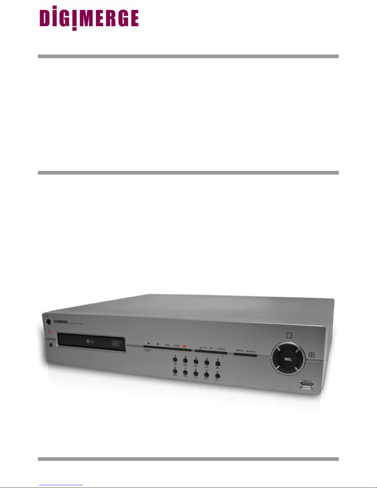
The DHU500 Series line of Pentaplex Network DVR’s offer a full-featured Networkable
video recording solution. Record in Real Time with 120 fps recording capability.
Images can be easily transferred using the built in CDRW optical drive or USB flash
drive. The system can be viewed and controlled over the internet from a remote
location with a password protected browser-based application. Easy access via the
Free Digimerge DDNS Service is included.
To learn more about this DHU500 Series DVR, and to learn about our complete range
of accessory products, please visit our website at:
http://www.digimerge.com
CAUTION
RISK OF ELECTRIC SHOCK
DO NOT OPEN
CAUTION: TO REDUCE THE RISK OF ELECTRIC SHOCK
DO NOT REMOVE COVER (OR BACK).
NO USER SERVICEABLE PARTS INSIDE.
REFER SERVICING TO A QUALIFIED SERVICE PERSONNEL
The lightning flash with arrowhead symbol, within an
equilateral triangle, is intended to alert the user to the
presence of uninsulated “dangerous voltage” within the
product’s enclosure that may be of sufficient magnitude
to constitute a risk of electric shock to persons.
The exclamation point within an equilateral triangle is
intended to alert the user to the presence of important
operating and maintenance (servicing) instructions in
the literature accompanying the appliance.
WARNING: TO PREVENT FIRE OR SHOCK HAZARD,
DO NOT EXPOSE THIS UNIT TO RAIN OR MOISTURE.
CAUTION: TO PREVENT ELECTRIC SHOCK, MATCH WIDE BLADE
ii
OF PLUG TO WIDE SLOT, FULLY INSERT.
Page 3
Important Safeguards
Important Safeguards
In addition to the careful attention devoted to quality standards in the manufacture process of your video
product, safety is a major factor in the design of every instrument. However, safety is your responsibility too.
This sheet lists important information that will help to assure your enjoyment and proper use of the video
product and accessory equipment. Please read them carefully before operating and using your video product.
Installation
1. Read and Follow Instructions - All the safety and
operating instructions should be read before the
video product is operated. Follow all operating
instructions.
2. Retain Instructions - The safety and operating
instructions should be retained for future reference.
3. Heed Warnings - Comply with all warnings on the
video product and in the operating instructions.
4. Polarization - Do not defeat the safety purpose of
the polarized or grounding-type plug.
A polarized plug has two blades with
one wider than the other.
A grounding type plug has two blades
and a third grounding prong.
The wide blade or the third prong are
provided for your safety.
If the provided plug does not fit into
your outlet, consult an electrician for
replacement of the obsolete outlet
5. Power Sources - This video product should be
operated only from the type of power source
indicated on the marking label. If you are not sure of
the type of power supply to your location, consult
your video dealer or local power company. For video
products intended to operate from battery power, or
other sources, refer to the operating instructions.
6. Overloading - Do not overload wall outlets of
extension cords as this can result in the risk of fire
or electric shock. Overloaded AC outlets, extension
cords, frayed power cords, damaged or cracked wire
insulation, and broken plugs are dangerous. They
may result in a shock or fire hazard. Periodically
examine the cord, and if its appearance indicates
damage or deteriorated insulation, have it replaced
by your service technician.
7. Power-Cord Protection - Power supply cords should
be routed so that they are not likely to be walked on
or pinched by items placed upon or against them,
paying particular attention to cords at plugs,
convenience receptacles, and the point where they
exit from the video product.
8. Ventilation - Slots and openings in the case are
provided for ventilation to ensure reliable operation
of the video product and to protect it from
overheating. These openings must not be blocked
or covered. The openings should never be blocked
by placing the video equipment on a bed, sofa, rug,
or other similar surface. This video product should
never be placed near or over a radiator or heat
register. This video product should not be placed in
a built-in installation such as a bookcase or rack
unless proper ventilation is provided or the video
product manufacturer’s instructions have been
followed.
9. Attachments - Do not use attachments unless
recommended by the video product manufacturer as
they may cause a hazard.
10. Water and Moisture - Do not use this video product
near water. For example, near a bath tub, wash bowl,
kitchen sink or laundry tub, in a wet basement, near
a swimming pool and the like.
Caution: Maintain electrical safety. Powerline
operated equipment or accessories connected to
this unit should bear the UL listing mark of CSA
certification mark on the accessory itself and should
not be modified so as to defeat the safety features.
This will help avoid any potential hazard from
electrical shock or fire. If in doubt, contact qualified
service personnel.
11. Accessories - Do not place this video equipment
on an unstable cart, stand, tripod, or table. The video
equipment may fall, causing serious
damage to the video product. Use
this video product only with a cart,
stand, tripod, bracket, or table
recommended by the
manufacturer or sold with the video
product. Any mounting of the product
should follow the manufacturer’s
instructions and use a mounting accessory
recommended by the manufacturer.
iii
Page 4

Important Safeguards
Service
13. Servicing - Do not attempt to service this video
equipment yourself as opening or removing covers
may expose you to dangerous voltage or other
hazards. Refer all servicing to qualified service
personnel.
14. Conditions Requiring Service - Unplug this video
product from the wall outlet and refer servicing to
qualified service personnel under the following
conditions.
A. When the power supply cord or plug is
damaged.
B. If liquid has been spilled or objects have fallen
into the video product.
C. If the video product has been exposed to rain
or water.
D. If the video product does not operate normally
by following the operating instructions. Adjust
only those controls that are covered by the
operating instructions. Improper adjustment of
other controls may result in damage and will often
require extensive work by a qualified technician
to restore the video product to its normal
operation.
E. If the video product has been dropped or the
cabinet has been damaged.
Use
19. Cleaning - Unplug the video product from the wall
outlet before cleaning. Do not use liquid cleaners or
aerosol cleaners. Use a damp cloth for cleaning.
20. Product and Cart Combination - Video and cart
combination should be moved with care. Quick
stops, excessive force, and uneven surfaces may
cause the video product and car combination to
overturn.
21. Object and Liquid Entry - Never push objects for
any kind into this video product through openings as
they may touch dangerous voltage points or
“short-out” parts that could result in a fire or electric
shock. Never spill liquid of any kind on the video
product.
22. Lightning - For added protection for this video
product during a lightning storm, or when it is left
unattended and unused for long periods of time,
unplug it from the wall outlet and disconnect the
antenna or cable system. This will prevent damage
to the video product due to lightning and power line
surges.
F. When the video product exhibits a distinct
change in performance. This indicates a need for
service.
15. Replacement Parts - When replacement parts are
required, have the service technician verify that the
replacements used have the same safety
characteristics as the original parts. Use of
replacements specified by the video product
manufacturer can prevent fire, electric shock or other
hazards.
16. Safety Check - Upon completion of any service or
repairs to this video product, ask the service
technician to perform safety checks recommended
by the manufacturer to determine that the video
product is in safe operating condition.
17. Wall or Ceiling Mounting - The cameras provided
with this system should be mounted to a wall or
ceiling only as instructed in this guide, using the
provided mounting brackets.
18. Heat - The product should be situated away from
heat sources such as radiators, heat registers,
stoves, or other products (including amplifiers) that
produce heat.
iv
Page 5

General Precautions
NOTE
This equipment has been certified and found to comply with the limits regulated by FCC, EMC, and LVD. Therefore, it
is designated to provide reasonable protection against interference and will not cause interference with other appliance
usage.
However, it is imperative that the user follows this manuals guidelines to avoid improper usage which may result in
damage to the unit, electrical shock and fire hazard injury
In order to improve the feature functions and quality of this product, the specifications are subject to change without
notice from time to time.
FCC CLASS B NOTICE
Note:
This equipment has been tested and found to comply with the limits for a Class B digital device, pursuant to Part
15 of the FCC Rules. These limits are designed to provide reasonable protection against harmful interference in
a residential installation. This equipment generates, uses, and can radiate radio frequency energy and, if not installed and used in accordance with the instruction, may cause harmful interference to radio communications.
However, there is no guarantee that interference will not occur in a particular installation. If this equipment does
cause harmful interference to radio or television reception (which can be determined by turning the equipment on
and off), the user is encouraged to try to correct the interference by one or more of the following measures:
z Reorient or relocate the receiving antenna
z Increase the separation between the equipment and receiver
z Connect the equipment into an outlet on a circuit different from that to which the receiver is
connected
z Consult the dealer or an experienced radio or television technician for assistance
General Precautions
1. All warnings and instructions of this manual should be followed
2. Remove the plug from the outlet before cleaning. Do not use liquid aerosol detergents. Use a water dampened cloth
for cleaning
3. Do not use this unit in humid or wet places
4. Keep enough space around the unit for ventilation. Slots and openings in the storage cabinet should not be blocked
5. During lightning storms, or when the unit is not used for a long time, disconnect the power supply, antenna, and cables
to protect the unit from electrical surge
DIGIMERGE TECHNOLOGIES INC.
http://www.digimerge.com
v
Page 6

DHU500 Series DVR Features
DHU500 Series DVR Features
Technology
• Embedded LINUX OS
• Total maximum recording rate 120 fps
• High-resolution & high-quality MPEG-4 algorithm
• Uses Watermarking & scrambling technologies
• Strong protection recorded data
• MPEG-4: 1 ~ 2 Kbytes per image with resolution 360x240
• Pentaplex network system: simultaneous local playback, view, record plus network view and playback
• CDRW optical drive and USB port for transferring critical images
• VGA Output (available only on 8 Ch & 16 Ch systems)
• Integrated video motion detection
Functionality
• Variable recording functions (Normal, Alarm, Motion and Schedule)
• Full channel real-time monitoring
• Live monitoring, recording, playback, backup and remote access at the same time
• Multi channel playback
• Variable event notification to e-mail, buzzer or PC Client system
• Network view & control via browser based application - Several remote DVR's can be controlled by
Web browser (PC Client System)
• Supports up to 1 TB internal data storage
• Adjustable video quality settings
• Quick multiple search by date/time, alarm or full list
• Security password protection
Convenience & Stability
• User-friendly UI (Text Based User Interface)
• Easy-to-use menu composition
• Easy-to-use recorded data search (Time, Date, Motion and Alarm)
• Auto restart after power interruption
• DB structure offers data stabilization and best storage utilization
vi
Page 7

Table of Contents
Table of Contents
Getting Started .......................................................................................... 9
DHU500 Series - Front ...................................................................... 10-11
DHU500 Series - Back ....................................................................... 12-13
Remote Control ....................................................................................... 14
Starting the DVR - Self Test Screens ..................................................... 15
Starting the DVR - QUAD Display ........................................................... 15
Powering Off the DVR/Stopping Recording ............................................ 15
Main Menu Control .................................................................................. 16
Main Menu Tree ...................................................................................... 17
Display Set .............................................................................................. 18
Display Set Menu Tree .............................................................................................................. 18
Camera Covert .......................................................................................................................... 19
Camera Name ........................................................................................................................... 19
OSD ON/OFF Covert ................................................................................................................. 20
Set Display Sequence ............................................................................................................... 20
Event Clear ................................................................................................................................ 21
Recording Set ......................................................................................... 22
Recording Set Menu Tree .................................................................................................... 22-23
Global Parameters ..................................................................................................................... 24
Normal Recording...................................................................................................................... 24
Alarm Recording ........................................................................................................................ 25
Motion Recording ...................................................................................................................... 26
Schedule Recording .................................................................................................................. 28
Recording ON/OFF .................................................................................................................... 29
System Set .............................................................................................. 30
Recording Set Menu Tree ......................................................................................................... 30
Basic .......................................................................................................................................... 31
Disk Format ............................................................................................................................... 32
Password Change ..................................................................................................................... 32
Client Account ........................................................................................................................... 33
Program Update ........................................................................................................................ 33
PTZ Menu .................................................................................................................................. 34
Network Set ............................................................................................ 35
DDNS Set .................................................................................................................................. 35
IP Set ......................................................................................................................................... 36
Event Notification ............................................................................... 37-38
Email Registration ..................................................................................................................... 38
Email Report .............................................................................................................................. 38
Notification Out .......................................................................................................................... 39
Event Search Function ............................................................................ 40
Date / Time Search .................................................................................................................... 41
Calendar Search ........................................................................................................................ 41
Backup Menu ............................................................................................................................. 42
Log View .................................................................................................................................... 43
7
Page 8

Table of Contents
USB - Updating the DVR Firmware ........................................................ 44
Compatible USB Devices .......................................................................................................... 44
Network Connectivity .............................................................................. 45
DVR Network Settings ............................................................................ 46
Finding Your External IP Address ............................................................................................. 46
Router Port Forwarding ........................................................................... 47
Setting Up Your DDNS Account ............................................................. 48
Setting up DDNS on the DVR ................................................................. 50
Accessing the DVR Locally / Remotely with a PC .................................. 51
Internet Explorer Settings - Active X Controls ........................................................................... 51
Internet Explorer Settings - Allowing Pop-Ups .......................................................................... 52
Web Client Software ............................................................................... 53
Minimum System Requirements: ............................................................................................... 53
Logging Into Live Monitoring ..................................................................................................... 53
Web Client - Main Window ...................................................................... 54
Channels Window ...................................................................................................................... 55
Detail Tabs ................................................................................................................................ 55
Remote/Local Controls ......................................................................................................... 55-56
System ....................................................................................................................................... 56
Remote/Local Controls .............................................................................................................. 57
Local .......................................................................................................................................... 57
Save Controls ............................................................................................................................ 58
Live ............................................................................................................................................ 59
Disconnect ................................................................................................................................. 59
Pan/Tilt/Zoom ............................................................................................................................ 59
Display Options ......................................................................................................................... 60
Connect Button .......................................................................................................................... 60
Setup ......................................................................................................................................... 60
Remote Setup ............................................................................................................................ 60
Local Setup ................................................................................................................................ 66
Firmware Upgrade ..................................................................................................................... 67
Channel Buttons ........................................................................................................................ 67
Date / Time ................................................................................................................................ 67
Troubleshooting ................................................................................. 68-69
DVR Specifications - Appendix #1 .......................................................... 70
Connecting Motion / Alarm Device - Appendix #2 .................................. 71
8
Page 9
Getting Started
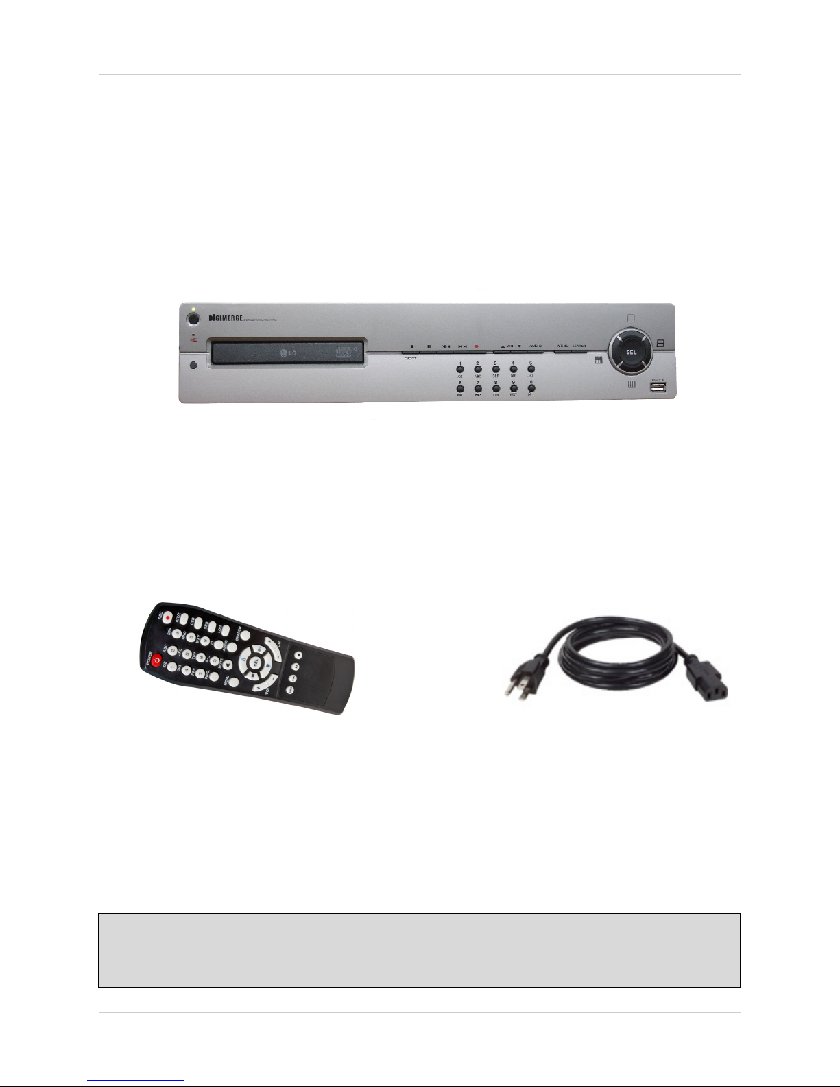
The DHU500 Series comes with the following components:
DHU500 SERIES DVR
Getting Started
REMOTE CONTROL
CHECK YOUR PACKAGE TO CONFIRM THAT YOU HAVE RECEIVED THE COMPLETE
SYSTEM, INCLUDING ALL COMPONENTS SHOWN ABOVE.
POWER CABLE
9
Page 10

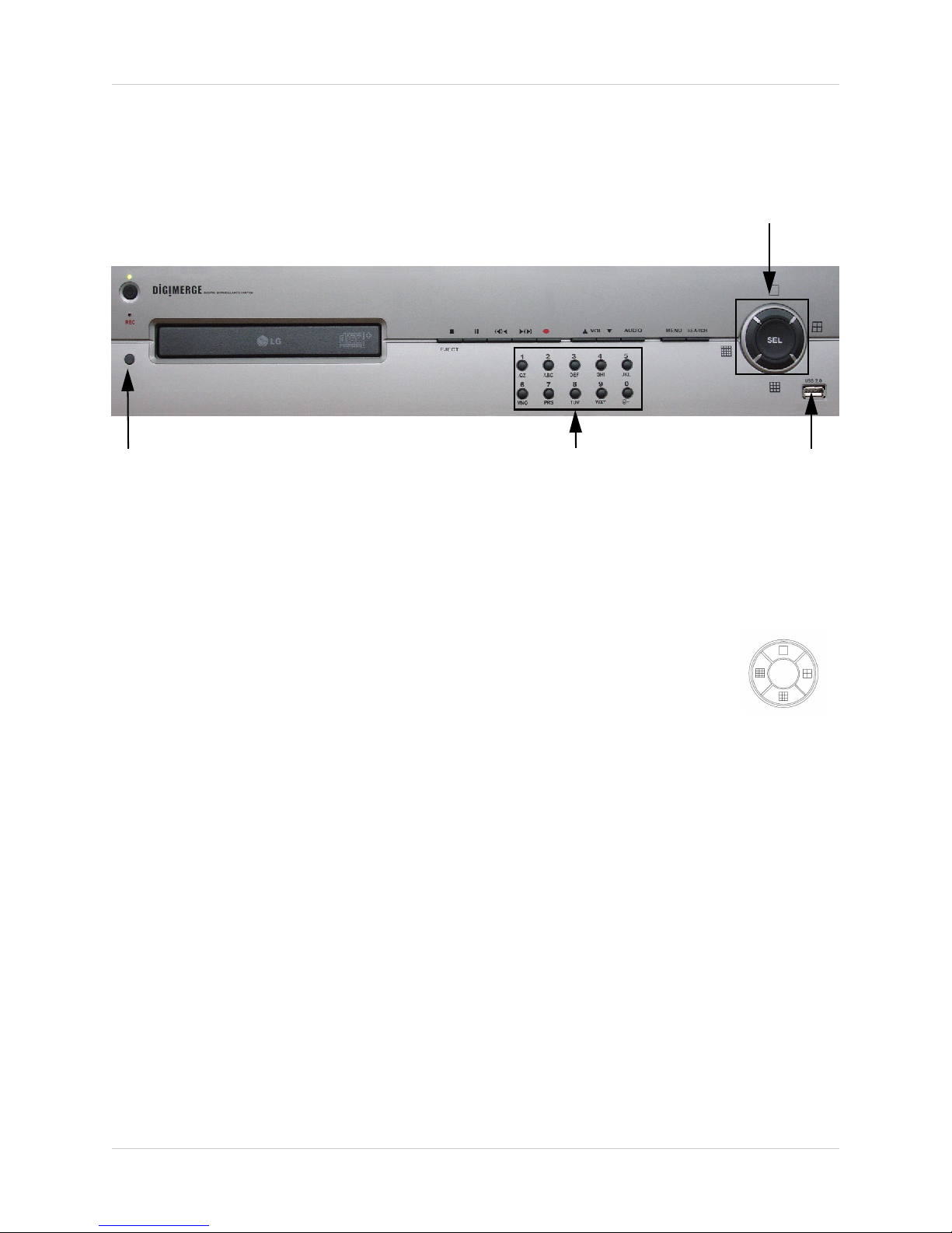
DHU500 Series - Front
DHU500 Series - Front
12 34567
13 14 15
1. POWER - Turns the DVR unit ON/OFF.
9
8
10
11
12
2. CDRW DRIVE - Drive bay for CD-RW Drive
3. STOP / EJECT - Stops the playback of a previously recorded event / Ejects the CDRW Drive.
4. PAUSE - Pauses the playback of a previously recorded event.
5. REV - REVERSES the playback of a previously recorded event.
6. PLAY/FWD - Starts the playback of a previously recorded event. If the PLAY/FF button is pressed
during playback, the FAST FORWARD option will become active.
7. REC - Manually starts/stops recording of the currently displayed camera.
8. VOLUME UP / DOWN - Raises and Lowers the system volume.
9. AUDIO - Switches between cameras 1-4 to receive audio
* Only one channel audio available on the 4-Channel DVR Model.
10. MENU - Accesses the DVR system menu options. See page 16 for details.
11. SEARCH - Accesses the Search Menu. See page 40 for Search Menu options
10
Page 11
DHU500 Series - Front
12
13 14 15
12. SCREEN SELECT / MENU NAVIGATION - Performs a dual purpose:
• Changes the Camera view to Single, 4 Camera, 9 Camera or 16 Camera views.
• Use the
KLIJ buttons to navigate through the MENU options (in MENU
mode).
13. IR RECEIVER - Used to receive a signal from a Remote Control
14. NUMBER / LETTER PAD
• Use the numbers to switch between cameras in View mode.
• Use the Numbers and Letters for Menu data input.
15. USB PORT - Connection port for a removable USB Hard Drive (USB Key)
11
Page 12
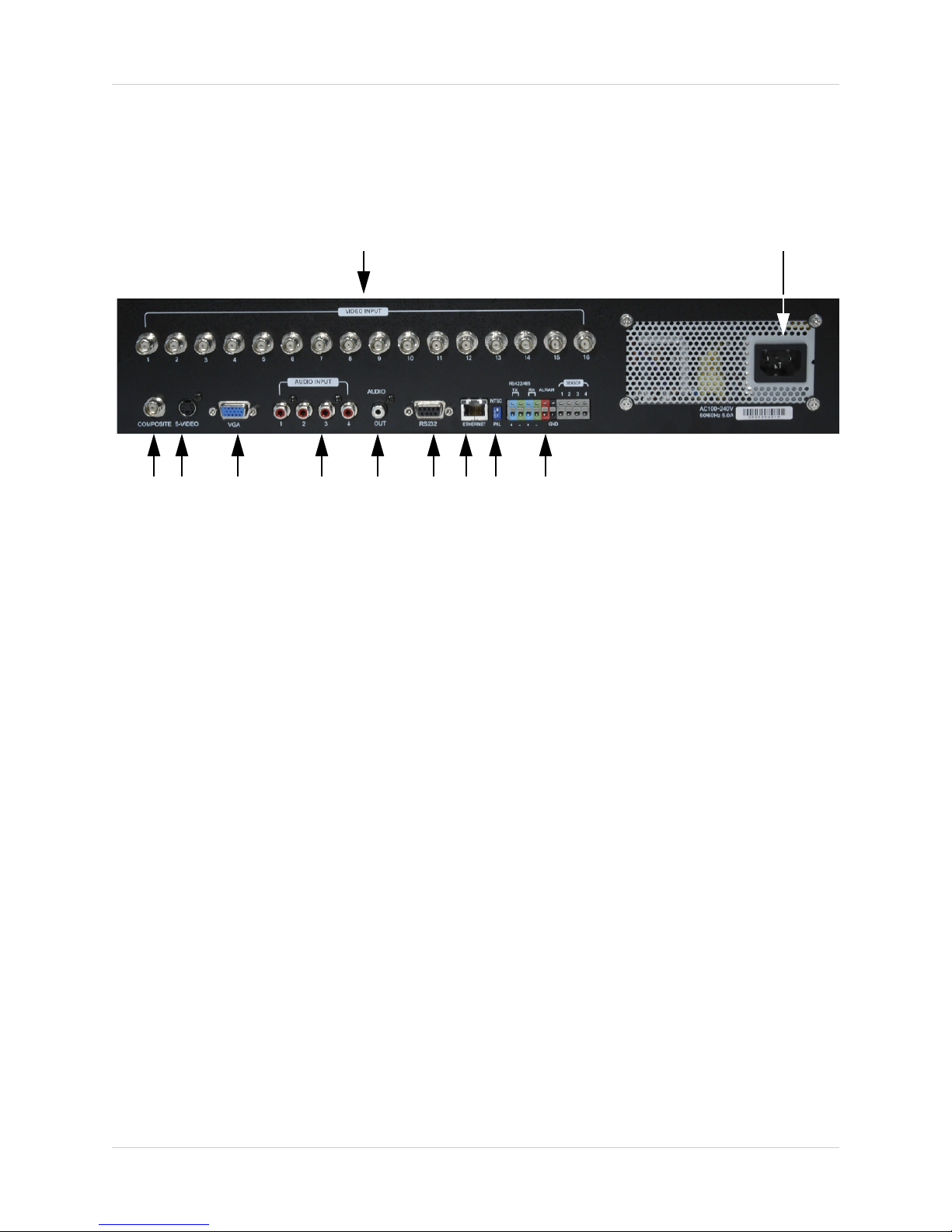
DHU500 Series - Back
DHU500 Series - Back
12
345 678
1. BNC VIDEO INPUTS - Video inputs for direct connection to Cameras or for looping input to a
DVR. The number of ports will vary based on the DVR model (4 Channel, 8 Channel or 16
Channel).
2. AC INPUT - Connect the AC power using the power cord provided with the unit from the DVR
to an electrical outlet.
3. COMPOSITE - A Composite Video OUT connection used to connect the DVR to a Slave Monitor
or DVR.
4. S-VIDEO - Outgoing connection for S-VIDEO.
5. VGA PORT - Used to connect the DVR to a computer Monitor.
* Not available on 4-Channel DVR Model.
910 11
6. AUDIO INPUTS - Connect up to 4 camera Audio inputs.
12
Page 13

7891011
DHU500 Series - Back
7. AUDIO OUT - Connect the Audio OUT to the AUDIO IN on an DVR or Monitor.
8. RS232 PORT - Connection for an RS-232 Device.
* Not available on 4-Channel DVR Model.
9. ETHERNET PORT - Connects the DVR to a router for connection to the internet. Refer to the
Instructions on Page 51 for Remote Connection.
10. NTSC/PAL SWITCH - Changes the DVR unit between NTSC and PAL modes.
11. ALARM / SENSOR BLOCK - Ports for connecting an Alarm or Sensor Device (such as a
Motion Sensor or Window/Door Sensor).
13
Page 14

Remote Control
Remote Control
Listed below is a quick reference for the Remote Control. For details on specific features, refer to
the DHU500 Series - Front Panel features on Pages 10-11
POWER BUTTON Turns the DVR ON
NUMBER PAD Control for Cameras
1-16 & used for
adding information in
the Menu system.
INFO - Displays
system details
MUTE - Turns sound
ON/OFF
MENU - Accesses the
DVR Menu System
REC - Starts/Stops
Manual Recording
PTZ - Accesses the
Pan/Tilt/Zoom Setup
menu
OSD - Configures the
On Screen Display
settings
SEQ - Sets camera
display to Sequence
LOG - View system
log details
AUDIO - Switches the
current Audio Channel
(only one audio
channel on the 4
Channel DVR model)/
SEL / CONTROLS Switch between
display modes
(Single, Quad, 9 and
16). SEL used as the
Select function in the
Menu.
VOL - Adjusts the
Volume UP/DOWN
NOTE - Remote Control may not be exactly as shown - color may vary.
14
SEARCH - Accesses
the Search Menu.
CH -/+ - Switches
between Channels
PLAYBACK
CONTROLS -
Controls the playback
of a previously
recorded event
Page 15
Starting the DVR - Self Test Screens
Starting the DVR - Self Test Screens
Once the DVR has been connected and powered on, the following self-test screens will appear:
LOADING PROGRAMS ......
CHECKING HDD INTEGRITY ......
INITIALIZING DEVICES ...
NOTE: If a new HARD DRIVE is detected by the system, the DVR will automatically FORMAT
the new drive.
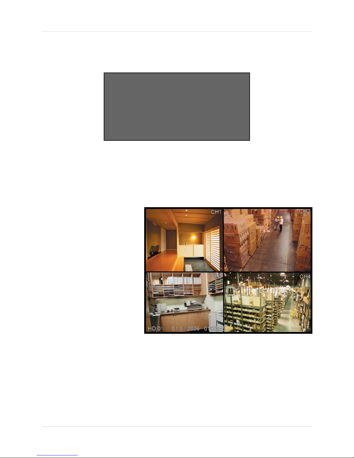
Starting the DVR - QUAD Display
After the system self-tests have
been completed, the DVR will
switch to the CAMERA viewing
screens (in QUAD MODE) with the
following information displayed on
screen:
• CH1-CH4: Camera title
indicators
• HDD%: Percentage of Hard
Drive used
• MM/DD/YYYY - HH:MM:SS:
The current system date and
time.
If a camera is not detected, or the
Camera is in COVERT MODE, the
associated portion of the QUAD or
MULTI screen will display a BLUE SCREEN.
Powering Off the DVR/Stopping Recording
In order to power down the DVR Unit, or to manually stop the current recording, the default
system password of ‘00000000’ will need to be entered (when prompted). If the default password
is changed, then the new user specified password will be used instead.
15
Page 16

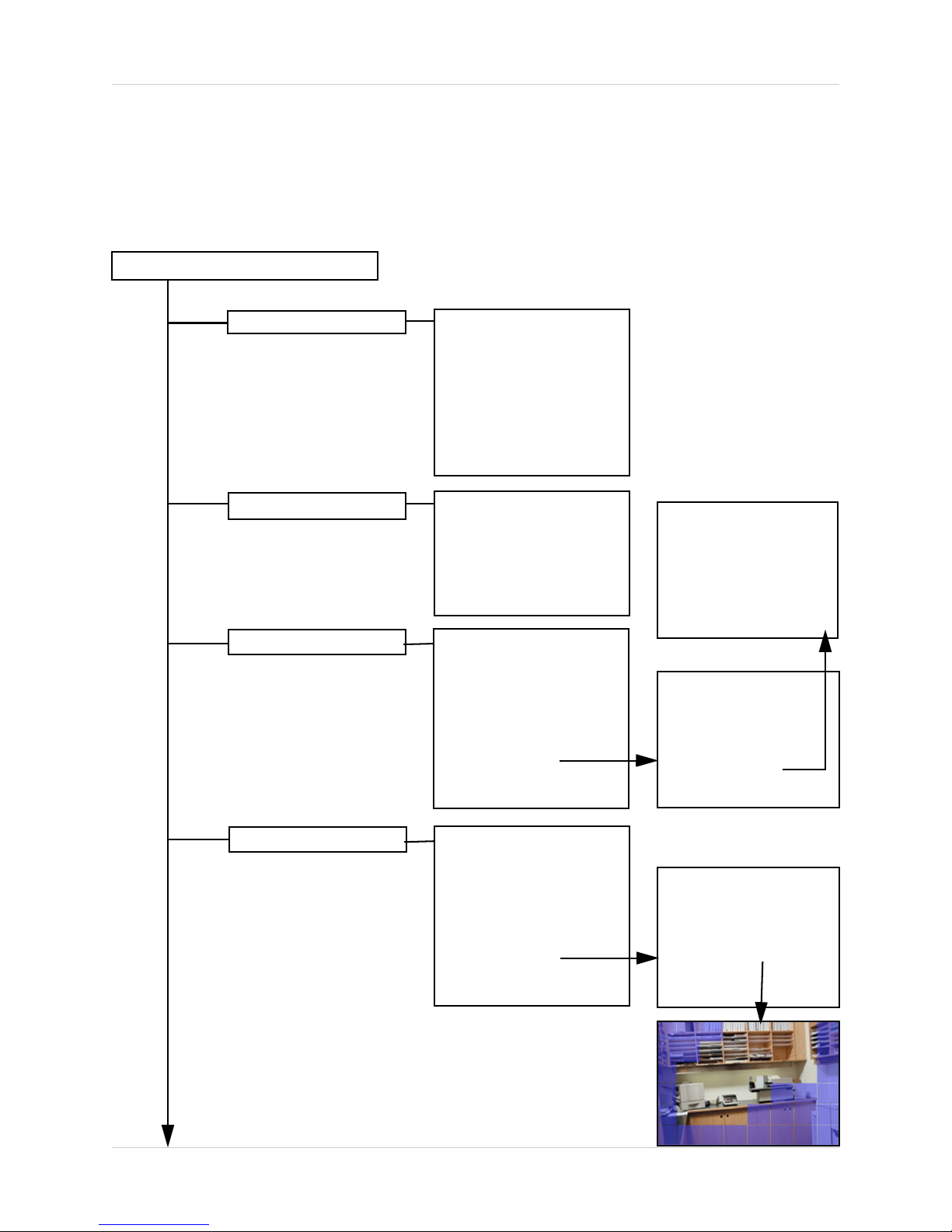
Main Menu Control
Main Menu Control
• Enter the MENU screen by pressing the MENU button. The System Password may be required,
based on system settings.
• Scroll through the 5 Main options by pressing the KL buttons.
• To enter a sub-menu, navigate to the option and press the SEL button.
• To exit a SUBMENU, press the MENU button. To save the changes, select the SAVE & EXIT
option and press the SEL button.
• Pressing the MENU button from the MAIN MENU will exit the MENU configuration screen
Outlined below are the buttons used to access menu settings:
KLIJ
SEL
MENU
: Scroll up and down within a menu option / Change menu options
: Press this button to select and change the values in a menu option
: Complete modifications of a menu option; exit a menu
NOTE:
After 60 seconds of inactivity in the Menu mode, the system will go back to the previously
displayed live camera screen
DISPLAY SET
RECORDING SET
SYSTEM SET
NETWORK SET
EVENT NOTIFICATION
Set the display options
Set the Recording options
Set the System options
Set the Network Options
Setup for Event Notifications
through Email
MAIN MENU
DISPLAY SET
RECORDING SET
SYSTEM SET
NETWORK SET
EVENT NOTIFICATION
16
Page 17

Main Menu Tree
Main Menu
Main Menu Tree
Display Set
Recording Set
System Set
Monitor Adjustment
Camera Covert
Camera Name
OSD ON/OFF
Set Display Sequence
Event Clear
Global Parameter
Normal Recording
Alarm Recording
Motion Recording
Schedule Recording
Recording ON/OFF
Basic
Disk Format
Password Change
Client Account
Program Update
Auto Delete
PTZ
(4 CH Only)
(8/16 CH Only)
(8/16 CH Only)
Network Set
Event Notification
DDNS Set
IP Set
E-Mail Registration
E-Mail Report
Notification Out
17
Page 18

Display Set
Display Set
This submenu allows you to change the DISPLAY options for the DVR unit and any connected
cameras. Selecting options on this Menu will access additional settings and options.
Display Set Menu Tree
Display Set
Monitor Adjustment
(4 CH Only)
Camera Covert
Camera Name
OSD ON/OFF
Left Key = Move Left
Right Key = Move Right
Down Key = Move Down
Up Key = Move Up
Sel Key = Save & Exit
Page:
Camera 1:
Camera 2:
Camera 3:
Camera 4:
Save & Exit
Page:
Camera 1:
Camera 2:
Camera 3:
Camera 4:
Save & Exit
OSD:
Save & Exit
1
OFF
OFF
OFF
OFF
1
CH1
CH2
CH3
CH4
ON
Set Display Sequence
(8/16 CH Only)
Event Clear
18
Full Display Sequence
Quad Display Seq.
Start Full Display Seq
Start Quad Display Seq
Page:
Camera 1:
Camera 2:
Camera 3:
Camera 4:
Save & Exit
Page 1 SEQ:
Page 2 SEQ:
Save & Exit
1
OFF
OFF
OFF
OFF
BYPASS
BYPASS
Page 19

Display Set
Display Set
Monitor Set (4 CH only)
Allows the attached monitor horizontal and vertical positioning to be adjusted. Use the arrows to
adjust the screen left/right and up/down. Press the SEL button to Save and Exit.
Camera Covert
Camera Covert
Turns Camera display ON/OFF The DVR
unit will continue to record, even if all
cameras are set to OFF.
NOTE: The number of cameras displayed
will change based on the Model of DVR - 4,
8 or 16 Cameras are available.
1. PAGE: Displays up to 8 camera configurations per page (second page only available for 16
camera setups). To change the page, press the
SEL button to change to Page 2.
2. CAMERA 1 - CAMERA #: Turn the Camera display ON/OFF. To change the camera setting,
press the
3. SAVE & EXIT: Saves any changes made, and exits to the Main Menu. Press the
to highlight, and press the SEL button to accept the changes.
K and L buttons to highlight, and press the ←→ buttons to change to ON/OFF.
K and L buttons to highlight, and press the
Page:
Camera 1:
Camera 2:
Camera 3:
Camera 4:
Save & Exit
K and L buttons
1
OFF
OFF
OFF
OFF
Camera Name
Camera names can be set up using this
menu.
NOTE: The number of cameras displayed
will change based on the Model of DVR - 4,
8 or 16 Cameras are available.
1. PAGE: Displays up to 8 camera configurations per page (second page only available for 16
camera setups). To change the page, press the
SEL button to change to Page 2.
2. CAMERA 1 - CAMERA #: Change the name for the Cameras. To change the camera setting,
press the
symbol will appear. Use the NUMBER PAD and I and J buttons on the front of the DVR
to change the name (A-Z, 0-9) to a maximum of 8 characters. Press the SEL button to accept
the change.
3. SAVE & EXIT: Saves any changes made, and exits to the Main Menu. Press the
to highlight, and press the SEL button to accept the changes.
K and L buttons to highlight, and press the SEL button to select a camera - a flashing
Camera Name
K and L buttons to highlight, and press the
Page:
Camera 1:
Camera 2:
Camera 3:
Camera 4:
Save & Exit
K and L buttons
1
CH1
CH2
CH3
CH4
19
Page 20

Display Set
OSD ON/OFF Covert
Turns the information display/camera
names, hard drive usage, date and time)
ON/OFF.
1. OSD: Turns the ON SCREEN DISPLAY to ON/OFF. To change the setting, press the K and L
buttons to highlight, and press the ←→ buttons to switch between ON/OFF.
2. SAVE & EXIT: Saves any changes made, and exits to the Main Menu. Press the K and L buttons
to highlight, and press the SEL button to accept the changes.
OSD ON/OFF
OSD:
Save & Exit
ON
Set Display Sequence (8/16 CH Only)
Display Settings for Single or Quad display of the cameras (in Sequence Mode).
Set Display Sequence
Full Display Sequence
Page:
Camera 1:
Camera 2:
Camera 3:
Camera 4:
Save & Exit
1
10 SEC
BYPASS
BYPASS
BYPASS
Quad Display Sequence
Start Full Display Seq.
Start Quad Display Seq
NOTE: The number of cameras displayed on submenus will change based on the Model of DVR:
4, 8 or 16 Cameras are available.
20
Page 1 SEQ:
Page 2 SEQ:
Save & Exit
BYPASS
BYPASS
Page 21

Display Set
Set Display Sequence
1. FULL DISPLAY SEQUENCE: Set the length of time each camera is displayed in cycling Full
Screen Display mode:
• PAGE: Displays up to 8 camera configurations per page (second page only available for 16
camera setups). To change the page, press the
SEL button to change to Page 2.
• CAMERA 1 - CAMERA #: Set the length of time that a Camera is displayed in Sequence
Mode. To change the camera setting, press the
and J buttons on the front of the DVR to change the length of time a Camera is displayed.
Options include 5, 10, 15, 30, 45, 60 (in seconds) and Bypass.
K and L buttons to highlight, and press the
K and L buttons to highlight, and use the I
• SAVE & EXIT: Saves any changes made, and exits to the Main Menu. Press the
buttons to highlight, and press the SEL button to accept the changes.
2. QUAD DISPLAY SEQUENCE: Set the length of time each QUAD of cameras (4 cameras per
page) is displayed in cycling QUAD Display mode:
• PAGE # SEQ: Set the length of time that a QUAD of Cameras is displayed in Sequence. To
change the Page setting, press the
Page 2 (Cameras 5-8) etc. Use the I and J buttons on the front of the DVR to change the
length of time a Quad is displayed. Options include 5, 10, 15, 30, 45, 60 (in seconds) and
Bypass.
• SAVE & EXIT: Saves any changes made, and exits to the Main Menu. Press the
buttons to highlight, and press the SEL button to accept the changes.
3. START FULL DISPLAY SEQUENCE: Starts viewing Cameras in Full Screen Display Sequence
Mode (based on the settings configured in the FULL DISPLAY SEQUENCE menu).
4. START QUAD DISPLAY SEQUENCE: Starts viewing Cameras in QUAD Display Sequence
Mode (based on the settings configured in the QUAD DISPLAY SEQUENCE menu).
K and L buttons to highlight. Page 1 (Cameras 1-4),
K and L
K and L
Event Clear
Clears the listing of Previously Recorded Events on the DVR Hard Drive.
21
Page 22
Recording Set
Recording Set
This submenu allows you to change the RECORDING options for the DVR unit. Selecting options
on this Menu will access additional settings and options.
Recording Set Menu Tree
Recording Set (Enter Password)
Global Parameter
Normal Recording
Alarm Recording
Audio 1 Rec:
Audio 2 Rec:
Audio 3 Rec:
Audio 4 Rec:
Repeat Rec:
Watermark Emb
Rec Res
Save & Exit
CH/
CH1
CH2
CH3
CH4
Save & Exit
CH/
CH1
CH2
CH3
CH4
PostAlarm: 150 sec.
Setup Alarm
Save & Exit
FPS/
8
8
8
7
FPS/
8
8
8
7
720 x 480
QUALITY
HIGH
HIGH
MID
LOW
QUALITY
HIGH
MID
LOW
OFF
OFF
OFF
OFF
OFF
ON
ON
Sensor 1 Input:
Sensor 2 Input:
Sensor 3 Input:
Sensor 4 Input:
Alarm Out:
Save & Exit
Alarm 1:
Alarm 2:
Alarm 3:
Alarm 4:
Setup Sensor
Save & Exit
None
None
NC
NO
Off
1 2
3 4
5 6
7 8
Motion Recording
22
CH/
CH1
CH2
CH3
CH4
PostAlarm: 150 sec.
Setup Motion
Save & Exit
FPS/
8
8
8
7
QUALITY
HIGH
MID
LOW
OFF
CH/
CH1
CH2
CH3
CH4
Save & Exit
AREA/
AREA
AREA
AREA
AREA
SENSE
HIGH
MID
LOW
OFF
Page 23

Recording Set
Schedule Recording
Recording ON/OFF
CH/
CH1
CH2
CH3
CH4
FPS/
8
8
8
7
QUALITY
HIGH
MID
LOW
OFF
Setup Schedule
Save & Exit
Alarm Rec:
Motion Rec:
Schedule Rec:
Save & Exit
Schedule Setup Details
OFF
OFF
OFF
23
Page 24

Recording Set
Recording Set
Global Parameters
Settings for General Parameters.
1. AUDIO # REC: Turns Audio recording ON/OFF. press the K and L buttons to highlight, and
press the ←→ buttons to change to ON/OFF.
2. REPEAT RECORDING: Allows the DVR unit to repeat recording. To change the setting, press
the
K and L buttons to highlight, and press the ←→ buttons to change to ON/OFF.
3. WATERMARK EMBEDDING: Adds Watermarking to the recorded event. Press the K and L
buttons to highlight, and press the ←→ buttons to change to ON/OFF.
4. RECORDING RESOLUTION: Sets the Recording Resolution for events. To change the
Resolution, press the K and L buttons to highlight, and press the ←→ buttons to change to
either 720x240 or 360x240.
5. SAVE & EXIT: Saves any changes made, and exits to the Main Menu. Press the K and L buttons
to highlight, and press the SEL button to accept the changes.
Global Parameter
Audio 1 Rec:
Audio 2 Rec:
Audio 3 Rec:
Audio 4 Rec:
Repeat Rec:
Watermark Emb
Rec Res
Save & Exit
720 x 480
OFF
OFF
OFF
OFF
ON
ON
Normal Recording
Controls the settings for Manual Recording.
NOTE: The number of cameras displayed on submenus will change
based on the Model of DVR: 4, 8 or 16 Cameras are available.
1. CH1 - CH4: Lists all available cameras for configuration. Press the K and L buttons to highlight,
and press the
to change the settings, and press SEL to accept the changes:
• FPS: A set number of Frames Per Second (total) is divided between all available cameras
based on Resolution settings.
• QUALITY: Set the quality level for the recording - High, Mid or Low
2. SAVE & EXIT: Saves any changes made, and exits to the Main Menu. Press the K and L buttons
to highlight, and press the SEL button to accept the changes.
24
←→ buttons to select the FPS or Quality for each CH. Use theK and L buttons
Normal Recording
CH/
CH1
CH2
CH3
CH4
Save & Exit
FPS/
8
8
8
6
QUALITY
MID
MID
MID
MID
Page 25

Recording Set
Alarm Recording
Alarm Settings for the DVR.
Alarm Recording
CH/
CH1
CH2
CH3
CH4
FPS/
8
8
8
7
QUALITY
HIGH
MID
LOW
OFF
PostAlarm: 150 sec.
Setup Alarm
Save & Exit
Sensor 1 Input:
Sensor 2 Input:
Sensor 3 Input:
Sensor 4 Input:
Alarm Out:
Save & Exit
Alarm 1:
Alarm 2:
Alarm 3:
Alarm 4:
Setup Sensor
Save & Exit
Sensor 1:
Sensor 2:
Sensor 3:
Sensor 4:
Alarm Out:
Save & Exit
None
None
NC
NO
Off
1 2
3 4
5 6
7 8
None
None
NC
NO
Off
NOTE: The number of cameras, alarms and sensors displayed on submenus will change based
on the Model of DVR: 4, 8 or 16 Cameras are available.
1. CH1-CH4: Lists all available cameras for configuration. Press the K and L buttons to highlight,
and press the SEL button to select the CH#. Use the
I and J and SEL buttons to change the
FPS and Quality settings:
• FPS: A set number of Frames Per Second (total) is divided between all available cameras
based on Resolution settings.
• QUALITY: Set the quality level for the recording - High, Mid or Low.
2. POST ALARM: Set the duration that the alarm will continue once detected: 5, 30, 60, 90, 120,
150, 180, 210 or 240 seconds.
25
Page 26

Recording Set
3. SETUP ALARM: Configuration
sub-menus for Alarm and Sensors.
Press the
highlight, and press the SEL button
to access the Alarm Submenu. Use
I and J to choose the
the
cameras to be associated to each
alarm:
4. SETUP SENSOR: Configuration
for any Sensors attached to the
Alarm block. Press the
buttons to highlight, and press the
SEL button to access the Sensor
Submenu. Use the
the Sensor type: NO (Normally
Open), NC (Normally Closed) or
None.
5. SAVE & EXIT: Saves any changes
made, and exits to the Main Menu.
Press the
highlight, and press the SEL button
to accept the changes.
K and L buttons to
K and L
I and J to set
K and L buttons to
Alarm 1:
Alarm 2:
Alarm 3:
Alarm 4:
Setup Sensor
Save & Exit
1 2
3 4
5 6
7 8
Page: 1:
CH1:
CH2:
CH3:
CH4:
Save & Exit
Sensor 1:
Sensor 2:
Sensor 3:
Sensor 4:
Alarm Out:
Save & Exit
YES
YES
NO
NO
None
None
NC
NO
Off
Motion Recording
Setup and configurations for Motion Sensor events.
Motion Recording
NOTE: The number of cameras, alarms and sensors
displayed on submenus will change based on the
Model of DVR: 4, 8 or 16 Cameras are available.
CH/
CH1
CH2
CH3
CH4
PostMotion: 150 sec.
Setup Motion
Save & Exit
FPS/
8
8
8
7
QUALITY
HIGH
MID
LOW
OFF
CH/
CH1
CH2
CH3
CH4
Save & Exit
AREA/
AREA
AREA
AREA
AREA
SENSE
HIGH
MID
LOW
OFF
26
Page 27

Recording Set
Motion Recording
1. CH1 - CH4: Lists all available cameras for configuration. Press the K and L buttons to highlight,
and press the
to change the settings, and press SEL to accept the changes:
• FPS: A set number of Frames Per Second (total) is divided between all available cameras
based on Resolution settings.:
• QUALITY: Set the quality level for the recording - High, Mid, Low or Off
2. POST MOTION DURATION: Set the duration that the alarm will continue once detected: 5, 30,
60, 90, 120, 150, 180, 210 or 240 seconds.
3. SETUP MOTION: Configuration for each Motion Sensor enabled Camera Press the K and L
buttons to highlight the Setup Motion option, and press the SEL button to access the SETUP
MOTION submenu. Press the
SEL button to select.
• AREA: Press the SEL button on the AREA option to specify segments of the Camera view
to have Motion Detection. Use the KLIJ buttons to
navigate around the Motion Setup screen, and press
the SEL button to turn a segment ON/OFF. Press the
MENU button once complete. Dark Blue indicates that
a section has been selected for motion detection, and
blank areas indicate that motion will not be detected
in those areas.
←→ buttons to select the FPS or Quality for each CH. Use theK and L buttons
K and L buttons to highlight a specific Camera, and press the
• SENSE: Sets the Sensitivity of the Motion Detection:
Use the
setting to High, Mid, Low or Off.
4. SAVE & EXIT: Saves any changes made, and exits to the Main Menu. Press the K and L buttons
to highlight, and press the SEL button to accept the changes.
I and J and SEL buttons to change the
27
Page 28

Recording Set
Schedule Recording
Setup and configurations for Scheduled events.
Schedule Recording
CH/
CH1
CH2
CH3
CH4
Setup Schedule
FPS/
8
8
8
7
QUALITY
HIGH
MID
LOW
OFF
Schedule Setup Details
Save & Exit
NOTE: The number of cameras, alarms and sensors displayed on submenus will change based
on the Model of DVR: 4, 8 or 16 Cameras are available.
1. CH1 - CH4: Lists all available cameras for configuration. Press the K and L buttons to highlight,
and press the ←→ buttons to select the FPS or Quality for each CH. Use theK and L buttons
to change the settings, and press SEL to accept the changes:
• FPS: A set number of Frames Per Second (total) is divided between all available cameras
based on Resolution settings.
• QUALITY: Set the quality level for the recording - High, Mid, Low
2. SETUP SCHEDULE: Settings for scheduled recording times. Press the K and L buttons to
highlight, and press the SEL button to access the Schedule Setup Submenu:
• Use the K and L to choose a day (SUN-SAT) and
SEL to set the schedule.
• Use the
KLIJ buttons to set the recording Start
Time and End Time
• Select SAVE & EXIT to return to the Menu
SUN
MON
TUE
WED
THU
FRI
SAT
FROM
00:00
00:00
00:00
00:00
00:00
00:00
00:00
TO
00:00
00:00
00:00
00:00
00:00
00:00
00:00
FROM
00:00
00:00
00:00
00:00
00:00
00:00
00:00
TO
00:00
00:00
00:00
00:00
00:00
00:00
00:00
Save & Exit
3. SAVE & EXIT: Saves any changes made, and exits to the Main Menu. Press the K and L buttons
to highlight, and press the SEL button to accept the changes.
28
Page 29

Recording ON/OFF
Controls the Recording for Event Types.
Recording Set
Recording ON/OFF
ALARM RECORDING: Turns Alarm Recording ON/OFF. Press the K and L buttons to highlight,
and press the
MOTION RECORDING: Turns Motion Recording ON/OFF. Press the K and L buttons to
highlight, and press the
SCHEDULE RECORDING: Turns Schedule Recording ON/OFF. Press the K and L buttons to
highlight, and press the
SAVE & EXIT: Saves any changes made, and exits to the Main Menu. Press the K and L
buttons to highlight, and press the SEL button to accept the changes.
←→ buttons to switch between ON and OFF.
←→ buttons to switch between ON and OFF.
←→ buttons to switch between ON and OFF.
Alarm Rec:
Motion Rec:
Schedule Rec:
Save & Exit
OFF
OFF
OFF
29
Page 30

System Set
System Set
This submenu allows you to change the SYSTEM options for the DVR unit. Selecting options on
this Menu will access additional settings and options.
Recording Set Menu Tree
System Set
Basic
Disk Format
Password Change
Client Account
Program Update
Language
Initialization
Date Format
Date/Time
Information
Save & Exit
Internal HDD
External HDD
Execute Format
New Password:
Confirm Password
Exit w/o Registering
PASSWORD MISMATCH
Add New Account
Delete Account
Save & Exit
English
MM-DD-YYYY
01-15-2006
NO
NO
User ID
Password
Confirm Password
Exit without Register
(no input)
Auto Delete Set
PTZ (enter Password)
(8/16 CH Only)
30
Period: 99 Days
Save & Exit
Pan/Tile/Zoom
Focus
Setup
Save & Exit
Page 31

System Set
System Set
Basic
Settings for General Parameters.
1. LANGUAGE: Displays the current default language on the DVR (English). This option cannot
be changed.
2. INITIALIZATION: Resets all settings to Factory Default. To change the setting, press the K and
Basic
Language
Initialization
Date Format
Date/Time
Information
Save & Exit
English
MM-DD-YYYY
01-15-2006
L buttons to highlight, and press the SEL button. A message will appear prompting for User input:
All setup will be returned to Factory Default
• Press the Select key to continue
• Press the Menu key to exit
3. DATE FORMAT: Configuration for the date display on the DVR. Press the K and L buttons to
highlight, and press the IJ to change the date format:
• MM-DD-YYYY
• DD-MM-YYYY
• YYYY-MM-DD
4. DATE/TIME: Sets the Date and Time for the unit. Press the K and L buttons to highlight, and
press the SEL key to enter the configuration. Press the KLIJ buttons to change the date format.
5. INFORMATION: Displays System Information:
HDD Capacity:
FPGA Version:
Application:
RAMDisk Version:
Kernel Version:
IP Address:
MAC Address
6. SAVE & EXIT: Saves any changes made, and exits to the Main Menu. Press the K and L buttons
to highlight, and press the SEL button to accept the changes.
## GB / ## GB
############
############
############
############
###.###.###.###
##:##:##:##:##:##
31
Page 32

System Set
Disk Format
Displays Hard Drive information.
Disk Format
Internal HDD
External HDD
NO
NO
Execute Format
1. INTERNAL HDD: Allows the user to format the HDD. Use the IJ to change this option to YES
or NO. To format the Drive, set this option to YES and select the EXECUTE FORMAT option.
2. EXTERNAL HDD: Allows the user to format the External HDD. Use the IJ to change this
option to YES or NO. To format the Drive, set this option to YES and select the EXECUTE
FORMAT option.
3. EXECUTE FORMAT: Allows the Hard Drive to be formatted. Press the K and L buttons to
highlight, and press the SEL button to format. Enter the SYSTEM PASSWORD to star the Format
process.
Password Change
Allows the user to change the default password. The existing password must be entered to
access this screen.
Password Change
Enter Current Password
New Password:
Confirm Password
Exit w/o Registering
(PASSWORD MISMATCH)
1. NEW PASSWORD: Enter a new system password. Press the K and L buttons to highlight, and
press the SEL button to set a new password. Use the NUMBER keys (0-9) on the front panel of
the DVR to set the password of up to 8 characters.
2. CONFIRM PASSWORD: Enter the same password as set above. Press the K and L buttons
to highlight, and press the
SEL button to set a new password. Use the NUMBER keys (0-9) on
the front panel of the DVR.
3. EXIT WITHOUT REGISTERING: Exits from the Password menu without changing the password.
NOTE: If the Password is not entered correctly on both the NEW and CONFIRM password
sections, the message PASSWORD MISMATCH will appear at the bottom of the screen.
32
Page 33

Client Account
Configuration for additional user accounts.
System Set
Client Account
1. ADD NEW ACCOUNT: Add a new user account to the system. Press the K and L buttons to
highlight, and press the SEL button to access the User Setup screen:
• USER ID: Enter the user ID. Press the KLIJ and Numbers (0-9) and Letters (A-Z, @ - _)
on the front panel of the DVR to enter information.
• PASSWORD: Enter a password. Press the
button to set a new password. Use the NUMBER keys (0-9) on the front panel of the DVR
to set the password of up to 8 characters.
• CONFIRM PASSWORD: Enter the same password as set above. Press the
to highlight, and press the
on the front panel of the DVR.
• EXIT: Exits without setting up an account.
2. DELETE ACCOUNT: Displays a list of accounts.Press the K and L buttons to highlight, and
press the
account.
SEL button to access the User list. Select a user and press the SEL key to delete the
SEL button to set a new password. Use the NUMBER keys (0-9)
Add New Account
Delete Account
Save & Exit
Client List
K and L buttons to highlight, and press the SEL
User ID
Password
Confirm Password
Exit without register
K and L buttons
3. SAVE & EXIT: Saves any changes made, and exits to the Main Menu. Press the K and L buttons
to highlight, and press the SEL button to accept the changes.
Program Update
Allows the user to update the DVR firmware by downloading the most current application from
the Digimerge website, and using a Memory Stick. Download the most current program from the
http://www.digimerge.com website, and copy it to a Memory Stick. Connect the Memory Stick
to the USB 2.0 Port on the front panel of the DVR.
1. Enter the Menu - System Set and choose Program Update:
• NEW PROGRAM FOUND: If the new application is recognized, the DVR unit will display a
processing percentage. Reboot the DVR once complete.
• NEW PROGRAM NOT FOUND: If the application is not recognized, processing will not
continue.
Auto Delete Set
Sets the length of time that data will be held in the hard drive before it is deleted. Press the K and
L buttons to highlight the AUTO DELETE SET option, and press the SEL button to access the
day setting. Use the Number pad to set the option between 0 days to 99 days or None. Choose
the Save & Exit option to accept the changes to this option. The default setting is None.
33
Page 34

System Set
PTZ Menu
Pan / Tilt / Zoom control (for Pelco D or Pelco P Model Cameras only)
PTZ (enter Password)
1. PAN / TILT / ZOOM: Accesses the PTZ Control for a
camera. Press the
press the SEL button to access PTZ controls:
• LEFT/RIGHT - Pans the camera LEFT/RIGHT
• UP/DOWN - Tilts the camera UP/DOWN
• VOL UP/DOWN - Zooms the camera IN/OUT
• SEL/MENU - Stops viewing / Exits viewing
2. FOCUS: Accesses the Focus Control for a camera.
Press the
SEL button to access FOCUS controls:
• LEFT/RIGHT - Pans the camera LEFT/RIGHT
K and L buttons to highlight, and press the
K and L buttons to highlight, and
Pan/Tilt/Zoom
Focus
Setup
Save & Exit
• UP/DOWN - Tilts the camera UP/DOWN
3. SETUP: Setup of the PTZ Cameras. Press the K and L buttons to highlight, and press the SEL
button to enter the SETUP menu:
• CHANNEL: Select the PTZ camera location (Channel 1-4,
1-8, or 1-16 depending on model)
• ID: Set the camera ID to YES/NO
• Protocol: Select the PTZ Protocol (PELCO-D or PELCO-P)
• Baud Rate: Select the Baud Rate for the Camera (2400,
4800 or 9600 BPS)
• SAVE & EXIT: Saves any changes, and exits to the previous
menu.
4. SAVE & EXIT: Saves any changes made, and exits to the Main Menu. Press the K and L buttons
to highlight, and press the SEL button to accept the changes.
Channel
ID
Protocol
Baud Rate
Save & Exit
1
NO
PELCO-D
2400 BPS
34
Page 35

Network Set
Network Set
This submenu allows you to change the NETWORK options for the DVR unit. The options in the
DDNS Set menu control access to the DVR using the free DDNS server, and the options in the IP
Set section control local network settings for local access to the DVR.
Network Set
DDNS Set
IP Set
DDNS Set
The options in the DDNS Set menu allow the DVR unit to be accessed remotely using the Free
DDNS Server and the internet. All information will need to be manually entered based on
information from the free DDNS Setup (see page 35 for details).Set the USE DYNAMIC IP option
to YES if you will be using the Free DNS Website service to connect to your DVR.
• DDNS: Press the K and L buttons to highlight,
and press the SEL button to set to NO/YES.
• DOMAIN NAME: Press the
K and L buttons to
highlight, and press the SEL button to set to
enter setup. Use the Numbers and Letters on
the front panel of the DVR to set the Domain
Name (i.e. To enter the Domain Name
DHU504.digimerge.net, just enter DHU504)
• USER NAME: Press the
K and L buttons to highlight, and press the SEL button to set to enter
setup. Use the Numbers and Letters on the front panel of the DVR to set the Domain Name.
DDNS:
Domain Name:
User Name:
Password:
DDNS Status Check
Save & Exit
YES
########
########
########
• PASSWORD: Press the
K and L buttons to highlight, and press the SEL button to set to enter
setup. Use the Numbers and Letters on the front panel of the DVR to set the Domain Name.
• DNS STATUS CHECK: Connects to the remote DNS Server to check the Status. Press the
K and L buttons to highlight, and press the SEL button to test the connection:
z Checking DDNS NOW. Please wait... it may take a few minutes
z A Status message will appear indicating a PASS or FAIL on the connection:
z DDNS Status Check: PASS / FAIL
• SAVE & EXIT: Saves any changes made, and exits to the Main Menu. Press the K and L
buttons to highlight, and press the SEL button to accept the changes.
35
Page 36

Network Set
IP Set
The options in the IP Set menu control the local network setup for the Unit. See 45 for additional
network setup instructions.
• DHCP: Press the K and L buttons to highlight,
and press the
Set this option to YES to allow the unit to get
Network information from the Router; set this
option to NO if information will be manually
assigned to the DVR unit.
• IP ADDRESS: Press the
highlight, and press the SEL button to enter
setup. Use the Numbers on the front panel of
the DVR to set the IP address.
←→ buttons to set to NO/YES.
K and L buttons to
DHCP:
IP Address:
Gateway:
Netmask:
DNS Server:
DVR Port:
Webserver Port:
Save & Exit
NO
###.###.###.###
###.###.###.###
###.###.###.###
###.###.###.###
2000
0080
• GATEWAY: Press the
highlight, and press the
enter setup. Use the Numbers on the front panel
of the DVR to set the Gateway address.
• NETMASK: Press the
setup. Use the Numbers on the front panel of the DVR to set the Net Mask.
• DNS SERVER: Press the
setup. Use the Numbers on the front panel of the DVR to set the DNS Server address.
• DVR PORT: Press the
Use the Numbers on the front panel of the DVR to set the DVR Port to 2000.
• WEBSERVER PORT: Press the
enter setup. Use the Numbers on the front panel of the DVR to set the Webserver Port to 0080.
• SAVE & EXIT: Saves any changes made, and exits to the Main Menu. Press the
buttons to highlight, and press the SEL button to accept the changes.
K and L buttons to
SEL button to set to
K and L buttons to highlight, and press the SEL button to set to enter
K and L buttons to highlight, and press the SEL button to enter
K and L buttons to highlight, and press the SEL button to enter setup.
K and L buttons to highlight, and press the SEL button to
K and L
36
Page 37

Event Notification
Event Notification
This submenu allows you to change the NETWORK options for the DVR unit. The options will
change based on the DYNAMIC IP being set to NO or YES.
Event Notification Menu Tree
Event Notification
Email Registration
Email Report
Notification Out
User 1:
User 2:
User 3:
Send Test Email
Save & Exit
Report: Immediately
Save & Exit
Email
Beep
Alarm Out
Duration
###
###
###
5 Sec.
Video Loss
Alarm
Motion
Power Loss
Save & Exit
OFF
ON
ON
OFF
37
Page 38

Event Notification
Event Notification
Email Registration
Configuration settings for automatic emailing of events.
Email Registration
1. USER 1 - USER 3: Setup of up to 3 email accounts to receive event emails. Press the K and L
buttons to highlight, and press the SEL key to enter the configuration. Press the KLIJ buttons
and Letters (A-Z), Numbers(0-9) and Symbols (@ - _) located on the front of the DVR to enter
the Email address.
2. SENDER MAIL ID: Setup for the sending mail account. Press the K and L buttons to highlight,
and press the SEL key to enter the configuration. Press the KLIJ buttons and Letters (A-Z),
Numbers(0-9) and Symbols (@ - _) located on the front of the DVR to enter the Email address.
3. SENDER DOMAIN: Setup of the Email Domain server details.Press the K and L buttons to
highlight, and press the SEL key to enter the configuration. Press the KLIJ buttons and
Letters (A-Z), Numbers(0-9) and Symbols (@ - _) located on the front of the DVR to enter the
Sender Domain.
4. SEND TEST EMAIL: Sends a test email to all configured Email addresses. To send a test email,
press the K and L buttons to highlight, and press the SEL button.
User 1:
User 2:
User 3:
Sender Mail ID
Sender Domain
Send Test Email
Save & Exit
###
###
###
###
###
5. SAVE & EXIT: Saves any changes made, and exits to the Main Menu. Press the K and L buttons
to highlight, and press the SEL button to accept the changes.
Email Report
Configuration settings for automatic emailing of events.
1. REPORT: Specify when an email alert should be sent. Press the K and L buttons to highlight,
and press the IJ buttons to set to Immediately, Daily or Weekly.
2. SAVE & EXIT: Saves any changes made, and exits to the Main Menu. Press the K and L buttons
to highlight, and press the SEL button to accept the changes.
38
Email Report
Report: Immediately
Save & Exit
Page 39

Notification Out
Configuration settings for Notifications.
Event Notification
Notification Out
1. EMAIL: Specifies an event type to be sent as an automatically generated email. Press the K
and L buttons to highlight, and press the SEL key to enter the Email submenu:
• VIDEO LOSS: Sets the Video Loss Event send to ON/OFF
• ALARM: Sets the Alarm Event send to ON/OFF
• MOTION: Sets the Motion Event send to ON/OFF
• POWER LOSS: Sets the Power Loss Event send to ON/OFF
• SAVE & EXIT: Saves any changes made, and exits to the Main Menu. Press the
buttons to highlight, and press the SEL button to accept the changes.
2. BEEP: Turns the audible alerts ON/OFF when an event is detected. Press the K and L buttons
to highlight, and press the SEL key to enter the Beep submenu. Options within this menu are
the same as the EMAIL SUBMENU above.
3. ALARM OUT: Turns the alarm out to ON or OFF when an event is detected. Press the K and
Email
Beep
Alarm Out
Duration
5 Sec.
Video Loss
Alarm
Motion
Power Loss
Save & Exit
OFF
ON
ON
OFF
K and L
L buttons to highlight, and press the SEL key to enter the Alarm out submenu. Options within
this menu are the same as the EMAIL SUBMENU above.
4. DURATION: Specifies the length of time for an event. Press the K and L buttons to highlight,
and press the IJ buttons to change the duration to 5 seconds, 10 seconds or 20 seconds.
39
Page 40

Event Search Function
Event Search Function
The Event Search function is used to locate previously recorded events (Motion, Sensor or
Manual Event recording), and to view a list of logged system events.
Press the SEARCH button located on the front panel of the DVR to access the Event Search
Menu.
Search
Date/Time Search
Calendar Search
Backup
Log
Event:
HDD:
Date:
PLAY
Year:
Month:
SUN MON TUE WED THU FRI SAT
_____________________________
1
8
15
22
29
LOG LIST (1/#)
ALL
Internal
01-01-2006 01:01:01
2006
1
2
9
16
23
30
3
10
[17]
[24]
31
4
11
18
25
5
12
19
26
6
13
20
27
7
14
21
28
40
01-01-2006 01:01:01 Power Fail
01-01-2006 02:02:02 Power On
01-01-2006 03:03:03 Video Loss
01-01-2006 04:04:04 Power Off
01-01-2006 05:05:05 Record Start
01-01-2006 05:05:06 Record Stop
01-01-2006 05:05:06 Record Error
01-01-2006 06:06:06 Motion CH3
Page 41

Date / Time Search
Search and play previously recorded events by Date, Time and Event type.
Event Search Function
Date/Time Search
1. EVENT: Select an event type - Alarm, Motion or All. Press the K and L buttons to highlight, and
IJ buttons to select an event type.
press
2. HDD: Select a Hard Drive (if multiple drives are available). Press the K and L buttons to highlight,
and press
3. DATE: Select a date to search. Press the K and L buttons to highlight, and press the number
pad keys on the front of the DVR to set the Date and Time.
4. PLAY: Plays a selected event. Press the K and L buttons to highlight, and press the SEL button
to play.
IJ buttons to select a Hard Drive type.
Event:
HDD:
Date:
PLAY
ALL
Internal
01-01-2006 01:01:01
Calendar Search
Search and play previously recorded events in Calendar format.
Calendar Search
(Dates with recording set to ON will have [ ] brackets)
1. YEAR: Select the Year. Press the K and L buttons to highlight, and press IJ buttons to select
a year.
2. MONTH: Select the Month. Press the K and L buttons to highlight, and press IJ buttons to
select a month.
3. DATE: Select a date to search. Press the IJK and L buttons to select a Day from the Calendar,
and press the SEL button to access the Date Submenu.
Year:
Month:
SUN MON TUE WED THU FRI SAT
_____________________________
1
8
15
22
29
2
9
16
23
30
2006
1
3
10
[17]
[24]
31
4
11
18
25
5
12
19
26
6
13
20
27
7
14
21
28
Date
Hour
CH1
CH2
CH3
CH4
01-01-2006
0...4...8...12...16...20...
41
Page 42

Event Search Function
Backup Menu
A USB Memory Stick can be connected to the front panel of the DVR, and is used as a backup
device or to upgrade the Firmware on the DVR.
Backup to USB / CDRW
1. Insert the USB Memory Stick into the DVR or place a CD is placed in the CDRW Drive, then
choose the Backup Menu from the Search Function.
NOTE: The Memory Stick should be Formatted on a PC prior to copying data from the DVR Unit.
2. Press the Search Button on the front panel of the DVR.
Select the Backup option to access the Backup Menu.
• Backup Device: Indicates the detected device is a
FLASH Memory Stick or a CDRW Disk
• Device Format - Clears all data from the FLASH
Memory Stick
• File Format - Set to EXCLUSIVE or AVI.
EXCLUSIVE is the proprietary format of the DVR
unit, where AVI can be played through WIndows
Media Player.
• FROM / TO - Specify the date range for backup
• CHANNEL - Select an individual Channel (1-16
depending on the DVR model) to backup to the
Memory Stick (in AVI Format). If the File Format is
set to Exclusive, all channels will be backed up.
BACKUP
BACKUP DEVICE: FLASH
DEVICE FORMAT
FILE FORMAT: EXCLUSIVE AVI
FROM: 01-01-2006 01:02:03
TO: 01-01-2006 04:05:06
CHANNEL: 1
CALCULATING BACKUP SIZE
TRANSFER
FREE/TOTAL SPACE 49M/250M
REQUIRED SPACE 60M
• Transfer - Sends the data to the memory stick
3. Select the “Calculate Backup Size” option. This will provide the DVR with the total free space
available to the backup device.
4. Select the “Transfer” option to backup the data to the selected device (Memory Stick or CDRW).
5. Press the Search Button to exit the Backup mode.
Compatible USB Devices
The following USB devices have been tested successfully with the DHU500 Series DVR:
• Lexar Jumpdrive 128/256 MB
• SanDisk Mini Cruzer 128 MB
• SanDisk Cruzer Micro 256 MB
42
Page 43

Log View
Displays all logged system events.
Event Search Function
Log
LOG LIST (1/#)
01-01-2006 01:01:01 Power Fail
01-01-2006 02:02:02 Power On
01-01-2006 03:03:03 Video Loss
01-01-2006 04:04:04 Power Off
01-01-2006 05:05:05 Record Start
01-01-2006 05:05:06 Record Stop
01-01-2006 05:05:06 Record Error
01-01-2006 06:06:06 Motion CH3
Navigate through events using the K and L buttons to highlight, and press the SEL key on the
front of the DVR to view an event (i.e. View a previously recorded Motion Event by selectong the
Motion CH listing, and pressing the SEL button to start the playback).
NOTE: Not all events are viewable recordings (i.e. Power Fail, Menu Set, etc.) These event
types are displayed for record purposes only, and do not provide corresponding video.
43
Page 44

USB - Updating the DVR Firmware
USB - Updating the DVR Firmware
Occasionally, updates to the DVR firmware become available on our website. These updates
can be installed on your DVR unit using the USB Memory Stick.
1. Download the most current program from the http://www.digimerge.com website, and copy it
to a Memory Stick. Compatibility has been successfully tested with the Lexar Jumpdrive 128/
256 MB, Sandisk Mini Cruzer 128 MB and Cruzer Micro 256MB.
2. Connect the Memory Stick to the USB 2.0 Port on the front panel of the DVR.
3. Enter the Menu by pressing the MENU button on the front panel of the DVR.
• Select the System Set Option, and choose Program Update
• NEW PROGRAM FOUND: If the new application is recognized, the DVR unit will display a
processing percentage. Reboot the DVR once complete.
• NEW PROGRAM NOT FOUND: If the application is not recognized, processing will not
continue.
Compatible USB Devices
The following USB devices have been tested successfully with the DHU500 Series DVR:
• Lexar Jumpdrive 128/256 MB
• SanDisk Mini Cruzer 128 MB
• SanDisk Cruzer Micro 256 MB
44
Page 45

Network Connectivity
Network Connectivity
The DVR unit can be controlled using your existing network and a PC. The DVR Unit can be controlled from within your network, or can also be controlled remotely through the Internet.
1. Connect the DVR to the Router.
Power the DVR on.
NOTE: It is recommended that the
DVR be connected to the router prior
to powering on the system.
The DVR can be automatically
assigned an IP address by the router
(and other network related settings),
or an IP address can be manually
assigned within the MENU NETWORK setup on Page 35.
2. Enable PORT FORWARDING on
your Router. Refer to the
instructions on Page 47 for details.
3. Set up a web account at http://
DDNS.digimerge.net. Refer to
Pages 48-49 for setup and
configuration instructions.
4. Access the DVR Software with
either a Local PC or Remote PC
using Microsoft Internet Explorer 5
(or higher). See Pages 51-52 for
details.
DVR
INTERNET
ROUTER
(Not Included)
NOTE: Microsoft IE is the ONLY
supported browser at this time.
PC
(Not Included)
45
Page 46

DVR Network Settings
DVR Network Settings
Network Related settings for the DVR unit are set through the Menu options. See Page 36 for IP
Set Menu options.
1. Press the Menu button on the front panel of the
DVR. Select the Network Set option, and select
the IP Set option.
• Set the DHCP option to either YES or NO.
Setting the option to YES will let the unit get
Network information from the router, and setting
the option to NO will allow the user to set this
information manually.
• Setup the IP Address, Gateway and NetMask
manually, or allow the DVR to retrieve these
settings from the Router.
• Set the DVR PORT to 2000 (or any other port
desired between 2001 ~ 65535 that is not
currently in use).
DHCP:
IP Address:
Gateway:
Netmask:
DNS Server:
DVR Port:
Webserver Port:
Save & Exit
NO
###.###.###.###
###.###.###.###
###.###.###.###
###.###.###.###
2000
0080
• Set the WEBSERVER PORT to 80 (or any other port desired between 2001 ~ 65535 that is
not currently in use). If you use a port other than 80, you will need to include this port number
when accessing your DVR through Internet Explorer.
For example, if the DVR IP Address is 192.168.0.150, and the Webserver Port is set to
2005, use the following address on the Internet Explorer browser to access the DVR:
z http://192.168.0.150:2005
NOTE: The Ports specified above will need to be forwarded in the Router Settings.
2. Select SAVE & EXIT to save the changes.
46
Page 47

Router Port Forwarding
Router Port Forwarding
You will need to enable port forwarding on your Router to allow for external communications with
your DVR. The following ports will need to be forwarded to remotely connect to your DVR:
• DVR PORT: 2000 (or any other port you selected to use during setup)
• WEBSERVER PORT: 80 (or any other port you selected to use during setup)
Computers, DVRs, and other devices inside your network can only communicate directly with
each other within the internal network. Computers and systems outside your network cannot
directly communicate with these devices. When a system on the internal network needs to send
or receive information from a system outside the network (i.e. from the Internet), the information
is sent to the Router.
NETWORK EXAMPLE
Router
External IP
216.13.154.34
Internet
When a computer on the Internet needs to send data to your internal network, it sends this data
to the external IP address of the Router. The Router then needs to decide where this data is to
be sent to. This is where setting up Port Forwarding becomes important.
Port Forwarding tells the router which device on the internal network to send the data to. When
you set up port forwarding on your Router, it takes the data from the external IP address:port
number and sends that data to an internal IP address:port number (i.e Router External IP
216.13.154.34:2000 to DVR Internal IP 192.168.0.3:2000).
Router
Internal IP
192.168.0.1
Internal Network
Computer
Internal IP
192.168.0.2
DVR
Internal IP
192.168.0.150
The instructions found online in the Router Configuration Guide
forwarding configurations for a selection of different router models.Visit our website at http://
www.digimerge.com for more details
will assist you in the port
47
Page 48

Setting Up Your DDNS Account
Setting Up Your DDNS Account
Digimerge offers a free DDNS server for use with your System. A DDNS account allows you to
set up a web site address that points back to your Local Network. The following outlines how to
set up your free DNS account.
1. Navigate to http://DDNS.digimerge.net
2. Select the Create Account option from the list on the left
side of the screen.
3. Complete the Account Information fields with your personal information
48
Page 49

Setting Up Your DDNS Account
4. Complete the System Information fields as follows:
PRODUCT LICENSE SECTION:
• Product Code: Select your product model from the Product
Code drop down menu
• <Product Code> - <MAC Address>: Locate the MAC address
of your System by pressing the Info button on the Remote (or
from the menu).
URL REQUEST SECTION:
• URL Request: Choose a URL for your DDNS connection (i.e.
your name, your company or business name, or anything of
your choice.)
NOTE: The URL request must not exceed 8 CHARACTERS
5. Click the Create New Account link at the bottom of the form to submit your request.
6. Your Account information will be sent to you at the E-mail Address you used in Step 3.
Domain name:
User name:
Password:
You will need this information for remote access to your System. Record YOUR
tomsmith
tomsmith1
1234
information
below:
Domain Name: _______________________________________________
User Name: _________________________________________________
Password: __________________________________________________
NOTE: The information sent to you in E-mail is CASE SENSITIVE. It is important when set-
ting up your DDNS information on your DVR.
49
Page 50

Setting up DDNS on the DVR
Setting up DDNS on the DVR
Once the DDNS Account has been configured (and the account details received in Email), then
these settings can be added to the DVR unit. See the DDNS Set menu options on Page 35 for
further details.
1. Press the Menu button on the front panel of the
DVR. Select the Network Set option, and select
the DDNS Set option.
• Set DDNS to YES (if using remote access to the
DVR. Otherwise, leave this option as NO).
• Setup the Domain Name, User Name and
Password manually, based on the settings
received in email.
NOTE: When you configure your DDNS information, only the first part of the address needs to be
input (i.e. dhu504.digimerge.net - for the Domain Name entry, only enter dhu504).
• Select the DDNS Status Check to confirm that the DDNS Service can be reached. An error
message will be displayed if a connection cannot be reached.
DDNS:
Domain Name:
User Name:
Password:
DDNS Status Check
Save & Exit
YES
########
########
########
2. Select SAVE & EXIT to save the changes.
50
Page 51

Accessing the DVR Locally / Remotely with a PC
Accessing the DVR Locally / Remotely with a PC
Once the DVR and Network have been successfully configured, a connection can be made with
a Local PC (a PC within the same network as the DVR), or remotely (a PC from outside the
network via the Internet) using Microsoft Internet Explorer:
Local: Use the internal network IP address. For Example:
• http://192.168.0.150
If you are using a different Web server port number, you will need to add this to the end of the
address (i.e. using port 2005):
• http://192.168.0.150:2005
Remote: Use either the external IP address or the DDNS name:
• http://216.15.59.221
• http://tomsmith.digimerge.net
If you are using a different Web server port number, you will need to add this to the end of the
address (i.e. using port 2005):
• http://216.15.59.221:2005
• http://tomsmith.digimerge.net:2005
Internet Explorer Settings - Active X Controls
To correctly load the Web Client Software, the security settings in Internet Explorer may need to
be adjusted:
1. Open Internet Explorer. Click TOOLS and select INTERNET OPTIONS.
2. Select the SECURITY tab, and click the CUSTOM LEVEL button. Change the following settings:
• Active X Controls and Plug-ins:
z Set ‘Automatic Prompting for Active X Controls’ to Disable
z Set ‘Download Unsigned Active X Controls’ to Prompt
• Miscellaneous:
z Set ‘Allow script-initiated windows without size or position constraints’ to
Enable
3. Click on APPLY and OK to close the INTERNET OPTIONS window.
51
Page 52

Accessing the DVR Locally / Remotely with a PC
Internet Explorer Settings - Allowing Pop-Ups
The Web based client software requires the use of Pop-Ups in Internet Explorer. Once the
address has been entered into the Address bar, an alert may appear indicating that a Pop-Up
window has been blocked:
1. Click on the Pop-Up warning on the Internet
Explorer Window to access the Pop-Ups drop
down menu
2. Select ‘Always Allow Pop-ups from This Site’
3. A prompt window will appear to Allow the Pop-Up
from this site. Select YES.
NOTE: If you have a Pop-Up blocker installed, you
may need to disable it prior to loading the Web
Client Software.
Internet Explorer Settings - Installing the Active-X Controls
The Web based client software requires the use of Active-X Controls:
1. Click on the Security warning on the Internet Explorer Window to access the Security drop down
menu
2. Select ‘Install Active X Control’
3. A Security prompt window will appear to Install and Run the ‘DG Client’. Select YES
52
Page 53

Web Client Software
Web Client Software
Minimum System Requirements:
The minimum requirements are the same for the 4, 8 and 16 channel models.
• Operating System: Windows XP Home or Professional
• CPU: Pentium 4 1.7GHZ or equivalent
• Memory: 512 MB or greater
• Hard Drive Space: Minimum of 30 MB Install Space. Additional hard drive space is required
for saving DVR data to the local PC.
Logging Into Live Monitoring
Once the Web Client application has loaded through Internet Explorer, a pop-up window will
appear. Log in as:
• Username: admin
• Password: 00000000 (may be different if the default
system password on your DVR was changed)
The Web Client software will load once the Login has been completed successfully. Failure to
login correctly will close the Web Client window.
53
Page 54

Web Client - Main Window
Web Client - Main Window
1
2
34 5
NOTE: Third party Internet Explorer toolbars (such as Google or Yahoo toolbars) may interfere
with screen display. Please disable or uninstall these toolbars prior to use.
12
11
10
9
8
7
6
1. Channels Window - Displays Active Cameras. Inactive cameras or unavailable channels will
be displayed in blue.
2. Detail Tabs - Displays system information (Logs, Events, System Info. and Status).
3. Remote/Local Controls - Controls the playback of events at the remote or local level.
4. Save Controls - Saves images and recordings to the local PC.
5. Live - Indicates whether the currently displayed images are Live or previously recorded.
6. Disconnect - Exits the Web Client Software.
7. Pan/Tilt/Zoom - Controls for Pan/Tilt/Zoom enabled cameras.
8. Display Options - Changes the view of the currently displayed cameras (1, 4, 8, 9 or 16).
9. Connect Button - Reconnect to the DVR (if the connection is lost).
10. Setup - Controls features for the Remote DVR or Local PC, and Firmware Updates
11. Channel Buttons - Displays individual channels.
12. Date / Time - Displays the Date and Time of the local PC.
54
Page 55

Channels Window
Displays all Active Cameras. Inactive cameras or
unavailable channels will be displayed in blue. An
individual camera can be loaded into full screen
mode by double clicking on a selected channel.
NOTE: Windows can be dragged-and-dropped
anywhere within the Multi-view screen mode.
Detail Tabs
Displays system information:
1. Log - Shows login, logout
and connection details.
Channels Window
2. Event - Displays camera
event messages: Motion,
Alarm, Sensor and Video
Loss.
NOTE: Double clicking on a MOTION event
will display a list of all events, and double
clicking on an event will start the playback of
the previously recorded video.
3. Info - Displays system
information retrieved from
the DVR.
4. Status - Indicates the status
of the DVR and Cameras.
Remote/Local Controls
Controls the playback of events at the remote or local level.
1. System - Indicates that Remote DVR is the current Client. All
buttons are controlling the remote DVR.
2. Local - Indicates that the Local PC is the current Client. All buttons are controlling functions on
the local PC.
3. Volume - Controls the volume of the DVR unit.
55
Page 56

Remote/Local Controls
Remote/Local Controls
System
1. Playback Buttons - Controls the recording and playback of
cameras at the Remote DVR. All recording takes place on the
DVR, and playback is retrieved from the DVR to the local PC.
2. Recording - Pressing the REC Button starts recording on the remote DVR, and pressing the
REC button a second time stops the recording. The system password will need to be provided
to stop the Recording.
3. Playback - Plays back previously recorded
events from the DVR.
• Pressing the PLAY Button opens the Event
Search window. Select a Start Time and End
Time, and click OK.
• Select an event from the Playback list, and click
the START button to begin the playback.
• Once the playback begins on the Web Client,
additional control buttons become act
STEP BACK
REVERSE
PAUSE
STOP
STEP FORWARD
56
Page 57

Remote/Local Controls
Remote/Local Controls
Local
1. Playback Buttons - Controls the recording and playback of
Remote cameras to the Local PC. All recording and playback
takes place on the PC.
2. Recording - Pressing the REC Button starts recording from the remote DVR to the local PC.
3. Playback - Plays back previously recorded
events (recorded to the PC).
• Pressing the PLAY Button opens the Event
Search window. Select options (Download or
Live Backup) and press OK.
• Select a Start and End Time, and press OK
• Select and Event from the list, and press Start
• Once the playback begins on the Web Client,
additional control buttons become act
STEP BACK
REVERSE
PAUSE
STOP
STEP FORWARD
57
Page 58

Save Controls
Save Controls
Saves images and recordings to the local PC.
Download
Save
View Saved Images
1. Download - Retrieves previously recorded
data from the DVR Hard Drive, and makes a
local PC copy. After the Download button has
been selected, a Start / End Time selection
window appears to select a date and time
range for download. Options within the
Advanced options allow for specific channels
to be retrieved (all channels are retrieved by
default).
Choose a Start Time and an End
time to retrieve. The data will be downloaded to the C:\DGClient\Download directory.
2. Save - Saves an copy of the onscreen images to JPG to the
C:\DGClient\Saved directory. A window will appear once the
successful copying has been completed.
3. View Saved Images - Opens the directory listing of all saved JPG images. Double clicking on
an Image file will open the file in the Web Client.
58
Page 59

Live
Indicates whether the currently displayed images are Live or previously recorded.
Disconnect
Clicking on the QUIT button will exit the Web Client Software. A prompt will appear to
provide the password, and a confirmation window will appear. Clicking YES will exit the
software.
Live
Pan/Tilt/Zoom
Controls for Pan/Tilt/Zoom enabled cameras.
• Pan/Tilt/Zoom/Focus/OSD Controls
• Panning Controls (Left, Right, Up and Down)
• Alert Indicators (Alarm, Motion and Video Loss)
• Reset all Events
1. Pan/Tilt - Controls the Pan and Tilt of PTZ enabled cameras
(not available on the 4 channel model).
2. Zoom/Focus - Controls the Zoom and Focus of PTZ enabled
cameras (not available on the 4 channel model).
3. OSD - Turns the On Screen Display of Channel details ON/OFF
59
Page 60

Display Options
Display Options
Changes the view of the currently displayed cameras (Full, 4, 8, 9
or 16 Camera Display).
Connect Button
Reconnects to the DVR (if the connection is lost). Clicking on the Connect button will
open the Login screen to enter the Username and Password.
Setup
Controls features for the Remote DVR or Local PC
1. Remote Setup - Setup and Configuration on the remote
DVR
2. Local Setup - Setup and Configuration on the local Web
Client
3. Firmware Upgrade - Use the local PC Web Client to
update the Remote DVR Firmware.
Remote Setup
Changes made to the Remote Setup will adjust the settings on the Remote DVR. The setup
controls 4 different aspects of the DVR:
• Display Setup
• Recording Setup
• System Setup
• Event Setup
60
Page 61

1. Display Set
• Camera Definition - Assign names to all detected Cameras
• Full Display Sequence Submenu - Configures the display sequence for all available
cameras. Any camera set to Bypass will not be displayed in DVR Sequencing mode.
• QUAD Display Sequence Submenu - Configures the QUAD display sequence for all available
cameras. Any page (contains 4 cameras) set to Bypass will not be displayed in DVR QUAD
Sequencing mode.
• Camera Covert - Turns Camera display ON/OFF The DVR unit will continue to record, even
if all cameras are set to OFF.
Setup
61
Page 62

Setup
2. Recording Set
The Recording Set option controls 3 subgroups - Basic Configuration, Recording Group and
Recording ON/OFF.
• Basic Configuration - Controls some of the basic functions of the DVR:
z Audio Recording: Turns the recording for audio channels ON or OFF.
z Repeat Recording: Sets recording repeat to ON or OFF (i.e. Overwrite options).
z Watermark Embedding: Embeds a watermark into the recording. Set to ON or OFF.
z Recording Resolution: Changes the recording Resolution.
• Recording Group - Controls 4 subgroups - Normal, Alarm, Motion and Schedule.
z Normal Page: Configures the number of FPS (Frames per Second) and sets the
Recording Quality for all available Cameras
62
Page 63

z Alarm Page: Configures the number of FPS (Frames per Second) and sets the
Recording Quality for all available Cameras. The Alarm Duration (in seconds) can
also be set to a maximum of 150 Seconds.
Use the SET Menu Button to turn Alarm Recording ON or OFF for each available
camera.
Setup
z Motion Page: Configures the number of FPS (Frames per Second), Recording Quality
and Sensitivity for all available Cameras
Use the SET Menu Button to set up the Motion Detection Area for each available
camera.
63
Page 64

Setup
z Schedule Page: Configures the number of FPS (Frames per Second) and sets the
Recording Quality for all available Cameras
Use the SET Menu Button to set up the Motion Detection Area for each available
camera.
• Recording ON/OFF - Sets Recording for Alarm, Motion and Schedule to ON or OFF.
64
Page 65

3. System Set
The System Set controls some of the general functionality of the remote DVR:
• User Accounts - Add up to 5 user accounts for remote access to the DVR unit.
• PTZ Camera Model Setup - Configuration for PTZ enabled cameras.
• Sensor IN Setup - Configuration for any external sensor devices connected to the remote
DVR (such as Door or Window Sensors) to a maximum of 4.
• Alarm OUT Setup - Configuration for Alarm type devices (maximum of 4).
• Auto Delete Mode - Sets the time period for Auto Delete (how long the DVR unit will retain
recorded video data). This dropdown can be set between 0 Days to 99 Days, or to None.
• PTZ Controller - Settings for the PTZ Controller
z ID: Set the ID Dropdown between 1 and 6,
z PTZ Model: Only option available is TB-CN SERIES
z Baud Rate: Set to 2400, 4800 or 9600
Setup
65
Page 66

Setup
4. Event Set
The Event Set controls event related reporting and alerts:
• Email Registration - Add email addresses for automatic event alerts.
• Email Report - Configuration for Alert Reporting to email by Day, Time, and when the email
should be sent (i.e. immediately)
• Notification Out - Sets the Alert Type (Beep, Email or Alarm) to YES or NO for Alarm, Motion,
Video Loss and Power Loss. Also sets the duration for the alarm.
Local Setup
Configuration settings for the Local PC.
• Draw Mode: Select the color format
(YUV of RGB).
• Date Format: Specifies the date format
to be displayed on the image
(yyyy-mm-dd, mm-dd-yyyy or
dd-mm-yyyy).
• Save Format: Specifies the file format
for the saved image (JPG or BMP)
• OSD: Specifies what information will
appear on the On Screen Display
(Channel, Size, Speed, Frame Rate
and Mode).
• Location: The installation directory for
the Web Client software
66
Page 67

Channel Buttons
Firmware Upgrade
The firmware on the remote DVR unit can be updated through the web client.
1. Download the most recent firmware from the Digimerge website, and place the downloaded file
in the C:\DGClient\Upgrade folder on the PC
2. Select the Firmware Upgrade option from the Setup Menu. IF the
new firmware is detected, an Upgrade dialogue box will appear.
Select the Upgrade button.
3. A status indicator window appears during the upgrade
process.
4. Once the update has completed, a success window will appear. Press
OK to the Upgrade window, and reboot the remote DVR unit.
Channel Buttons
Displays individual channels when selected.
Date / Time
Displays the Date and Time of the local PC.
67
Page 68

Troubleshooting
Troubleshooting
When a malfunction occurs, it may not be serious and can be easily corrected. The following
describes the most common problems and solutions. Please refer to the following before calling
your DVR dealer
Problem:
DVR Unit is not receiving power, or is not powering up
Check:
• Confirm that all cables are connected correctly
• Confirm that the ON/OFF (I/O) switch on the rear of the unit (beside the power cable connection)
is ON (in the I position)
• Confirm that there is power at the outlet:
z Connecting the power cable to another outlet
z Test the outlet with another plugged device (such as an electric calculator or
phone charger)
• If the unit is connected through a power bar or surge protector, try bypassing the bar and
connecting the power directly to the wall outlet
Problem:
DVR is not responding when any of the buttons are pushed.
Check:
• Turn the master power switch OFF using the (I/O) switch on the rear of the unit (beside the
power cable connection):
z Press the (I/O) switch to the OFF position (O)
z Wait for 1 minute - all LED light indicators on the front of the unit will be off
z Press the (I/O) switch to the ON position (I)
• The unit will make an audible alert when powered back on
Problem:
There is no picture appearing on a Channel / Camera is not displaying
Check:
• Check the camera video cable and connections - Disconnect and reconnect the cable at the
DVR and at the Camera
• Try moving the camera to another channel or use another cable
• Check if the Camera is in COVERT mode.
68
Page 69

Troubleshooting
Problem:
The message “Can't display page is shown when failing to connect to DVR (when inputting the IP
Address or Domain Name in the Internet Explorer).
Check:
• Check the network connection
• Try connecting the DVR to a different port on the Router
• The DVR may not have the correct Network Settings. Refer to Technical Support.
Problem:
Cannot download the Active X Controls (when using Internet Explorer).
Check:
• Check that Windows XP Service Pack 2 is installed on the PC
• The DVR may not have the correct Network Settings. Refer to Technical Support.
Problem:
The Client Program is terminated with the error message "Unsupported OS version!".
Check:
• The client program only works on Window XP and Windows 2000. It does not support Windows
98, 98SE, or ME
Problem:
The Client Login box appears, and does not accept the User ID and Password.
Check:
• This happens when the User ID and Password are not correct. Check the exact ID and
Password on the DVR unit.
69
Page 70

DVR Specifications - Appendix #1
DVR Specifications - Appendix #1
70
Page 71

Connecting Motion / Alarm Device - Appendix #2
Connecting Motion / Alarm Device - Appendix #2
Motion detection and Alarm controls are enabled through the Menu system on the DVR.
Additional motion sensor devices can be connected to the system (Motion Sensors, Door/
Window Sensors).
A motion detection or sensor unit can
be used to send a signal to the DVR
to begin camera viewing on the
matching Video Channel (when
enabled in the MENU/ALARM SET
MODE)
• Example: A Window sensor unit
has been installed on Alarm
Block port #4. When this sensor
is activated, the camera on DIN
or BNC VIDEO port #4 will
become active (if enabled in the
MENU on the DVR)
For the corresponding Menu Programming, refer to Page 25.
Installing a Sensor
1. Connect the GROUND Cable to the
GND port on the Alarm Block on the
DVR
DVR
2
2. Connect the SIGNAL Cable to a
numbered port (1-8)
To start ALARM RECORDING on a
DVR unit, refer to the manual for
your specific DVR product.
1
SENSOR
(Not Included)
71
Page 72

It’s all on the web
Product Information
User Manuals
Quick Start Guides
Specification Sheets
Software Upgrades
Firmware Upgrades
VISIT
www.digimerge.com
Digimerge Technologies Inc.
www.digimerge.com
 Loading...