

Page 1
Instruction Manual
English Version 1.0
DH250 Series
Digital Video Surveillance Recorder
8/16 H.264 CMS-DH PC/Mac 3G Mobile 480/480 D1
DH230 Series
TOUCH Digital Video Surveillance Recorder
4/8/16 H.264 CMS-DH PC/Mac 3G Mobile 480/480
www.digimerge.com
Copyright © 2011 Digimerge Technologies Inc.
Page 2
Thank you for purchasing this product. Digimerge is committed to providing our
customers with a high quality, reliable security solution.
This manual refers to the following models:
• DH230 Series (4/8/16 channel)
• DH250 Series (8/16 channel)
For more information on this product, firmware updates, and accessory products, please
visit us at:
www.digimerge.com
CAUTION
RISK OF ELECTRIC SHOCK
DO NOT OPEN
CAUTION: TO REDUCE THE RISK OF ELECTRIC SHOCK DO NOT
REMOVE COVER. NO USER SERVICABLE PARTS INSIDE.
REFER SERVICING TO QUALIFIED SERVICE PERSONNEL.
The lightning flash with arrowhead symbol, within an equilateral
triangle, is intended to alert the user to the presence of uninsulated
"dangerous voltage" within the products ' enclosure that may be of
sufficient magnitude to constitute a risk of electric shock.
The exclamation point within an equilateral triangle is intended to
alert the user to the presence of important operating and
maintenance (servicing) instructions in the literature accompanying
the appliance.
WARNING: TO PREVENT FIRE OR SHOCK HAZARD, DO NOT
EXPOSE THIS UNIT TO RAIN OR MOISTURE.
CAUTION: TO PREVENT ELECTRIC SHOCK, MATCH WIDE BLADE
OF THE PLUG TO THE WIDE SLOT AND FULLY INSERT.
Page 3
Important Safeguards
In addition to the careful attention devoted to quality standards in the manufacturing process of
your video product, safety is a major factor in the design of every instrument. However, safety is
your responsibility too. This sheet lists important information that will help to assure your
enjoyment and proper use of the video product and accessory equipment. Please read them
carefully before operating and using your video product.
Installation
1. Read and Follow Instructions - All the safety and
operating instructions should be read before the
video product is operated. Follow all operating
instructions.
2. Retain Instructions - The safety and operating
instructions should be retained for future reference.
3. Heed Warnings - Comply with all warnings on the
video product and in the operating instructions.
4. Polarization - Do not defeat the
safety purpose of the polarized or
grounding-type plug.
A polarized plug has two blades
with one wider than the other.
A grounding type plug has two
blades and a third grounding prong.
The wide blade or the third prong
are provided for your safety.
If the provided plug does not fit into your outlet,
consult an electrician for replacement of the
obsolete outlet.
5. Power Sources - This video product should be
operated only from the type of power source
indicated on the marking label. If you are not sure of
the type of power supply to your location, consult
your video dealer or local power company. For video
products intended to operate from battery power, or
other sources, refer to the operating instructions.
6. Overloading - Do not overload wall outlets of
extension cords as this can result in the risk of fire
or electric shock. Overloaded AC outlets, extension
cords, frayed power cords, damaged or cracked wire
insulation, and broken plugs are dangerous. They
may result in a shock or fire hazard. Periodically
examine the cord, and if its appearance indicates
damage or deteriorated insulation, have it replaced
by your service technician.
7. Power Cord Protection - Power supply cords should
be routed so that they are not likely to be walked on
or pinched by items placed upon or against them,
paying particular attention to cords at plugs,
convenience receptacles, and the point where they
exit from the video product.
8. Ventilation - Slots and openings in the case are
provided for ventilation to ensure reliable operation
of the video product and to protect it from
overheating. These openings must not be blocked or
covered. The openings should never be blocked by
placing the video equipment on a bed, sofa, rug, or
other similar surface. This video product should
never be placed near or over a radiator or heat
register. This video product should not be placed in a
built-in installation such as a bookcase or rack
unless proper ventilation is provided or the video
product manufacturer’s instructions have been
followed.
9. Attachments - Do not use attachments unless
recommended by the video product manufacturer as
they may cause a hazard.
10. Camera Extension Cables – Check the rating of
your extension cable(s) to verify compliance with
your local authority regulations prior to installation.
11. Water and Moisture - Do not use this video product
near water. For example, near a bath tub, wash
bowl, kitchen sink or laundry tub, in a wet
basement, near a swimming pool and the like.
Caution
operated equipment or accessories connected to
this unit should bear the UL listing mark of CSA
certification mark on the accessory itself and should
not be modified so as to defeat the safety features.
This will help avoid any potential hazard from
electrical shock or fire. If in doubt, contact qualified
service personnel.
12. Accessories - Do not place this
video equipment on an unstable
cart, stand, tripod, or table. The
video equipment may fall, causing
serious damage to the video
product. Use this video product
only with a cart, stand, tripod,
bracket, or table recommended by the
manufacturer or sold with the video product. Any
mounting of the product should follow the
manufacturer’s instructions and use a mounting
accessory recommended by the manufacturer.
: Maintain electrical safety. Powerline
iii
Page 4

Service
13. Servicing - Do not attempt to service this video
equipment yourself as opening or removing covers
may expose you to dangerous voltage or other
hazards. Refer all servicing to qualified service
personnel.
14. Conditions Requiring Service - Unplug this video
product from the wall outlet and refer servicing to
qualified service personnel under the following
conditions:
• When the power supply cord or plug is damaged.
• If liquid has been spilled or objects have fallen into
the video product.
• If the video product has been exposed to rain or
water.
• If the video product does not operate normally by
following the operating instructions. Adjust only
those controls that are covered by the operating
instructions. Improper adjustment of other controls
may result in damage and will often require
extensive work by a qualified technician to restore
the video product to its normal operation.
• If the video product has been dropped or the cabinet
has been damaged.
• When the video product exhibits a distinct change
in performance. This indicates a need for service.
Use
19. Cleaning - Unplug the video product from the wall
outlet before cleaning. Do not use liquid cleaners or
aerosol cleaners. Use a damp cloth for cleaning.
20. Product and Cart Combination - Video and cart
combination should be moved with care. Quick
stops, excessive force, and uneven surfaces may
cause the video product and car combination to
overturn.
21. Object and Liquid Entry - Never push objects for
any kind into this video product through openings as
they may touch dangerous voltage points or
“short-out” parts that could result in a fire or
electric shock. Never spill liquid of any kind on the
video product.
22. Lightning - For added protection for this video
product during a lightning storm, or when it is left
unattended and unused for long periods of time,
unplug it from the wall outlet and disconnect the
antenna or cable system. This will prevent damage
to the video product due to lightning and power line
surges.
15. Replacement Parts - When replacement parts are
required, have the service technician verify that the
replacements used have the same safety
characteristics as the original parts. Use of
replacements specified by the video product
manufacturer can prevent fire, electric shock or
other hazards.
16. Safety Check - Upon completion of any service or
repairs to this video product, ask the service
technician to perform safety checks recommended
by the manufacturer to determine that the video
product is in safe operating condition.
17. Wall or Ceiling Mounting - The cameras provided
with this system should be mounted to a wall or
ceiling only as instructed in this guide, using the
provided mounting brackets.
18. Heat - The product should be situated away from
heat sources such as radiators, heat registers,
stoves, or other products (including amplifiers) that
produce heat.
General Precautions
iv
Page 5

General Precautions
FCC CLASS A NOTICE
NOTE
This equipment has been tested and found to comply with the limits for a Class A digital device pursuant to
Part 15 of the FCC Rules. These limits are designed to provide reasonable protection against harmful
interference when the equipment is operated in a commercial environment. This equipment generates, uses,
and can radiate radio frequency energy and, if not installed and used in accordance with the manufacturer’s
instruction manual, may cause harmful interference with radio communications. Operation of this equipment
in a residential area is likely to cause harmful interference, in which case you will be required to correct the
interference at your own expense.
www.digimerge.com
1. All warnings and instructions in this manual should be followed.
2. Remove the plug from the outlet before cleaning.
water dampened cloth for cleaning.
3. Do not use this unit in humid or wet places.
4. Keep enough space around the unit for ventilation. Slots and openings in the storage cabinet
should
5. During lightning storms, or when the unit is not used for a long time, disconnect the power
suppl
not be blocked.
y, antenna, and cables to protect the unit from electrical surge.
Do not use liquid aerosol detergents. Use a
This equipment has been certified and found to comply with the limits regulated by FCC, EMC, and
LVD. There
cause interference with other appliance usage.
However, it is imperative that the user follows the
usage which may result in damage to the unit, electrical shock and fire hazard injury.
In order to improve the feature functions and quality of this product,
to change without notice from time to time.
fore, it is designated to provide reasonable protection against interference and will not
guidelines in this manual to avoid improper
the specifications are subject
v
Page 6

DH230 Features
• Real Time Recording: 120fps @ D1, 240fps @ 2CIF, 480fps @ CIF
• Event Log Search, Preview Search, Motion Area
• Search, Go To Search
• SMART network transfer
• HDMI, VGA, Spot, Looping Outputs
• Disk Mirroring Function
• Advanced user configuration
• Security Certified Hard Disk with up to 6TB of storage
• Hardware watch-dog/power Failure recovery: auto-reboot while maintaining settings and data
• DVR temperature alert, auto power-off
• S.M.A.R.T. HDD
• PC/Mac Compatible
• 3G Smartphone (BlackBerry, iPhone, Android)
• Tablet Compatible (iPad, Android, Windows)
• CMS-DH application supports up to 300 DVRs,
• 64 ch/screen, E-Map, full control, 8 screen display
*Please visit www.digimerge.com/Touch for information, firmware, and compatibility updates for
mobile viewing
vi
Page 7

DH250 Features
• Real Time Recording (480fps @D1, 720 x480)
• Event log Search, Preview Search, Motion Area Search, Go To Search
• HDMI, VGA, Spot, Looping Outputs
• Disk Mirroring Function
• Advanced User Configuration
• Security certified hard disk with up to 8TB internal storage
• Hardware Watch-Dog/Power Failure Recovery: Auto
• Reboot while Maintaining Previous Settings & Data
• Alarm Notification (MAX 10 users): e-mail alert
• DVR Temperature alert: Auto Power-Off
• S.M.A.R.T HDD
• PC/Mac Compatible
• 3G Smartphone (BlackBerry, iPhone, Android)
• Tablet Compatible (iPad, Android, Windows)
• CMS-DH application supports up to 300 DVRs, 64 ch/ screen, E-Map, full control, 8 screen display
*Please visit www.digimerge.com for information, firmware, and compatibility updates for mobile
viewing
vii
Page 8

viii
Page 9

TABLE OF CONTENTS
Getting Started . . . . . . . . . . . . . . . . . . . . . . . . . . . . . . . . . . . . . . . . . . . . . . . . . 1
Basic Setup . . . . . . . . . . . . . . . . . . . . . . . . . . . . . . . . . . . . . . . . . . . . . . . . . . . . 2
DH230: Front Panel . . . . . . . . . . . . . . . . . . . . . . . . . . . . . . . . . . . . . . . . . . . . . 3
DH230: Rear Panel . . . . . . . . . . . . . . . . . . . . . . . . . . . . . . . . . . . . . . . . . . . . . . 5
DH250: Front panel. . . . . . . . . . . . . . . . . . . . . . . . . . . . . . . . . . . . . . . . . . . . . . 6
DH250: Rear Panel . . . . . . . . . . . . . . . . . . . . . . . . . . . . . . . . . . . . . . . . . . . . . . 8
Remote Control. . . . . . . . . . . . . . . . . . . . . . . . . . . . . . . . . . . . . . . . . . . . . . . . . 9
Mouse Control . . . . . . . . . . . . . . . . . . . . . . . . . . . . . . . . . . . . . . . . . . . . . . . . . . . . . . . . .11
Mouse Tips . . . . . . . . . . . . . . . . . . . . . . . . . . . . . . . . . . . . . . . . . . . . . . . . . . . . . . . . . . . . 11
Touch Panel Tips and Tricks (DH230 only) . . . . . . . . . . . . . . . . . . . . . . . . . . . . . . . . . .11
Using the System . . . . . . . . . . . . . . . . . . . . . . . . . . . . . . . . . . . . . . . . . . . . . . 12
Password . . . . . . . . . . . . . . . . . . . . . . . . . . . . . . . . . . . . . . . . . . . . . . . . . . . . . . . . . . . . . . 12
On-Screen Display . . . . . . . . . . . . . . . . . . . . . . . . . . . . . . . . . . . . . . . . . . . . . . . . . . . . . . 13
Using the Virtual Remote . . . . . . . . . . . . . . . . . . . . . . . . . . . . . . . . . . . . . . . . . . . . . . . . 15
Playback . . . . . . . . . . . . . . . . . . . . . . . . . . . . . . . . . . . . . . . . . . . . . . . . . . . . . . . . . . . . . . . . . . . . . . . . . . . . 16
Using the Virtual Keyboard . . . . . . . . . . . . . . . . . . . . . . . . . . . . . . . . . . . . . . . . . . . . . . . 16
Setting the Time . . . . . . . . . . . . . . . . . . . . . . . . . . . . . . . . . . . . . . . . . . . . . . . . . . . . . . . .17
Multi-Screen Display . . . . . . . . . . . . . . . . . . . . . . . . . . . . . . . . . . . . . . . . . . . . . . . . . . . . 18
Repositioning Channels . . . . . . . . . . . . . . . . . . . . . . . . . . . . . . . . . . . . . . . . . . . . . . . . . . . . . . . . . . . . . . . 18
Recording. . . . . . . . . . . . . . . . . . . . . . . . . . . . . . . . . . . . . . . . . . . . . . . . . . . . . 19
Continuous Recording . . . . . . . . . . . . . . . . . . . . . . . . . . . . . . . . . . . . . . . . . . . . . . . . . . . 19
Event Recording . . . . . . . . . . . . . . . . . . . . . . . . . . . . . . . . . . . . . . . . . . . . . . . . . . . . . . . . 19
Motion . . . . . . . . . . . . . . . . . . . . . . . . . . . . . . . . . . . . . . . . . . . . . . . . . . . . . . . . . . . . . . . . . . . . . . . . . . . . . 20
Alarm . . . . . . . . . . . . . . . . . . . . . . . . . . . . . . . . . . . . . . . . . . . . . . . . . . . . . . . . . . . . . . . . . . . . . . . . . . . . . . 20
Video Loss . . . . . . . . . . . . . . . . . . . . . . . . . . . . . . . . . . . . . . . . . . . . . . . . . . . . . . . . . . . . . . . . . . . . . . . . . . 20
Schedule Recording . . . . . . . . . . . . . . . . . . . . . . . . . . . . . . . . . . . . . . . . . . . . . . . . . . . . . 21
Recording Audio . . . . . . . . . . . . . . . . . . . . . . . . . . . . . . . . . . . . . . . . . . . . . . . . . . . . . . . .21
Playback. . . . . . . . . . . . . . . . . . . . . . . . . . . . . . . . . . . . . . . . . . . . . . . . . . . . . . 22
Search . . . . . . . . . . . . . . . . . . . . . . . . . . . . . . . . . . . . . . . . . . . . . . . . . . . . . . . 23
Quick Search . . . . . . . . . . . . . . . . . . . . . . . . . . . . . . . . . . . . . . . . . . . . . . . . . . . . . . . . . . . . . . . . . . . . . . . . 24
Event Record Search . . . . . . . . . . . . . . . . . . . . . . . . . . . . . . . . . . . . . . . . . . . . . . . . . . . . . . . . . . . . . . . . . 24
Event Preview Search . . . . . . . . . . . . . . . . . . . . . . . . . . . . . . . . . . . . . . . . . . . . . . . . . . . . . . . . . . . . . . . . . 25
Motion Area Search . . . . . . . . . . . . . . . . . . . . . . . . . . . . . . . . . . . . . . . . . . . . . . . . . . . . . . . . . . . . . . . . . . 26
External Search . . . . . . . . . . . . . . . . . . . . . . . . . . . . . . . . . . . . . . . . . . . . . . . . . . . . . . . . . . . . . . . . . . . . . . 27
Event Source Search . . . . . . . . . . . . . . . . . . . . . . . . . . . . . . . . . . . . . . . . . . . . . . . . . . . . . . . . . . . . . . . . . . 27
Setting up Sequencing . . . . . . . . . . . . . . . . . . . . . . . . . . . . . . . . . . . . . . . . . . 28
ix
Page 10

Sequence mode & Shift mode . . . . . . . . . . . . . . . . . . . . . . . . . . . . . . . . . . . . . . . . . . . . . . . . . . . . . . . . . . 28
Event View . . . . . . . . . . . . . . . . . . . . . . . . . . . . . . . . . . . . . . . . . . . . . . . . . . . . . . . . . . . . . . . . . . . . . . . . . . 29
Configuring the EVENT tab . . . . . . . . . . . . . . . . . . . . . . . . . . . . . . . . . . . . . . . . . . . . . . . . . . . . . . . . . . . . . 30
Connecting a SPOT OUT / CAMERA OUT monitor (DH230/250) . . . . . . . . . . . . . . . . . . . . . . . . . . . . . . . 30
Setting up Motion Recording . . . . . . . . . . . . . . . . . . . . . . . . . . . . . . . . . . . . . 31
Triggering secondary cameras in Motion recording . . . . . . . . . . . . . . . . . . . . . . . . . . 34
Triggering cameras to record during Video Loss . . . . . . . . . . . . . . . . . . . . . . . . . . . . . 35
Using the Main Menu . . . . . . . . . . . . . . . . . . . . . . . . . . . . . . . . . . . . . . . . . . . 36
DISPLAY . . . . . . . . . . . . . . . . . . . . . . . . . . . . . . . . . . . . . . . . . . . . . . . . . . . . . . . . . . . . . . . 37
GENERAL . . . . . . . . . . . . . . . . . . . . . . . . . . . . . . . . . . . . . . . . . . . . . . . . . . . . . . . . . . . . . . . . . . . . . . . . . . . 37
SWITCH / EVENT . . . . . . . . . . . . . . . . . . . . . . . . . . . . . . . . . . . . . . . . . . . . . . . . . . . . . . . . . . . . . . . . . . . . . 37
CAMERA . . . . . . . . . . . . . . . . . . . . . . . . . . . . . . . . . . . . . . . . . . . . . . . . . . . . . . . . . . . . . . . 38
RECORD . . . . . . . . . . . . . . . . . . . . . . . . . . . . . . . . . . . . . . . . . . . . . . . . . . . . . . . . . . . . . . . 39
GENERAL . . . . . . . . . . . . . . . . . . . . . . . . . . . . . . . . . . . . . . . . . . . . . . . . . . . . . . . . . . . . . . . . . . . . . . . . . . . 39
MODE . . . . . . . . . . . . . . . . . . . . . . . . . . . . . . . . . . . . . . . . . . . . . . . . . . . . . . . . . . . . . . . . . . . . . . . . . . . . . . 39
DAY . . . . . . . . . . . . . . . . . . . . . . . . . . . . . . . . . . . . . . . . . . . . . . . . . . . . . . . . . . . . . . . . . . . . . . . . . . . . . . . . 40
DAY EVENT . . . . . . . . . . . . . . . . . . . . . . . . . . . . . . . . . . . . . . . . . . . . . . . . . . . . . . . . . . . . . . . . . . . . . . . . . 40
NIGHT . . . . . . . . . . . . . . . . . . . . . . . . . . . . . . . . . . . . . . . . . . . . . . . . . . . . . . . . . . . . . . . . . . . . . . . . . . . . . . 41
NIGHT EVENT . . . . . . . . . . . . . . . . . . . . . . . . . . . . . . . . . . . . . . . . . . . . . . . . . . . . . . . . . . . . . . . . . . . . . . . 42
SCHEDULE . . . . . . . . . . . . . . . . . . . . . . . . . . . . . . . . . . . . . . . . . . . . . . . . . . . . . . . . . . . .43
CHART . . . . . . . . . . . . . . . . . . . . . . . . . . . . . . . . . . . . . . . . . . . . . . . . . . . . . . . . . . . . . . . . . . . . . . . . . . . . . 43
HOLIDAY . . . . . . . . . . . . . . . . . . . . . . . . . . . . . . . . . . . . . . . . . . . . . . . . . . . . . . . . . . . . . . . . . . . . . . . . . . . . 43
DISK . . . . . . . . . . . . . . . . . . . . . . . . . . . . . . . . . . . . . . . . . . . . . . . . . . . . . . . . . . . . . . . . . .45
DISK MANAGER . . . . . . . . . . . . . . . . . . . . . . . . . . . . . . . . . . . . . . . . . . . . . . . . . . . . . . . . . . . . . . . . . . . . . . 45
Recording Disk . . . . . . . . . . . . . . . . . . . . . . . . . . . . . . . . . . . . . . . . . . . . . . . . . . . . . . . . . . . . . . . . . . . . . . 46
NETWORK . . . . . . . . . . . . . . . . . . . . . . . . . . . . . . . . . . . . . . . . . . . . . . . . . . . . . . . . . . . . . 47
ETHERNET . . . . . . . . . . . . . . . . . . . . . . . . . . . . . . . . . . . . . . . . . . . . . . . . . . . . . . . . . . . . . . . . . . . . . . . . . . 47
GENERAL . . . . . . . . . . . . . . . . . . . . . . . . . . . . . . . . . . . . . . . . . . . . . . . . . . . . . . . . . . . . . . . . . . . . . . . . . . . 47
EMAIL . . . . . . . . . . . . . . . . . . . . . . . . . . . . . . . . . . . . . . . . . . . . . . . . . . . . . . . . . . . . . . . . . . . . . . . . . . . . . . 48
DDNS . . . . . . . . . . . . . . . . . . . . . . . . . . . . . . . . . . . . . . . . . . . . . . . . . . . . . . . . . . . . . . . . . . . . . . . . . . . . . . 50
DEVICE . . . . . . . . . . . . . . . . . . . . . . . . . . . . . . . . . . . . . . . . . . . . . . . . . . . . . . . . . . . . . . . . 51
GENERAL . . . . . . . . . . . . . . . . . . . . . . . . . . . . . . . . . . . . . . . . . . . . . . . . . . . . . . . . . . . . . . . . . . . . . . . . . . . 51
ALARM . . . . . . . . . . . . . . . . . . . . . . . . . . . . . . . . . . . . . . . . . . . . . . . . . . . . . . . . . . . . . . . . . . . . . . . . . . . . . 51
PTZ EVENT . . . . . . . . . . . . . . . . . . . . . . . . . . . . . . . . . . . . . . . . . . . . . . . . . . . . . . . . . . . . . . . . . . . . . . . . . . 52
SYSTEM . . . . . . . . . . . . . . . . . . . . . . . . . . . . . . . . . . . . . . . . . . . . . . . . . . . . . . . . . . . . . . . 54
GENERAL . . . . . . . . . . . . . . . . . . . . . . . . . . . . . . . . . . . . . . . . . . . . . . . . . . . . . . . . . . . . . . . . . . . . . . . . . . . 54
TIME . . . . . . . . . . . . . . . . . . . . . . . . . . . . . . . . . . . . . . . . . . . . . . . . . . . . . . . . . . . . . . . . . . . . . . . . . . . . . . . 54
ACCOUNT . . . . . . . . . . . . . . . . . . . . . . . . . . . . . . . . . . . . . . . . . . . . . . . . . . . . . . . . . . . . . . . . . . . . . . . . . . . 54
UPDATE . . . . . . . . . . . . . . . . . . . . . . . . . . . . . . . . . . . . . . . . . . . . . . . . . . . . . . . . . . . . . . . . . . . . . . . . . . . . 55
INFO . . . . . . . . . . . . . . . . . . . . . . . . . . . . . . . . . . . . . . . . . . . . . . . . . . . . . . . . . . . . . . . . . . . . . . . . . . . . . . . 55
Backup . . . . . . . . . . . . . . . . . . . . . . . . . . . . . . . . . . . . . . . . . . . . . . . . . . . . . . . 56
Backing up to a USB Device or CD/DVD Burner . . . . . . . . . . . . . . . . . . . . . . . . . . . . . . 56
Viewing Backup Video . . . . . . . . . . . . . . . . . . . . . . . . . . . . . . . . . . . . . . . . . . . . . . . . . . . 57
Using MCD Player . . . . . . . . . . . . . . . . . . . . . . . . . . . . . . . . . . . . . . . . . . . . . . . . . . . . . . . 58
CMS-DH Central Management Software . . . . . . . . . . . . . . . . . . . . . . . . . . . 59
System Requirements . . . . . . . . . . . . . . . . . . . . . . . . . . . . . . . . . . . . . . . . . . . . . . . . . . . 59
x
Page 11

Prerequisites . . . . . . . . . . . . . . . . . . . . . . . . . . . . . . . . . . . . . . . . . . . . . . . . . . . . . . . . . . 59
Installing CMS-DH . . . . . . . . . . . . . . . . . . . . . . . . . . . . . . . . . . . . . . . . . . . . . . . . . . . . . . 60
Starting CMS-DH . . . . . . . . . . . . . . . . . . . . . . . . . . . . . . . . . . . . . . . . . . . . . . . . . . . . . . . 61
Adding a Virtual DVR . . . . . . . . . . . . . . . . . . . . . . . . . . . . . . . . . . . . . . . . . . . . . . . . . . . . 66
Creating New Group Folders & Sub folders . . . . . . . . . . . . . . . . . . . . . . . . . . . . . . . . . 68
Configuring General System Settings . . . . . . . . . . . . . . . . . . . . . . . . . . . . . . . . . . . . . . 69
Adding Users . . . . . . . . . . . . . . . . . . . . . . . . . . . . . . . . . . . . . . . . . . . . . . . . . . . . . . . . . . . 70
Recording Video to the hard drive . . . . . . . . . . . . . . . . . . . . . . . . . . . . . . . . . . . . . . . . . 71
Playing back recorded video . . . . . . . . . . . . . . . . . . . . . . . . . . . . . . . . . . . . . . . . . . . . . . 72
Remote Search . . . . . . . . . . . . . . . . . . . . . . . . . . . . . . . . . . . . . . . . . . . . . . . . . . . . . . . . . 73
Video Playback Controls . . . . . . . . . . . . . . . . . . . . . . . . . . . . . . . . . . . . . . . . . . . . . . . . . . . . . . . . . . . . . . . 74
Local Search . . . . . . . . . . . . . . . . . . . . . . . . . . . . . . . . . . . . . . . . . . . . . . . . . . . . . . . . . . .74
Saving Video Files . . . . . . . . . . . . . . . . . . . . . . . . . . . . . . . . . . . . . . . . . . . . . . . . . . . . . . . . . . . . . . . . . . . . 75
Converting video files to AVI . . . . . . . . . . . . . . . . . . . . . . . . . . . . . . . . . . . . . . . . . . . . . . . . . . . . . . . . . . . . 76
Schedule Recording . . . . . . . . . . . . . . . . . . . . . . . . . . . . . . . . . . . . . . . . . . . . . . . . . . . . . 77
Schedule Backup . . . . . . . . . . . . . . . . . . . . . . . . . . . . . . . . . . . . . . . . . . . . . . . . . . . . . . . 77
Taking Screen Captures . . . . . . . . . . . . . . . . . . . . . . . . . . . . . . . . . . . . . . . . . . . . . . . . .79
Viewing File Download Status . . . . . . . . . . . . . . . . . . . . . . . . . . . . . . . . . . . . . . . . . . . . . 79
Changing viewing modes . . . . . . . . . . . . . . . . . . . . . . . . . . . . . . . . . . . . . . . . . . . . . . . . . 80
E-Map Setup . . . . . . . . . . . . . . . . . . . . . . . . . . . . . . . . . . . . . . . . . . . . . . . . . . . . . . . . . . . . . . . . . . . . . . . . 82
Viewing video on E-Map . . . . . . . . . . . . . . . . . . . . . . . . . . . . . . . . . . . . . . . . . . . . . . . . . . . . . . . . . . . . . . . 83
Configuring E-Map camera settings . . . . . . . . . . . . . . . . . . . . . . . . . . . . . . . . . . . . . . . . . . . . . . . . . . . . . 83
Zooming into the E-Map . . . . . . . . . . . . . . . . . . . . . . . . . . . . . . . . . . . . . . . . . . . . . . . . . . . . . . . . . . . . . . . 84
Removing camera icon in the E-Map . . . . . . . . . . . . . . . . . . . . . . . . . . . . . . . . . . . . . . . . . . . . . . . . . . . . 84
Adding Multiple E-Maps . . . . . . . . . . . . . . . . . . . . . . . . . . . . . . . . . . . . . . . . . . . . . . . . . 84
Viewing DVR Health . . . . . . . . . . . . . . . . . . . . . . . . . . . . . . . . . . . . . . . . . . . . . . . . . . . . . 85
Closing windows . . . . . . . . . . . . . . . . . . . . . . . . . . . . . . . . . . . . . . . . . . . . . . . . . . . . . . . . 85
Locking Windows . . . . . . . . . . . . . . . . . . . . . . . . . . . . . . . . . . . . . . . . . . . . . . . . . . . . . . . 85
DVR Log . . . . . . . . . . . . . . . . . . . . . . . . . . . . . . . . . . . . . . . . . . . . . . . . . . . . . . . . . . . . . . . 86
Setting PTZ Pre-Sets . . . . . . . . . . . . . . . . . . . . . . . . . . . . . . . . . . . . . . . . . . . . . . . . . . . . . . . . . . . . . . . . . 88
Upgrading the firmware remotely . . . . . . . . . . . . . . . . . . . . . . . . . . . . . . . . . . . . . . . . . 90
Configuring Post Event Action Tab . . . . . . . . . . . . . . . . . . . . . . . . . . . . . . . . . . . . . . . . . 91
Setting up Post Event Actions on a NO/NC Device . . . . . . . . . . . . . . . . . . . . . . . . . . . . . . . . . . . . . . . . . . 91
Configuring Alarm Output . . . . . . . . . . . . . . . . . . . . . . . . . . . . . . . . . . . . . . . . . . . . . . . . 92
Setting message pop-up notifications . . . . . . . . . . . . . . . . . . . . . . . . . . . . . . . . . . . . . . . . . . . . . . . . . . . . 93
Setting Video pop-up notifications . . . . . . . . . . . . . . . . . . . . . . . . . . . . . . . . . . . . . . . . . . . . . . . . . . . . . . . 94
Configuring other Post Action Events . . . . . . . . . . . . . . . . . . . . . . . . . . . . . . . . . . . . . . 96
POS Data Search . . . . . . . . . . . . . . . . . . . . . . . . . . . . . . . . . . . . . . . . . . . . . . . . . . . . . . . . 96
Running CMS-DH on multiple monitors . . . . . . . . . . . . . . . . . . . . . . . . . . . . . . . . . . . . 97
iSMS Client (Remote Viewing on the Mac). . . . . . . . . . . . . . . . . . . . . . . . . . 98
System Requirements . . . . . . . . . . . . . . . . . . . . . . . . . . . . . . . . . . . . . . . . . . . . . . . . . . . 98
Prerequisites . . . . . . . . . . . . . . . . . . . . . . . . . . . . . . . . . . . . . . . . . . . . . . . . . . . . . . . . . . 98
Installation Steps . . . . . . . . . . . . . . . . . . . . . . . . . . . . . . . . . . . . . . . . . . . . . . . . . . . . . . .98
Using the iSMS Client . . . . . . . . . . . . . . . . . . . . . . . . . . . . . . . . . . . . . . . . . . . 99
xi
Page 12

iSMS Interface . . . . . . . . . . . . . . . . . . . . . . . . . . . . . . . . . . . . . . . . . . . . . . . . . . . . . . . . 100
Configuring OSD Settings . . . . . . . . . . . . . . . . . . . . . . . . . . . . . . . . . . . . . . . . . . . . . . . 102
Searching for video remotely . . . . . . . . . . . . . . . . . . . . . . . . . . . . . . . . . . . . . . . . . . . . 102
Searching for video locally . . . . . . . . . . . . . . . . . . . . . . . . . . . . . . . . . . . . . . . . . . . . . . 105
Configuring PTZ settings . . . . . . . . . . . . . . . . . . . . . . . . . . . . . . . . . . . . . . . . . . . . . . . . 106
Configuring PTZ Protocols in the iSMS Client . . . . . . . . . . . . . . . . . . . . . . . . . . . . . . . 108
Configuring the iSMS Client . . . . . . . . . . . . . . . . . . . . . . . . . . . . . . . . . . . . 109
Digi Imobile touch Lite - iPhone App . . . . . . . . . . . . . . . . . . . . . . . . . . . . . 110
Compatible Devices . . . . . . . . . . . . . . . . . . . . . . . . . . . . . . . . . . . . . . . . . . . . . . . . . . . . 110
Prerequisites . . . . . . . . . . . . . . . . . . . . . . . . . . . . . . . . . . . . . . . . . . . . . . . . . . . . . . . . . 110
Installation Steps . . . . . . . . . . . . . . . . . . . . . . . . . . . . . . . . . . . . . . . . . . . . . . . . . . . . . . . . . . . . . . . . . . . . . . . . . . . 110
Starting Digi iMobile Touch Lite . . . . . . . . . . . . . . . . . . . . . . . . . . . . . . . . . . . . . . . . . . . . . . . . . . . . . . . . . . . . . . . 110
Configuring Digi iMobile Touch Lite . . . . . . . . . . . . . . . . . . . . . . . . . . . . . . . . . . . . . . . 111
Connecting to your DVR . . . . . . . . . . . . . . . . . . . . . . . . . . . . . . . . . . . . . . . . . . . . . . . . . . . . . . . . . . . . . . . . . . . . . . 112
Digi iMobile Touch Lite Interface . . . . . . . . . . . . . . . . . . . . . . . . . . . . . . . . . . . . . . . . . 112
Changing Viewing Modes . . . . . . . . . . . . . . . . . . . . . . . . . . . . . . . . . . . . . . . . . . . . . . . . . . . . . . . . . . . . . . . . . . . . . 113
Rotating the Screen . . . . . . . . . . . . . . . . . . . . . . . . . . . . . . . . . . . . . . . . . . . . . . . . . . . . . . . . . . . . . . . . . . . . . . . . . 113
Toggling the On Screen Display (OSD) . . . . . . . . . . . . . . . . . . . . . . . . . . . . . . . . . . . . . . . . . . . . . . . . . . . . . . . . . . 114
PTZ . . . . . . . . . . . . . . . . . . . . . . . . . . . . . . . . . . . . . . . . . . . . . . . . . . . . . . . . . . . . . . . . . . . . . . . . . . . . . . . . . . . . . . . 114
Installing the BDVRViewer App on your Blackberry . . . . . . . . . . . . . . . . 115
Appendix A: System Specifications . . . . . . . . . . . . . . . . . . . . . . . . . . . . . . 119
Appendix B: Setting up Remote Viewing . . . . . . . . . . . . . . . . . . . . . . . . . . 123
Appendix C: Setting Up DDNS Service . . . . . . . . . . . . . . . . . . . . . . . . . . . . 126
Appendix D: Setting Up Mobile Access. . . . . . . . . . . . . . . . . . . . . . . . . . . . 129
Appendix E: Connecting PTZ Cameras. . . . . . . . . . . . . . . . . . . . . . . . . . . . 133
Appendix F: Connecting Additional External Monitors . . . . . . . . . . . . . . 138
Appendix G: Connecting Motion / Alarm Devices . . . . . . . . . . . . . . . . . . . 140
Appendix H: Full Connectivity Diagram . . . . . . . . . . . . . . . . . . . . . . . . . . . 141
Appendix I: Replacing the Hard Drive . . . . . . . . . . . . . . . . . . . . . . . . . . . . 143
Appendix J: Using Listen-in Audio . . . . . . . . . . . . . . . . . . . . . . . . . . . . . . . 154
Appendix K: Remote Viewing using Internet Explorer . . . . . . . . . . . . . . 156
Troubleshooting . . . . . . . . . . . . . . . . . . . . . . . . . . . . . . . . . . . . . . . . . . . . . . 158
xii
Page 13
GETTING STARTED
DH230 DVR*
INSTRUCTION MANUAL,
QUICKSTART GUIDE, &
SOFTWARE CD
REMOTE CONTROL
ETHERNET CABLE
Camera Out-OCTOPUS CABLE
[16-CHANNEL, DH230 SERIES ONLY]
POWER SUPPLY
DH250 DVR*
OR
*Verify with the system package to confirm your
system type. This package includes ONE (1) DVR
9-PIN TO RCA AUDIO CABLE
(Note: 16-channel models include two
9-PIN to RCA Audio Cables)
POWER CORD
REMOTE CONTROL
INSTRUCTION MANUAL,
QUICKSTART GUIDE, &
SOFTWARE CD
The system comes with the following components:
HARD DRIVE SIZE, NUMBER OF CHANNELS, AND CAMERA CONFIGURATION MAY VARY
BY MODEL. PLEASE REFER TO YOUR PACKAGE FOR SPECIFIC CONTENT DETAILS.
CHECK YOUR PACKAGE TO CONFIRM THAT YOU HAVE RECEIVED THE COMPLETE SYSTEM,
INCLUDING ALL COMPONENTS SHOWN ABOVE.
1
Page 14

BASIC SETUP
Figure 1.0 Connect BNC cameras to the system
Figure 1.1Connect to a VGA , HDMI or Video Out
Figure 1.3 Connect an Ethernet cable and mouse
Figure 1.4 Connect the power cable
(DH250, left, DH230, right)
DH230 LAN
and USB
port
DH250 USB and LAN port. Note
that you can only connect to
LAN1 or LAN2 at any given time.
LAN1 & LAN2
USB port
USB port
LAN port
1. Connect the cameras
a. Connect BNC cameras to the BNC ports on the
rear panel.
2. Connect a monitor
a. Connect a VGA cable (not included) from the VGA
OUT port on the rear panel to the VGA port on your
monitor (Figure 1.1) , OR
b. Connect a HDMI cable (not included) to the HDM
port and to a HDMI monitor (Figure 1.1), OR
I
c. Connect a BNC terminated cable from one of the
VIDEO OUT ports to a TV or
1.1).
3. Connect the mouse
a. Connect the mouse to the USB mouse port on the
front or rear panel.
4. Connect the Ethernet cable
a. Connect an Ethernet cable to the LAN port
(DH230) / LAN1 or LAN 2 port (DH250)on the rear
panel of system; connect the other end of the
Ethernet cable to an empty LAN port on your
NOTE: DH250 models: Connect an ethernet cable to
router or switch (not included).
either LAN1 or LAN2.
5. Connect the power cable
a. DH230: Connect the power supply to the DC12V
port on the rear panel of the system. DH250:
Connect the power cord to the AC IN port in
system’s rear panel. Connect the power cable to
an outlet, power strip, or surge protector.
CCTV monitor (Figure
b. Press the PO
2
WER button on the front panel.
Page 15
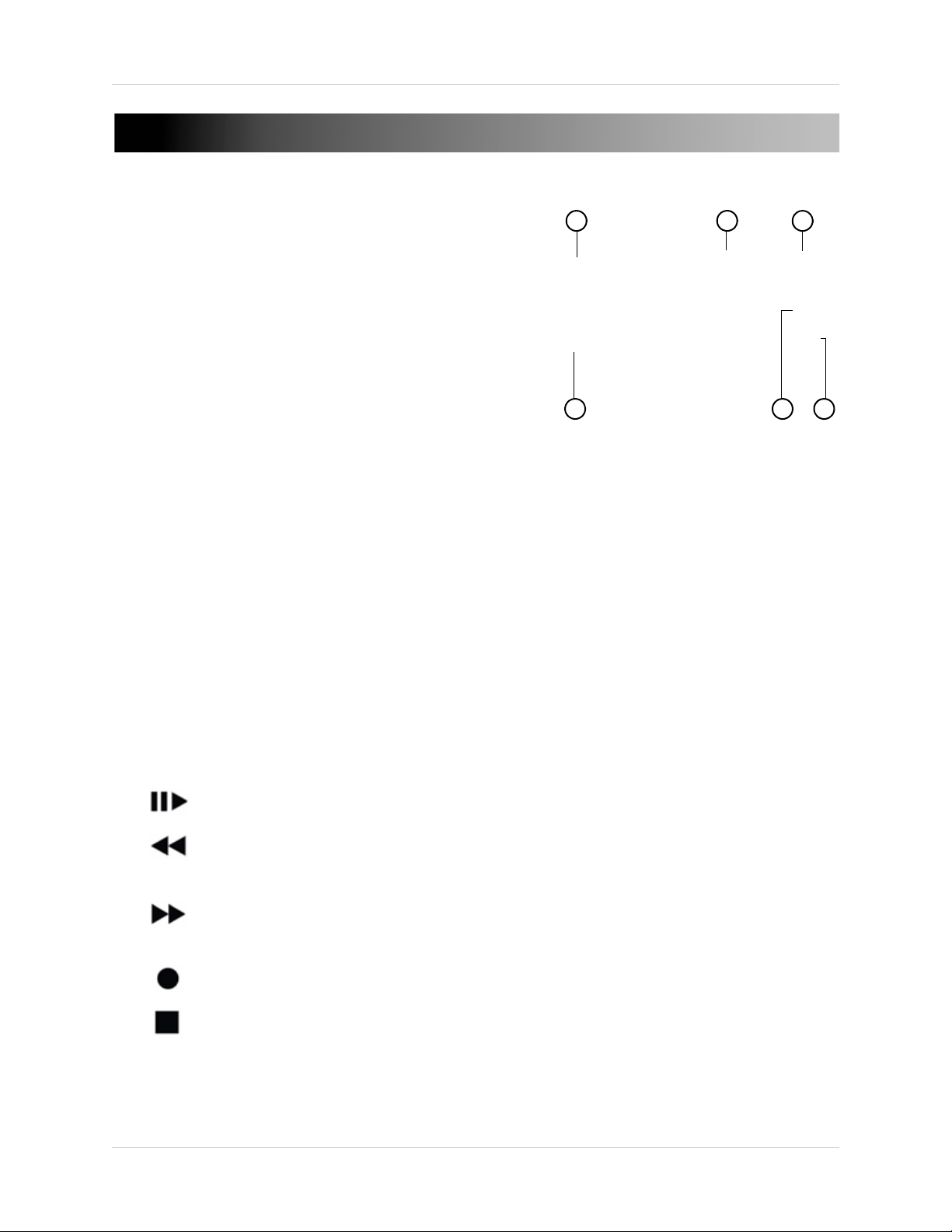
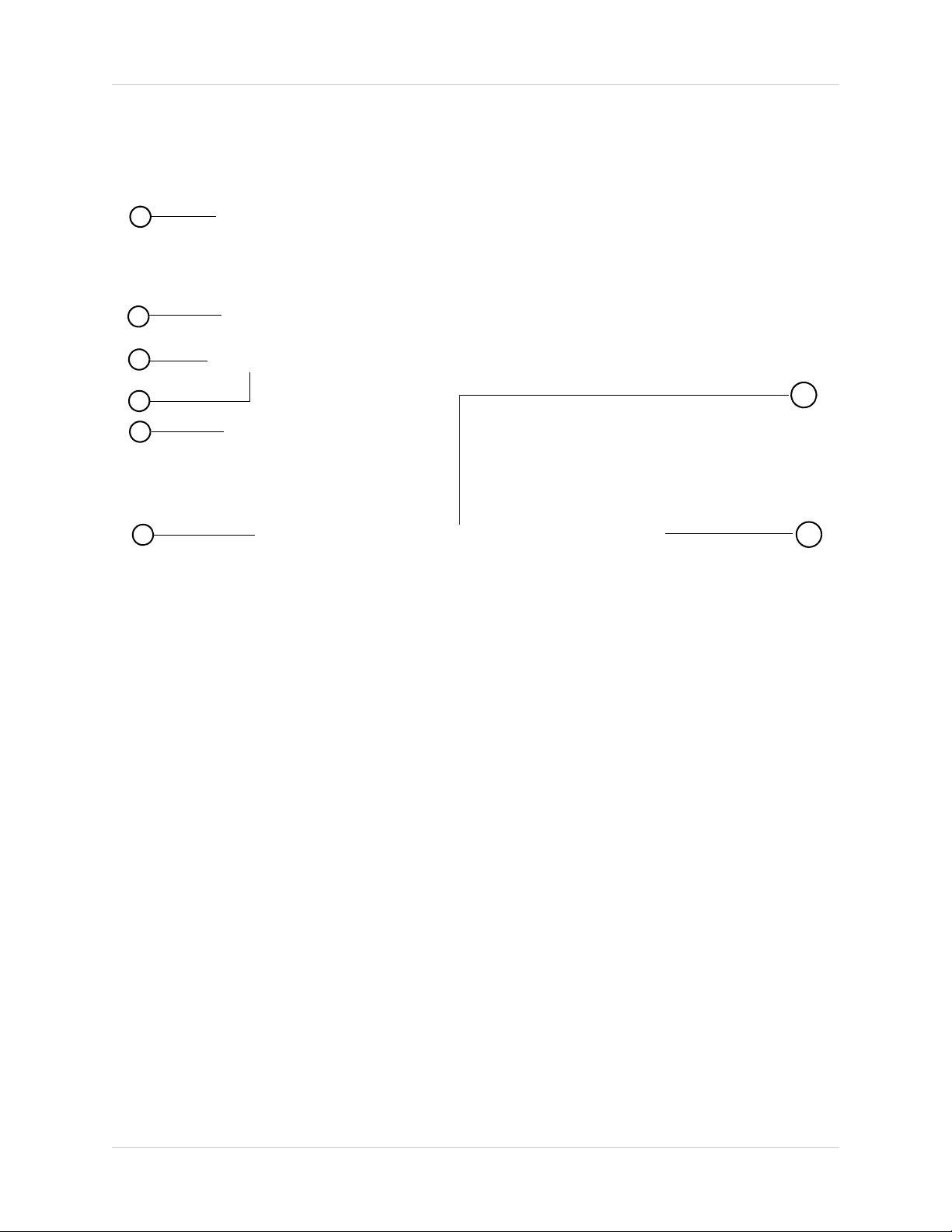
DH230: FRONT PANEL
1
2
3
4
65
1. Indicators:
• HDD: Flickers green to indicate hard drive activity.
• REC: Glows red to indicate system is recording.
• Backup: Opens the backup menu.
• Search: Opens the time-search menu.
• Display: Change split-screen views.
• Cancel: Press to exit from menus. In the main viewing window, press to toggle the on-screen
display on/off (i.e system time, recording indicators).
• Enter: Press to confirm a selection within menus.
2. Navigati
• Use the direction cursors (
During Playback:
• : Pause (Still Mode) / Play the video.
• : Rewind video. During Still Mode, press the Rewind button to move images
frame-by-frame in reverse.
• : Fast forward video. During Still Mode, press the Fast forward button to move images
frame-by-frame forward.
• :
• : Stop playback.
on cursor:
) to navigate the system menus.
Start/Stop recording (password required for stoppage)
3
Page 16
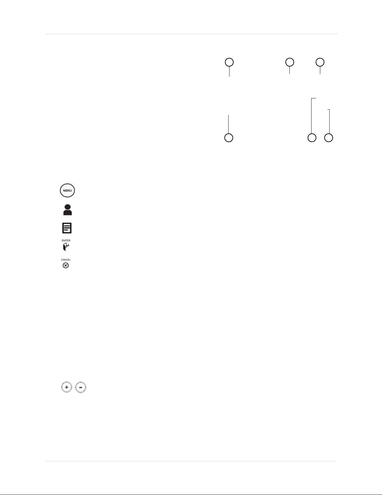
DH230: Front Panel
1
2
3
4
65
DH230: Front Panel (cont’d.)
During live view:
• : Press to open the Main Menu, and to confirm menu selections.
•
• : Press to display the system Log.
• : Press to confirm menu options/selections/ enter sub-menu options.
• : During Playback and menu navigations, press to exit the menu. In Live view, press to
•
3. POWER: Press to power the system ON/OFF (password required. Default password = 000000).
4. Channel n
• 1~1
• +10: Press the +10 button and a channel number to access channels 11 or greater. For example,
• : Increase/decrease values within system menus.
5. IR r
If your remote does not repond to the DVR, ensure the IR receiver is not blocked by objects.
6. USB P
connect a USB flash drive for firmware upgrades
: Press to open the Log-In window.
toggle the OSD on/off.
Press to toggle the Alarm window (appears on the top of the screen). The alarm window
displays any alarms that has triggered on the system.
umbers:
0/0: Use these buttons to enter numerical values within system menus, or to enter in the
user passwords. During Live view, press buttons 1~10/0 to view channels 1~10 in single channel
view. The 10/0 button has a numerical value of 0.
press +10 and 1 to access channel 11, press +10 and 5 to access channel 15 etc.
eceiver: IR receiver for the remote control. Keep the IR receiver clear from obstructions.
ort: Connect a USB flash drive, mouse, HDD, or optical drive for critical data backup;
4
Page 17
DH230: REAR PANEL
4
5
6
1 2
3
8 9 10
Rear panel (16-channel model shown)
7
1. CAMERA OUT (16 channel only):Port for octopus cable (16-channel models only). Connect up to 16 additional Loop Out monitors.
2. 75 Ohm (16-channel only): Controls the DVR’s impedance when using loop-out monitors. This prevents the colors connected to loop-out monitors from being "washed out".
3. CAM
4. DC 12V: Port for 12V DC 5A (4-channel) / DC 6A (8/16 channel) power supply (included).
5.
6.
7.
8. HDMI:
ERA IN: Camera input ports for BNC cameras
ALARM IN: Alarm block to connect external alarm or motion devices (not included).
•
RS422 : Connection block for an RS422 PTZ camera (not included).
LAN: Connect an Ethernet cable to connect the system to a router or switch (not included).
• USB port: connect a USB mouse, USB memory key, or external hard drive.
VGA: VGA port to connect the system to a VGA monitor.
HDMI port to connect the system to a HDMI TV/monitor.
NOTE: The HDMI port outputs to a maximum resolution of 1920 x 1080i. However, the recording
resolution is a maximum of 720x480 (D1 resolution). This means that when viewing pre-recorded
video, the image will not display in true HD form.
AUDIO IN (Top port): One 3.5" RCA port (mono) for recording audio from an audio capable
9.
camera (not included).
•
AUDIO OUT (Bottom port): One 3.5" RCA port (mono) for audio output.
10. VIDEO OUT (Top Port): Video output (BNC) to connect the system to a secondary monitor or DVR.
• SPOT OUT: Video output to connect the system to an external monitor (not included). Spot Out mode
displays channels switching in an automatic sequence.
5
Page 18
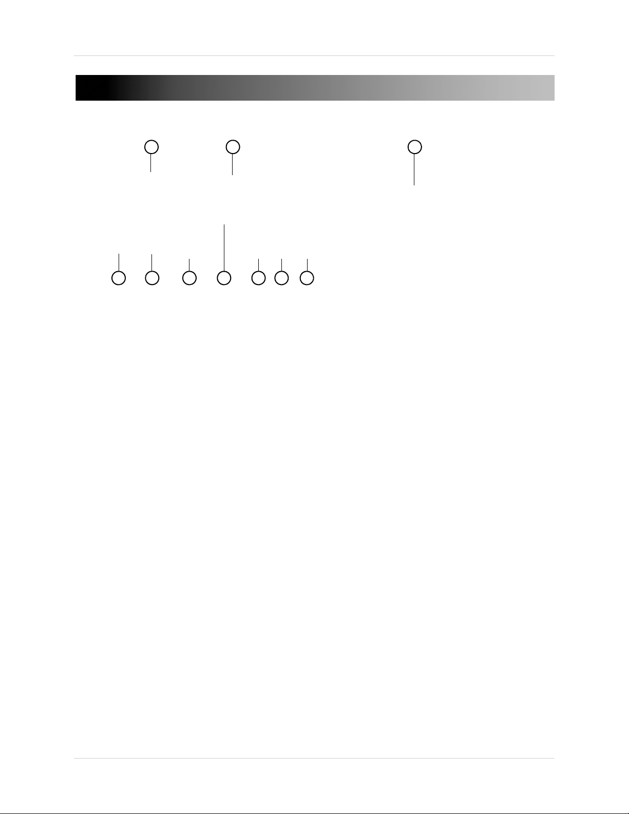
DH250: FRONT PANEL
4
5
6
1
2
3
7
1. Power Button: Press to power on/off the system (Password required).
2. Number Ke
when pressed during live view. Within menus, press the number keys to enter numbers. The
0/10 acts as "0" when pressed within menus.
3. Lock,
CK: Press to lock the system.
• LO
• BACKUP: Press to open the back up menu.
• EXT.SEARCH: Press to open the External Search menu. The External Search menu searches
for video on external storage devices (i.e. external USB hard drive).
• USB: Connect an external USB device (i.e. USB mouse or external USB hard drive).
4. DV
D-RW: Insert a blank CD-R / DVD-R media to back up video files.
5. Navigati
• :
• ENTER: Press to confirm a selection or save changes.
• CANCEL: Press to cancel a selection.
• MENU: Press to open the main menu.
• - / +: Press the - / + buttons to increase or decrease values within menus.
6. Play
back & Display buttons:
• STOP: Press to stop all recording (password required).
• REC: Press to resume recording after the system stops recording.
• PLAY: During playback, press to begin playback.
• STILL: Press to pause video.
• DISPLAY: Press to change split-screen views.
• ZOOM: During live view, press to open the zoom menu.
• P/T/Z FOCUS: In single-channel view, press to open the PTZ menu.
ys: Press to view channel in full screen mode. The 0/10 button acts as channel 10
Backup, and Search:
on buttons:
Press to navigate the system menu.
6
Page 19
• LOG IN / LOG OUT: Press to log in / log out of the system (password required)
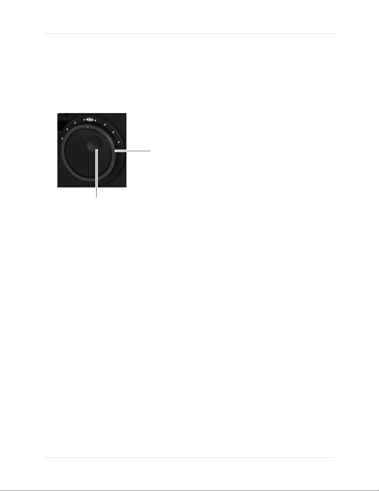
Shuttle
Wheel
Jog Ring
Using the Shuttle Wheel
During playback, twist the shuttle wheel
clockwise to increase the playback speed.
The further you turn the shuttle wheel, the
faster the system fast forwards. Release
the shuttle wheel to pause playback.The
same applies when twisting the shuttle
wheel counter-clockwise, except the video
plays backwards (reverse playback).
Using the Jog Ring
The Jog Ring allows you to play video
frame-by-frame (advance frame) during
playback.
To use the Jog Ring, pause the video, then
turn the shuttle wheel forward or backward
to play video frame-by-frame.
• TIME SEARCH: Opens the time search menu.
• LOG: Opens the system log menu.
• SHUTTLE HOLD: During the fast forward , or reverse playback mode using the Jog Ring/
Shuttle wheel, press the SHUTTLE HOLD button to lock the playback speed.
7. Jog Ring / Shuttle Wheel: Use the Jog Ring/ Shuttle Wheel to fastforward or rewind video during playback.
7
Page 20

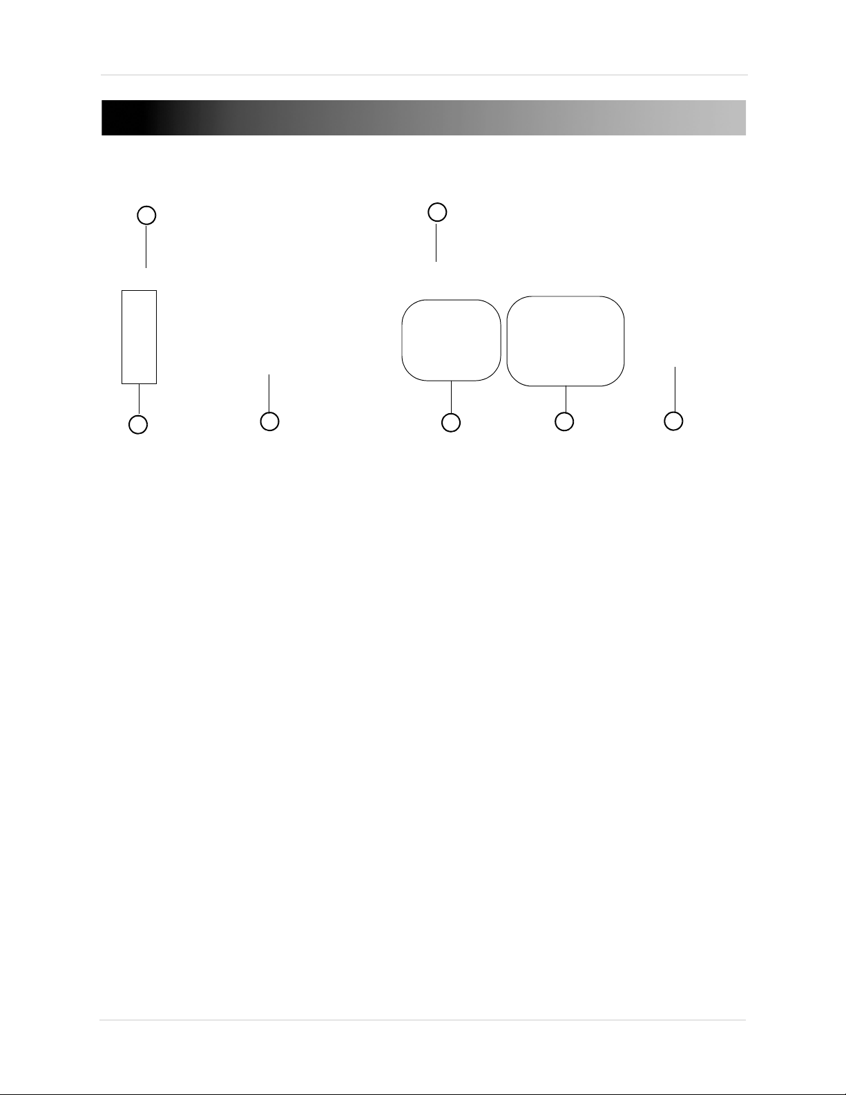
DH250: REAR PANEL
4
5
6
1
2
3
8 9
10
7
11
12 13 14 15 16
1. CAMERA IN: Camera input ports for BNC cameras.
2. CAM
3. AC
4. 75
5. AUDI
6. AUDI
7. VIDEO OUT: Video
8. SPO
9. VGA
10. HDMI: HDMI po
ERA OUT: Connect up to 16 additional Loop Out monitors.
IN: Connect a power cable to the AC IN port. Connect the other end of the cable to a power
outlet.
OHMS: Controls the DVR’s impedance when using loop-out monitors. This prevents the
colors connected to loop-out monitors from being "washed out".
O IN: Connect an audio-in octopus cable (9-pin to RCA) to connect up to 16
audio-enabled cameras or powered mic (not included).
O OUT: Connect one 3.5" RCA port (mono) for audio output.
output (BNC) to connect the system to a secondary monitor or DVR.
T OUT: Video output to connect the system to up to 3 external monitors (not included).
Spot Out mode displays channels switching in an automatic sequence.
OUT: VGA port to connect the system to a VGA monitor.
rt to connect the system to a HDMI TV/monitor.
NOTE: The HDMI port outputs to a maximum resolution of 1920 x 1080i. However, the recording
resolution is a maximum of 720x480 (D1 resolution). This means that when viewing pre-recorded
video, the image will not display in true HD form.
11. eSA
TA: Connect up to two eSata external hard drives for data backup.
12. USB: Connect an e
13. LAN1 &
LAN2: Connect an ethernet cable to connect the system to a router or switch (not
xternal USB device (i.e. USB mouse or external USB hard drive).
included). Connect an ethernet cable to either LAN1 or LAN2.
14. RS23
15. ALARM IN / RELA
16. Exhaus
8
2C: Not in use.
Y : Connect alarm sensors/ PTZ cameras to the ALARM IN / RELAY block.
t Fan: Keep the exhaust vent clear at all times.
Page 21
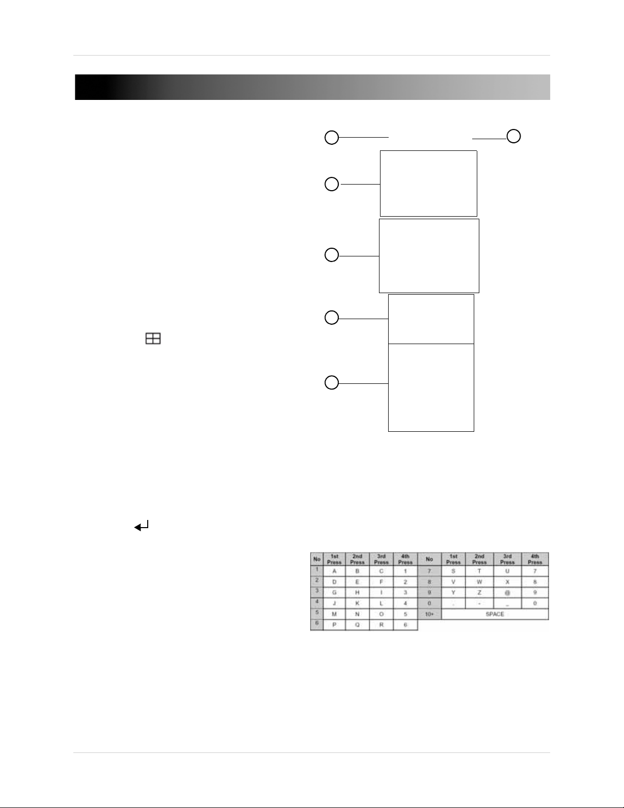
Remote Control
3
2
4
5
You can use the channel buttons on the remote
control to enter numbers, letters, and other
characters.
1
6
REMOTE CONTROL
1. DVR ID: Pairs the DVR with the remote (optional). For details, see “GENERAL” on page 54.
2. POWER: Press to power the system ON/OFF (password required).
3. S
ystem configuration buttons:
• TIME SEARCH: Press to open the Time Search
menu.
• EXTERNAL-SEARCH: Press to open the External
Search menu. The External Search menu allows you
to browse for content on an external hard drive
connected to the DVR.
•
LOG: Press to open the system log.
SPOT OUT: Press to select SPOT OUT output.
•
INFO: Press to view vital system information.
•
BACKUP: Press to open the Backup Menu.
•
DISPLAY ( ):Press to switch between single
•
channel full-screen, quad, and split-screen
di
splays.
• ZOOM: Press to open the zoom field (live view,
single channel only). Press ENTER to zoom in.
• P/T/Z: Press to open the PTZ menu.
4. Navigatio
S: Press to move cursor up
•
• T: Press to move cursor down
• W: Press to move cursor left
• X: Press to move cursor right
• ME
menu selections.
• ENTER ( ): Press to confirm menu options/
selections/ enter sub-menu options.
• CANCEL/OSD: Press to close menu windows; press
to show/hide the on-screen display (OSD); press to
clear channel indicators (loss, alarm, etc.).
• + / - :
n/Menu:
NU: Press to open the Main Menu, and to confirm
Press to increase/decrease menu options.
9
Page 22
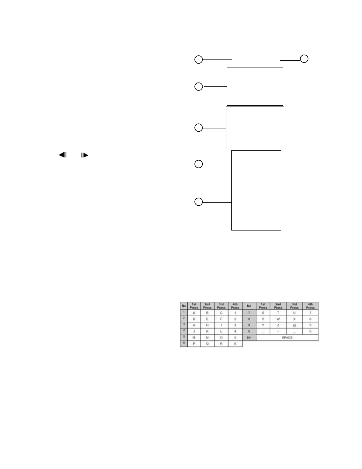
Remote Control
You can use the channel buttons on the remote
control to enter numbers, letters, and other
characters.
3
2
4
5
1
6
5. Playback controls:
: Press to stop playback
•
: Press repeatedly to increase reverse playback
•
speed
• WX: Press to begin playback; press to switch
between forward and reverse playback
• : Press repeatedly to increase forward playback
speed
•
z: Press to start/stop manual recording.
•
SCH/LOGIN: Opens the Login window to log in or
out of the system.
• and During playback, press to pause;
press repeatedly for frame-by-frame playback
6. Channel buttons: Press to view channels 1~16
individually in full-screen; press to input
passwords; when entering camera titles, press
for alpha-numeric characters. Note that the 0/
10 button means "0" when entering
passwords, and "10" when accessing channel
10 (16-channel models only).
10
Page 23
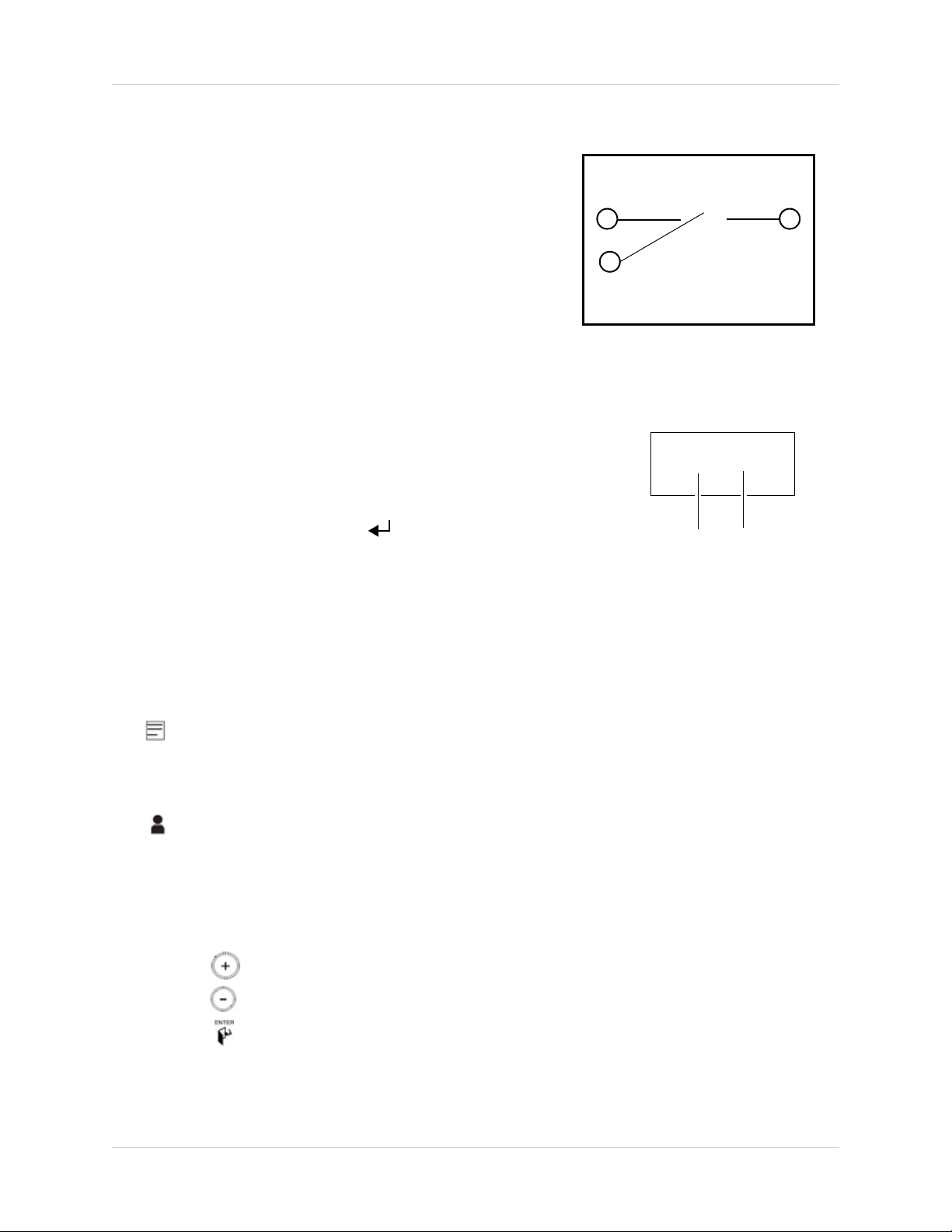
Mouse Control
1 2
3
Enter
Exit
The mouse is the primary control device for the system. To
connect a USB mouse:
• Connect a USB mouse to the USB port on the front or rear panel.
1. Left-Button: While in a split-screen display mode,
double-click an individual channel to view it in full-screen;
double-click again to return to the split-screen display mode.
While navigating menus, click to select a menu option;
double-click to open the next menu.
2. Right
3. Scr
-Button: Right-click anywhere on the screen to open the
Virtual Remote; double-click anywhere on the screen to
return to the previous menu.
oll-Wheel: Move the scroll wheel up or down to increase/decrease the value of a selected menu
option.
Mouse Tips
When using the mouse, the ENTER and EXIT buttons appear in the
top-right corner of every menu window. When you change system
Remote Control
settings and configurations, click (ENTER) to
save your
changes.
Touch Panel Tips and Tricks (DH230 only)
If using the Touch panel, you will often use the following
buttons when controlling the system:
• :
• /:
• /:
• /:
• Press the MENU button to open the main menu AND close
• Press the button to increase values for selected menu options
Menus
: move cursor up;
: show/hide OSD/ Alarm OSD;
viewing
Menus
: move cursor down;
viewing
: open Log menu
Menus
: move cursor left;
playback speed;
Menus
playback speed;
windows/exit. Press the MENU button to confirm menu selections.
NOTE: This manual refers to the CANCEL/ESC button on the remote control for closing/exiting menu windows. If
using the front panel, press MENU/ESC to close/exit menu windows.
Live viewing
: move cursor right;
Live viewing
Playback
: start/stop recording
: open the log in window.
: pause playback;
Playback
Playback
Playback
: stop playback;
: increase reverse
: increase forward
Live
Live
• Press the button to decrease values for selected menu options
• Press the button to confirm a selection.
11
Page 24

Using the System
The default system password is 000000
System
Password Field
USING THE SYSTEM
To power the system ON:
1. Connect the power cable to the port on the rear panel.
2. Press the
To power the system OFF:
1. Press the Stop button (
2. Enter your system password.
3. Press the PO
4. Enter your system password to shut down the system.
POWER button on the front panel or remote control.
)to halt system recording.
WER button on the front panel or remote control.
Password
The default system password is 000000. You can configure the system password through the Main
Menu>System>
users on the system, see “ACCOUNT” on page 54.
ACCOUNTS. For complete information on changing your password and managing
12
Page 25
On-Screen Display
1
2
7
8
3
4
5
6
The system shows the following for all display views:
Using the System
1. Recording Indicator: "REC" indicates that continuous recording is enabled on at least one channel.
NOTE:
2. Display: Show live video and playback in single channel full-screen, quad, and split-screen configurations.
If REC does not appear on the onscreen display the system is NOT RECORDING.
3. Recording Status & Channel indicator ( ): The number indicates the channel number. The colors have different meanings:
• Black - No recording in progress.
•
Yellow - Continuous recording in progress.
• Red - Event (Motion/Alarm) Recording in progress.
Channel Title: You can customize the channel with a unique name for each channel. See
4.
“CAMERA” on page 38.
5. Camera Status ( ): Will display a green Motion icon, purple Loss icon, or a yellow Alarm icon.
13
Page 26

Using the System
CD/DVD Drive Indicator
USB Indicator
(Front panel)
USB Indicator
(Rear panel)
User Status
Audio Indicator
Connected Users
6. Status Indicators
• CD/DVD Drive Indicator: Indicates that a CD/DVD writer is connected to the DVR. The indicator
glows blue when CD/DVD burning is in progress.
• USB Indicator (Front panel): Glows blue when a USB device is connected the front USB port
to perform a system backup.
• USB Indicator (Rear panel): Glows blue when a USB device is connected the rear USB port to
perform a system backup.
• User Status: Indicates what type of user is currently logged in.
• : The system administrator is logged in.
• : A user is logged in.
• : The system is locked.
• Audio Indicator: During video playback, if there is audio present, the Audio Indicator glows blue.
• Connected Users: Shows the number of users who are connected to the system via the network
(i.e through the web browser or smartphone).
7. Date/Time: Shows the date (mm/dd/yyyy), day of the week, and time (24-hour clock).
8. HDD/Rec
hard drive is full. Note that if the hard drive capacity is less than 5GB, the icon appears to
indicate overwrite is enabled. When overwrite is enabled, the first video that is recorded will be deleted
(f
irst in first out).
ord days: Shows the remaining hard drive space and the number of recording days before the
9. Spot Monitor Indicator: Displays the monitor that is currently in Spot Out mode.
14
Page 27
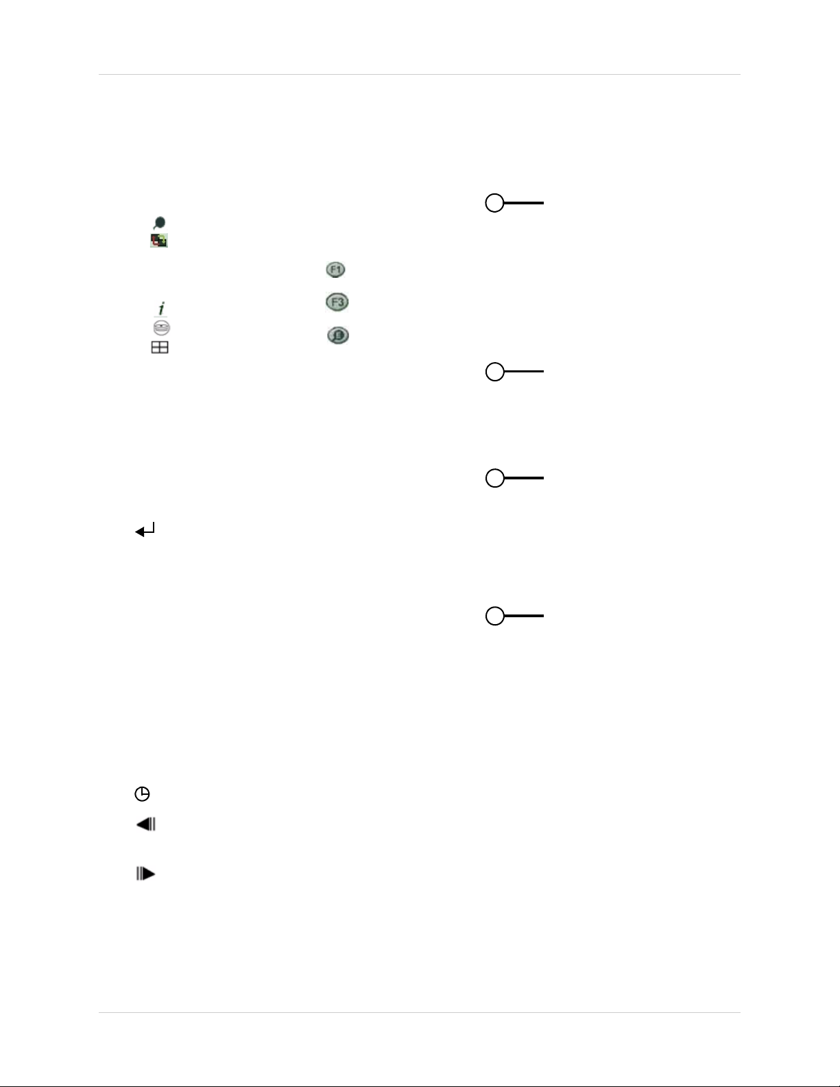
Using the Virtual Remote
2
3
1
4
• : Time Search
•
:Window
Positioning
• Log
• Spot Out
• System Info
• Backup
• : Display Mode
• Zoom
• PTZ: Opens the PTZ
menu.
• :F1 button.
• : F3 button.
• :External
Search
Right-click anywhere on the screen to open the Virtual Remote. The
Virtual Remote gives you quick access to many of the system’s
features using only a USB mouse (included)
1.
Quick Function Keys:
2. Navigation/Menu:
S: Move cursor up
•
• T: Move cursor down
• W: Move cursor left
• X: Move cursor right
NU: Press to open the Main Menu, and to confirm menu
• ME
selections.
.
Using the System
•
: Press to confirm menu options/selections/ enter
sub-menu options.
•
ESC: Close menu windows; press to show/hide the onscreen
display (OSD); press to clear channel indicators (loss, alarm, etc.)
• +: Increase values in menu options.
- : Decrease menu options in menu options
•
3. Playback controls:
: Stop playback / stop system recording
•
: Increase reverse playback speed 1X, 2X, 4X, 8X, and 16X
•
Start playback; press to switch between forward and reverse playback
• X:
: Increase forward playback speed 1X, 2X, 4X, 8X, and 16X
•
•
z: Start manual recording (if scheduled recording is not active)
• : Log in/ Log out of the system (password required)
• : During playback, click to pause; click repeatedly for frame-by-frame playback; during live viewing, click
to open the PTZ menu
• : During playback, click to pause; click repeatedly for frame-by-frame playback; during live viewing, click
to SPOT OUT
4. Channel butt
camera titles, click for alpha-numeric characters.
NOTE: The button labeled 0/10 means 0 when entering passwords, and 10 when entering channel 10 for the 16
channel model DVR.
ons: Click to view channels 1~8 individually in full-screen; click to input passwords; when entering
15
Page 28

Using the System
2
3
1
Virtual Remote during Playback
Playback
During playback, you can right-click anywhere on the
screen to open a condensed version of the Virtual Remote.
1.
Navigation/Menu:
• S: Move cursor up
• T: Move cursor down
• W: Move cursor left
• X: Move cursor right
NU: Opens system’s main menu.
• ME
•
: Click to confirm menu options/selections
• ESC: Click to close menu windows; clic k to show/hide the onscreen
display (OSD); click to clear channel indicators (loss, alarm, etc.)
• +: Increase values in menu options.
- : Decrease menu options in menu options
•
2. Playback controls:
: Stop playback
•
: Increase reverse playback speed 1X, 2X, 4X, 8X, and 16X
•
Start playback; press to switch between forward and reverse playback
• X:
: Increase forward playback speed 1X, 2X, 4X, 8X, and 16X
•
3. Quick Function Keys:
• : Click to open the Time Search menu
• Log: Click to open the Log menu
• : During playback, click to pause; click repeatedly for frame-by-frame playback
• : During playback, click to pause; click repeatedly for frame-by-frame playback
Using the Virtual Keyboard
When configuring certain options, such as Camera Title, the Virtual Keyboard opens to make
mouse input easier.
16
Page 29

Using the System
All recording must be stopped on
the system in order to set the time.
Date
Time
Setting the Time
It is highly recommended to set the time on the system prior to doing any recording.
To set the date and time:
1. Stop recording on the system by pressing
remote control and enter your 6-digit system password (by default, 000000).
NOTE: If using the mouse, right-click and then click on the Virtual Remote.
on the front panel, or press the button on the
2. Press the MENU
button to open the system menu. Select SYSTEM and press the ENTER
button. The System menu opens.
3. Select the TIM
4. Select DA
5. Select TIME and
NOTE: If using the mouse, use the Virtual Keyboard to enter the date and time.
6. Press the ENTER
7. Press the Canc
E tab.
TE and enter the date (yyyy/mm/dd).
enter the time (hh/mm/ss).
button to save your changes.
el button on the front panel, or press the ESC button on the virtual remote to
exit to the Live viewing window.
8. Press press the butt
on on the remote control to resume Continuous Recording.
NOTE: If using the mouse, right-click and then click on the Virtual Remote.
NOTE: Ensure the REC symbol appears on the top-left corner.If you do not see the REC symbol,
the DVR has stopped recording.
17
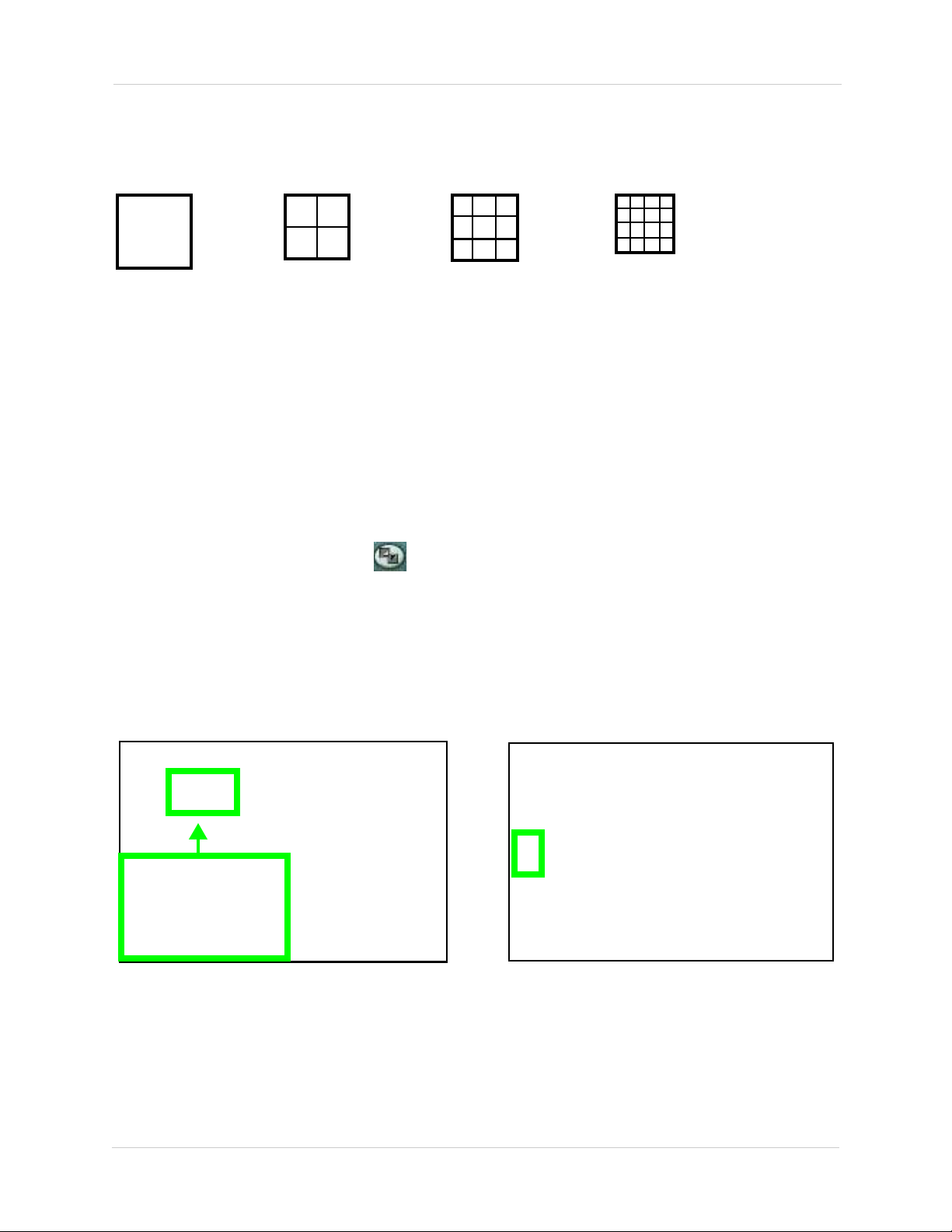
Page 30
Using the System
Full-Screen
Quad
Split-Screen 1
Split-Screen 2
(16-channel
models only)
Blue Window cursor is in channel 1
Press the 3 button to move channel 3 to the channel 1 position.
Channels repositioned
Channel 3 is now in the channel 1 position.
Multi-Screen Display
The system can display channels in full-screen single channel, quad, and multi split-screen
displays.
Repositioning Channels
You can reposition the channels on the display screen. This can be very useful when monitoring a
live location(s).
To reposition the display channels:
1. Using the mouse, remote control, or front panel,
quad display, or in a multi split-screen configuration.
NOTE: Repositioning will not work if the main display screen is in full-screen single channel.
place the main display screen in either a
2. Using the mouse, right-click anywhere on
3. From the Virtual Remote, click
. The Blue Window cursor appears in the top-left channel
the screen to open the Virtual Remote.
(typically channel 1).
4. Reposition the channels through the following:
• Remote Control: Press the button for the channel you wish to place in the location of the Blue
Window cursor. For example, if the cursor is on channel 1, and you want to have channel 4 in
its location, press the 4 button on the remote control. You can also press F2 on the remote to
open the Blue Window cursor, then press the desired channel number that you wish to change to.
nt Panel: Press the button for the channel you wish to place in the location of the Blue
• Fro
Window cursor
5. Press the STWX to change the location of the Blue Window cursor.
6. Press the
18
ENTER button to save your settings.
Page 31

RECORDING
Continuous recording on all channels (4CH model shown)
• In this example,
Continuous
Recording is on
ALL channels
(default)
REC icon
By default, the system is set to immediately record at startup from connected cameras. This is
called continuous recording. It is highly recommended to keep continuous recording on at all
times.
The system can perform Continuous Recording, E
However, the system can only perform one type of recording at a given time.
vent Recording, and Schedule Recording.
Continuous Recording
By default, all camera channels are enabled with continuous recording. During Continuous
Recording, the REC icon appears in the top left corner of the OSD.
Event Recording
The system includes three modes of event recording:
• Mo
• Alarm: The system records when an alarm or sensor is triggered
• Video Loss: The system records when a camera is disconnected or suffers video loss. The
system employs a pre-record function to capture video seconds before the video loss occurred
You can customize the recording parameters (video quality, frames-per-second) of Event Recording in the
Record menu. See “RECORD” on page 39.
19
tion: The system only records when motion is detected by the affected camera
Page 32

Recording
Motion assigned to channels (16- channel model shown).
Black icon = No recording
Motion was detected on the DVR (16 CH model shown)
Green Icon = Motion recording
Motion
When motion is detected, the system will continue to record, but can apply unique recording
parameters for each camera that you can set in the EVENT and DAY EVENT MENU [Main Menu >
Record > DAY or NIGHT (EVENT) > DAY or NIGHT EVENT]. The camera enabled with Motion
Detection will have a RED icon number on the OSD.
NOTE: A black icon indicates that recording on a camera is disabled. For better security it is
highly recommended to keep continuous recording for all cameras on at all times. Use caution
when assigning motion detection to specific cameras.
When motion is detected by the camera, the motion icon will appear.
NOTE: Press the CANCEL/ESC button on the remote control, front panel, or Virtual Remote to
clear the motion icon.
Alarm
When an alarm is triggered, the system will continue to record, but can apply unique recording
parameters that you can set in the EVENT and DAY EVENT menu (Main Menu>Record>Day or
NIGHT EVENT). A red channel icon appears when an alarm event occurs on the channel.
NOTE: Press the CANCEL/ESC button on the remote control, front panel, or Virtual Remote to
clear the alarm icon.
Video Loss
If a camera is disconnected or is damaged, the video loss icon will appear for the affected channel.
The channel number will turn BLACK.Once video has been restored, press the CANCEL/ESC
button on the remote control, front panel, or Virtual Remote to clear the video loss icon.
20
Page 33

Recording
ATTENTION: Schedule Recording takes priority over all other recording modes.
Schedule Use
Schedule Recording
Schedule Recording can be set manually or at startup. Schedule Recording features customizable
recording parameters that you assign to each camera.
To access the Schedule Recording tab:
1. Press the MENU button on the front panel, or virtual remote (right-click > MENU).
2. Click RE
3. In the GENERAL tab, Under SCHEDULE USE, select ON.
CORD.
4. Click the DAY, DAY EVENT tabs to configure scheduled recording. For details on scheduled recording, see “RECORD” on page 39.
Recording Audio
The system can record one channel of audio. You must have an audio enabled camera or
self-powered microphone connected to the system in order to use this function. For details on
connected audio recording devices, see “Appendix J: Using Listen-in Audio” on
page 154.
21
Page 34

PLAYBACK
Playback display view
CAM1
Playback speed indicator
View recorded video on the system through playback mode.
To begin playback:
1. Select the number of channels you wish to playback (i.e singl
e channel, or quad view etc.)
2. Press the Play butt
system will play the last few minutes of the most recently recorded video.
3. Press the following buttons on the remote control to use playback functions:
•
• : Press to pause playback; press repeatedly for frame-by-frame reverse playback
• : Press to pause playback; press repeatedly for frame-by-frame forward playback
•
•
To return to Live viewing:
• Press
on ( WX ) on the remote control or press X on the Virtual Remote. The
WX: Press to switch between forward and reverse playback
: Press to increase reverse playback speed 1X, 2X, 3X, 4X, 5X
: Press to increase forward playback speed 1X, 2X, 3X, 4X, 5X
to stop playback and return to live viewing
22
Page 35

SEARCH
- button
Select the
date, hour, and
minute
Enter button
+ button
Video playback buttons
Search for recorded video data on the system using the Time Search menu.
To open the Time Search menu:
• Press the Search button (
) on the front panel or remote control ( ).
To search for recorded video with Multi-channel playback:
1. Beside the "Day" field, click on the date you wish t
o search for. Then scroll DOWN (or click +
on the virtual remote) on the mouse to select the Hour. Select the desired hour. Scroll DOWN
(or click + on the virtual remote) again to select the desired minute.
2. Click the Enter button on the remote to begin video playback.
• Right-click to open the playback virtual remote. Use the video c
slow down the video.
3. Press
to stop playback and return to live viewing.
ontrol buttons to speed up or
23
Page 36

Search
EVENT RECORD search
Quick Search
To perform a quick search:
1. Press and hold the Sear
Time Input menu appears.
2. Double-click the INPUT field, and use the virtual k
wish to search for.
ch Button ( ) on the front panel of the system for 2 seconds. The
eyboard to enter the date and time that you
Event Record Search
The Event Record Search option allows you to search for any events that occurred on the system.
To perform an Event Record Search:
1. Press the SEARCH bu
tton ( ) on the front panel or remote control ( ).
2. Under SEARCH MODE, click the +/- buttons and select EVENT RECORD (default).
3. Click EN
4. Double-click on the event in the calendar that you wish to view (events are highlighted in red).
24
TER to begin the search.
Page 37

Search
Figure 10.7 Time Search Chart - Preview mode
Enter button
Event Preview Search
The Event Preview search allows you to view searched results as a thumbnail preview. This works
in single-channel search only.
To perform a preview search:
1. Press the Search button (
) on the front panel or remote control ( ).
2. Beside the "Day" field, click on the date you wish to search for. Then scroll DOWN on the
mouse to select the Hour. Select the desired hour. Scroll DOWN again to select the desired
minute. You can also press the -/+ button on the virtual remote to select the hour and minute.
3. Right-click to open the virtual remote, and then click on the channel that y
ou wish to preview
search.
4. Select the preview image that you wish to watch. A box outlines the preview image to indicate
the sel
ection.
5. Right-click to open the virtual remote, and then
6. To exit, right-click to open the virtual remote, and then click the Stop button (
click the Enter button to begin viewing.
).
25
Page 38

Search
Event Select button
Motion Area
Select all
Select none
Custom select
Select channel
If you click on Custom
Select, double-cilck the
grid to enable the
selected area to search
for motion.
Selected grids turn blue.
Motion Area Search
The Motion Area Search allows you to search for video with a pre-defined criteria.
To begin Event Area Search:
1. Press the Search button (
) on the front panel or ( ) on the virtual remote.
2. Click on the date that you wish to search for. Right-click to open the Virtual Remote. Click the + button to select the hour. After you have selected the hour, click the + button again to select the desired minute you wish to search under.
3. Click the Ev
4. Double-click the Search Mode field, and click +/- to select MO
ent Select button.
TION AREA. Note that by
default, the entire motion area is selected by default.
5. In the Motion Area window, configure the area of
motion (see below).
6. Press the MENU
26
button to search for video with your particular settings.
the screen that you wish to search for
Page 39

Search
External Search
External search allows you to search for video footage stored on an external device such as an
external hard drive. Note that the DVR can only search for video that is from the same model DVR.
Prerequisites:
• A USB 2.0 hard drive with data backed up from the same model DVR
To perform an External Search:
1. Connect a external USB hard drive to the USB port on the front or rear panel of the system.
2. Right-click to open the virtual remote, and then click .
3. Enter your system password if required.
4. In the EXTERNAL SEARCH menu, click -/+ and
search.
5. Press the ENTER butt
6. The Time Search menu appears. Perform a search to search for videos on your external hard
driv
e.
on. The system scans the external hard drive.
select the external device that you wish to
Event Source Search
Event Source search allows you to search for video on channels that have an alarm, motion, or
video loss event.
To perform an Event Source search:
1. Press the Search button (
2. Click on the date that you wish to search for. Right-click to open the Virtual Remote. Click the + button to select the hour. After you have selected the hour, click the + button again to select the desired minute you wish to search under.
3. Click the Ev
4. Under SEARCH MODE, click -/+ and select EV
5. Under Event Status, configure the following:
• ALARM: Select the alarm input you wish to search (input 1~4)
TION: Select the channel that you wish to search for motion (channels 1~16)
• MO
• VLOSS: Select the channel that you wish to search for Video Loss (channels 1~16)
6. Press MENU t
ent Select button.
o begin the search.
) on the front panel or ( ) on the virtual remote.
ENT SOURCE.
27
Page 40

Setting up Sequencing
Display
Switch
SETTING UP SEQUENCING
Sequencing allows you to view channels in a rotating interval. There are three modes of sequence
setup : sequence mode, shift mode, and event mode.
Sequence mode & Shift mode
Sequence mode allows you to display channels on a regular rotating interval. For example, the
monitor can display channels 1~4, then channels 5~8. Shift sequence mode retains the same split
screen view, but the channels change continuously within each channel cell.
To set up regular sequence mode:
1. Press the MENU
• If using a mouse, right-click to ope
2. Click DISPL
button on the remote or front panel to open the main menu. Press ENTER
n the virtual remote, then click MENU.
AY.
3. Click the SWIT
4. Beside DEVICE, select MAIN t
monitor. If you select SPOT, ensure a spot monitor is connected to the SPOT OUT port on the
rear panel.
5. Configure the following:
WELL TIME: Select the dwell time (the time duration before the channel changes).
• D
• MODE: Select SEQUENCE or SHIFT.
• SPLIT MODE (MAIN configuration only): Select the desired split-screen style.
• USE CHANNEL: Select the channels you want to view in sequence view.
6. Press MENU on the r
7. Exit to the main viewing window. Press and hold the DISPLA
remote or front panel to begin sequence view. Press DISPLAY on the remote, or the camera
number on the remote to exit sequence view.
CH tab.
o configure the main monitor or SPOT to configure the spot
emote or click ENTER.
Y button for 2 seconds on the
28
Page 41

Setting up Sequencing
Display
Switch
Ensure that the number
under MOTION matches
the channel number.
Event View
Event view allows the channel that detects an event (i.e. motion or alarm) to appear in the main
channel. This is especially useful if you set up sequence in single-channel view, but want to see
immediately any channels that detect motion.
To set up Event sequence mode:
1. Press the MENU button
• If using a mouse, right-click to open the virtual remote, then click MENU.
2. Click DISPLA
Y.
on the remote or front panel to open the main menu.
3. Click the SWIT
4. Beside DEVICE, select MAIN or
CH tab.
SPOT.
5. Configure the following:
• MODE: Sel
ect EVENT
• SPLIT MODE (MAIN configuration only): Select the desired split-screen style.
• USE CHANNEL: Select the channels you want to view.
6. Click the EV
ENT tab.
7. In the MOTION column, ensure the number matches the channel number as shown in the
image
above. For example, Channel 1 will have a Motion value of 1 etc..
8. Click ENTER.
29
Page 42

Setting up Sequencing
Camera 1
This tells camera 1 that if camera
5 detects motion, then camera 1
becomes the main channel.
Connect a monitor to the VIDEO OUT or SPOT OUT port (DH230) / CAMERA OUT port(DH250)
Connect the octopus cable
(16-channel only) to the CAMERA
OUT port , then connect loop out
monitors.
DH230
DH250
9. Exit to the main viewing window. Press and hold the DISPLAY button for 2 seconds on the remote or front panel to begin sequence view. Press EXIT on the front panel , or press the DISPLAY button on the remote to exit sequence view.
Configuring the EVENT tab
The EVENT tab allows you to set up cameras to trigger each other. For example, you can set up
Camera 1 (front door) to trigger Camera 5 (side door) to be the main channel when someone
approaches Camera 1 (front door).
Scenario: Camera 1 triggers camera 5 to be the main camera
1. Beside CH1, select camera 5 under MO
2. Click EN
TER to save your settings.
TION.
Connecting a SPOT OUT / CAMERA OUT monitor (DH230/250)
The SPOT OUT and VIDEO OUT ports allow you to connect addition monitors as outputs.
30
Page 43

Setting up Motion Recording
Click camera button
Motion detection area. Blue areas
indicate that the screen is enabled
for motion recording.
Record
DAY
SETTING UP MOTION RECORDING
Motion recording allows the system to mark events as motion recording. This allows you to search
for footage that only has movement.
Step 1: Configure Camera motion sensitivi
1. Press the MENU
button on the remote or front panel to open the main menu.
• If using a mouse, right-click to ope
2. Click CA
MERA.
ty & Configure Event frame rates
n the virtual remote, then click MENU.
3. Click the camera number button to select the camera you wish to configure.
4. Click the ( ) button to select the entire screen (selected by default) or click ( ) to
select certain portions of the screen by double-clicking the portions of the scr
een you wish to
enable motion.
5. Beside MOTION LEVEL, press -/+ to adjust the motion sensitivity.
6. Click EN
7. Click RE
TER to save your settings.
CORD>DAY.
NOTE: You
can also click on RECORD> under SCHEDULED USE, select ON. Click the NIGHT tab
and follow the same instructions below.
31
Page 44

8. Under EVENT, enter the number of frames you want the camera to record in if it detects
IMPORTANT
It is critical that the
camera number under
MOTION is the same as the
channel number you are
configuring.
This ensures that when
there is motion to that
particular camera, that it
will trigger motion
recording.
SCHEDULE
motion, under F/S. Repeat for any other cameras that you wish to enable motion recording.
NOTE: If you want to disable continuous recording, under CONTINUOUS, under F/S, select OFF.
This causes the system to record only when the cameras detect motion.
9. Under QUALITY, enter the desired video quality when the camera detects motion.
10. Click EN
TER to save your settings.
Step 2: Configure Cameras that have motion Enabled
1. Click the DA
Y EVENT tab.
2. Ensure that under MOTION, the camera number matches the number in CH.
Step 3: Configure Schedule settings
1. Click SCHEDULE.
32
Page 45

Setting up Motion Recording
Double-click on the day to configure.
The green motion icon and red channel icon indicates that the channel is set up for motion recording.
2. Double-click the days that you wish to enable Motion recording.
3. Configure the following:
• MODE: Cl
ick the +/- buttons to change to apply DAY recording, or NO REC to disable recording.
If you configured DAY recording in Step 1, select DAY.
NOTE: You cannot configure NIGHT recording to have a beginning and end time. However, if
NIGHT recording is chosen, the NIGHT recording parameters still apply to the schedule.
• BEGIN: Ent
er the time you want the scheduled recording to start.
• END: Enter the time you want the scheduled recording to end.
4. Click EN
TER to save your settings.
Final Result
When the camera detects motion, the ( ) symbol appears, and the channel number turns red
( ). The channel number turns red to indicate alarm
events will appear as EVENT. If the channel number does not
recording. During video search, motion
turn red, then motion recording has
not been enabled. Double-check to see that you have enabled motion recording in Step 1.
33
Page 46

Setting up Motion Recording
Event Edit icon
Camera 1 must be selected
Example
Select cameras
2 and 3.
Triggering secondary cameras in Motion recording
You can configure secondary cameras to begin motion recording when surrounding cameras
detect motion. For example, if Camera 2 and 3 detects motion, the system can trigger Camera 1
to begin recording as an event.
To configure custom Motion re
cording settings:
1. Under the DAY EVENT or NIGHT EVENT tab, click ( ) beside the channel that you wish to configure.
2. Under MOTION, ensure that whatever channel y
ou are configuring is selected. In this
example, Camera 1 must be is selected, since it is the camera you are configuring. Select
cameras 2 and 3.
3. Click EN
TER to save your settings.
Final Result
When camera 2 and 3 detects motion, camera1 begins recording as an event.
34
Page 47

Setting up Motion Recording
Event Edit icon
Select camera 1 and 2
Example
Triggering cameras to record during Video Loss
If video loss occurs, the system can trigger secondary cameras to begin recording as an event.
For example, if a vandal attempts to cut the camera wiring, as soon as the cable wire is cut, the
system triggers other cameras to detect as a motion event.
1. Under the DAY EVENT or NIGHT EVENT tab, click ( ) beside the channel that you wish to configure.
2. Under VLOSS, ensure that whatever channel you ar
Camera 1 is selected. Select cameras 2 and 3.
3. Click EN
TER to save your settings.
e configuring is selected. In this example,
Final Result
When video loss occurs on cameras 2 or 3, camera 1 begins recording as an eve
nt.
35
Page 48

Using the Main Menu
System Main Menu
1
2
3
4
5
6
7
8
USING THE MAIN MENU
To open the Main Menu:
• Press the MENU butt
on on the front panel or the remote control
1. DIS
2. CAM
3. RE
4. SCHEDULE:
5. DIS
6. NETW
7. DEV
8. SY
36
PLAY: Adjust OSD borders, split-screen configuration, and Auto Sequence settings.
ERA: Adjust brightness, camera titles, color, contrast, title, PTZ settings, and enable/
disable convert.
CORD: Enable/disable recording for each camera, configure the recording quality, frame
rate, and motion.
Customize DAY and NIGHT recording modes according to a daily or weekly
schedule.
K: Configure hard drive mirroring options, monitor hard drive status, and setting hard
drive modes (i.e. setting hard drive to master or slave)
ORK: Configure IP, email, and DDNS settings.
ICE: Configure post recording time, key sensitivity, audio recording, and alarm settings.
STEM: Configure video output settings, audio recording, alarm settings and PTZ event
settings.
Page 49

Using the Main Menu
Display Tab
DISPLAY
Use the Display menu to configure
the OSD and Auto Sequence
settings.
The Display menu categorizes in 3 sections --"GENERAL",
"SWITCH" and "EVENT".
2. Click ENTER to save your changes and exit.
SWITCH / EVENT
The SWITCH and EVENT tab allows you to
configure Sequencing display options for the
main and spot out monitor.
For details on setting up sequencing mode, see
“Setting up Sequencing” on page 28.
GENERAL
To configure the "GENERAL" display tab:
1. Select the GE
following:
• STATUS BAR: Select to Show or Hide the
status bar on the OSD.
MERA INFO: Select to show the CAMERA
• CA
NUMBER. or the CAMERA TITLE or both.
• BORDE
of the OSD.
CKGROUND: Set the background color for
• BA
disconnected cameras on the main display.
• OSD ALIGNMENT: Con
output to output to a VGA or CCTV monitor. If
you use a VGA monitor, select OVERSCAN. If
you use a CCTV monitor, select UNDERSCAN.
LIT MODE: Select the Split modes that you
• SP
want activated when you press the DISPLAY
button on the remote.
NERAL tab, and configure the
R LINE: Set the color for the borders
figure the DVR’s main
37
Page 50

Using the Main Menu
Camera number button
Select all
De-select all
Custom Select
If using "custom select", double click on the
grid to select the desired area that you wish to
activate motion.
CAMERA
Configure various camera settings,
such as brightness, contrast, title,
and covert.
To configure camera settings:
1. Click the camera number button to
c
onfigure the desired camera.
2. Configure the following:
• BRIGHTNESS, CONTRAST, COLOR: Adjust
from 0~100.
• MOTION LEVEL : Se
of the system. The greater the number, the
more sensitive the system is to motion. By
default, the motion level is set to 20.
• MOTION GRID:
that you wish to enable motion recording.
lect the motion sensitivity
Select the area of the screen
• PTZ : Click
PTZ settings. Enter your PTZ ID, Model, and
Baudrate. The PTZ ID should match the
camera channel to which you have connected
the PTZ camera.
NOTE:
the SETUP button to configure your
PTZ devices are connected to the
RS-422 ports located on the rear panel.
Multiple PTZ cameras are connected by
daisy-chaining the camera connection in
the RS-422 ports.
NOTE: For details on connecting PTZ
cameras, see “Appendix E: Connecting PTZ
Cameras” on page 133.
• TITLE: Enter the desired camera title.
3. Repeat for other camera connected to the system.
4. Click ENTER t
CANCEL/ESC to close remaining menu
o save your settings. Press
windows.
• TITLE: Use t
remote control to enter a name/title for the
camera. Press WX to move the cursor left/
right. If you make a mistake, press CANCEL/
ESC to return to the Main Menu and start
38
again.
he alpha-numeric buttons on the
Page 51

Using the Main Menu
MODE tab
Used FPS
Tot al FP S
RECORD
Configure recording parameters for
each channel.
GENERAL
To configure the GENERAL tab:
1. Click the GE
default).
2. Configure the following:
• SCHEDULE US
NIGHT and NIGHT EVENT tab. By default,
Schedule Use is turned off.
• BOOTUP RECORD: Turn this setting ON
(default) so that the DVR begins recording
automatically at system bootup. If this
setting is turned off, the DVR will not record
until you press the record button.
• DISK OVERWRITE: Turn this setting ON
(default) so that the hard drive
automatically erases the oldest data once
the hard drive is full (first in first out). If Disk
Overwrite is turned off, the system will stop
recording once the hard drive is full.
• AUTO DELETE: Configure the duration the
system should keep the data on the hard
drive before it is deleted. Select from 12
hours ~ 30 days. For example, if you choose
12 hours, the system keep the last 12 hours
of recording, deleting the older footage.
• PRE RECORD: Configure the amount of
time the system records before an event
recording. Select from 5 seconds ~ 300
seconds. For example, if an event occurred
at 12:00:00, and you have the pre-recording
NERAL tab (selected by
E: Select ON to configure the
time marked at 5 seconds, then during the
search, the video will begin at11:59:55.
3. Click ENTER t
• POST RECORD: Configur
time the system marks an event after an
event occurrs. Select from 5 seconds ~ 300
seconds.
o save your changes.
e the amount of
MODE
To configure the MODE tab:
Prerequisite: Stop the
before configuration. If the system is still
recording, you will not be able to edit the
settings in the MODE tab.
1. Click the MOD
2. Beside the camera number that you wish
o configure, set the following:
t
• Under RES. MAX F/S, se
and resolution the channel should record
in.
• As you adjust the frame rates, the frame
counter tells you how many frames you
have left to assign to remaining channels
(Used FPS).
• If you go over the total frame count, a
warning message appears. Click YES to
disable the last channel so that the
remaining channels can use the extra
frame rates.
3. Press /on the fr
button on the remote control to resume
Continuous Recording.
system recording
E tab.
lect the frame rate
ont panel, or press the
39
Page 52

Using the Main Menu
Event Edit icon
DAY
Configuring the DAY tab
The DAY tab allows you to configure how the
system will record during DAY re
Scheduled recording menu.
To configure the DAY tab:
1. Click the DA
2. Beside the desired channel you wish to
onfigure, adjust the following for
c
Continuous and Event recording:
• Under F/S,
of the particular channel during DAY
recording.
• Under QUALITY, select the recording
quality during daytime recording.
3. Click EN
Y tab.
select the frames per second
TER to save your settings.
cording in the
To configure the DAY EVENT tab:
1. Click the DA
2. Configure the following for each channel:
• ALARM: Sel
the system to mark the video as an event
when an alarm input triggers for the
selected channel.
• MOTION: Select the camera that you want
to trigger the camera being configured to
record as an event.For example, if you are
configuring channel 2, and enter channel 8
in the MOTION column, this tells the system
that when a video loss occurs in channel 8,
it will also cause channel 2 to record, and
mark the recorded video as an event.
Y EVENT tab.
ect from 1~4 or ALL. This tells
DAY EVENT
Configuring the DAY EVENT tab
The Day Event tab allows you to configure how
the
system will record an event if an alarm
trigger, motion or video loss occurs when the
DVR is in "DAY" recording mode. This setting is
used in the SCHEDULE menu, where you can
assign the system to record in "DAY" mode.
40
• VLOSS: Set the camera that you want to
trigger the camera you are configuring to
record, when the camera detects video
loss. For example, if you are configuring
channel 1, and enter channel 8 in the VLOSS
column, this tells the system that when a
video loss occurs in channel 8, it will also
cause channel 1 to record, and mark the
recorded video as an event.
• By default, the VLOSS channels are paired
to each other (i.e Channel 1 has "1" under
VLOSS, Channel 2 has "2" under VLOSS
etc.)
• Indicates multiple devices are
configured (See Event Edit below).
Page 53

• (EVENT EDIT) : Click this icon to open
Select ON
GENERAL tab
the EVENT EDIT menu.
About the EVENT EDIT window
The EVENT EDIT window allows you to have
other cameras trigger
the camera you are
configuring, to record as an event. For
example, you can tell the system to have
camera 1 record, when there is video loss in
camera 3. Likewise, you can tell camera 1 to
record as an event when there is motion
detected in camera 5.
Using the Main Menu
NIGHT
Configuring the NIGHT tab
The NIGHT tab allows you to configure how the
system will
the Scheduled recording menu.
To configure the NIGHT tab:
1. In the RECORD menu, click the GENER
tab.
2. Beside SCHEDULE USE, select ON.
record during Night recording in
AL
To configure the EVENT EDIT window:
1. Configure the following:
• ALARM I
N: Select the Alarm In devices
that, when triggered, will cause the camera
you are configuring to record as an event.
• MOTION: Set the camera (i.e. Camera A)
that you want to trigger the system to
record when the camera (Camera A)
detects motion. For example, if you are
configuring channel 1, and enter channel 8
in the motion column, this tells the system
that when a motion event occurs in channel
8, it will cause channel 1 to record, and
mark the recorded video as an event.
VLOSS: Select the channels to monitor for
Video Loss. For example, by default, all of
the VLOSS settings are selected. This
means that if any of the cameras are
disconnected (i.e. if a vandal cuts a camera
wire), it will trigger an event recording on
the camera you are currently configuring.
3. Click the NIGHT tab
.
4. Beside the desired channel you wish to
c
onfigure, adjust the following for
Continuous and Event recording:
• Under F/
S, select the frames per second
of the particular channel during NIGHT
mode recording.
• Under QUALITY, select the recording
quality during NIGHT mode recording.
5. Click ENTER t
o save your settings.
41
Page 54

Using the Main Menu
Event Edit icon
NIGHT EVENT
Configuring the NIGHT EVENT tab
The NIGHT EVENT tab allows you to configure
how
the system will record during Night
EVENT recording in the scheduled recording
menu.
1. Configure the following:
• ALARM: S
the system to mark the video as an event
when an alarm input triggers for the
selected channel.
• MOTION: Select the camera that you want
to trigger the camera being configured to
record as an event.For example, if you are
configuring channel 2, and enter channel 8
in the MOTION column, this tells the system
that when a video loss occurs in channel 8,
it will also cause channel 2 to record, and
mark the recorded video as an event.
• VLOSS: Set the camera that you want to
trigger the camera you are configuring to
record, when the camera detects video
loss. For example, if you are configuring
channel 1, and enter channel 8 in the VLOSS
column, this tells the system that when a
video loss occurs in channel 8, it will also
cause channel 1 to record, and mark the
recorded video as an event
• indicates multiple devices connected
(See "About the EVENT EDIT window")
elect from 1~4 or ALL. This tells
• (EVENT EDIT) : Click this ic
the EVENT EDIT menu
About the EVENT EDIT window
The EVENT EDIT window allows you to trigger
other cameras to record if an e
For example, if the camera outside your
garage (camera 5) detects movement, you can
trigger the camera inside the garage (camera
6) to begin recording as an event.
To configure the EVENT EDIT window:
1. Configure the following:
• ALARM IN: Sel
will triger an alarm recording.
• MOTION: Select the camera that will begin
recording when motion is detected.
For example, if you are configuring channel
1, and in the MOTION box, you select
channel 3, this means that when channel 1
detects movement, channel 3 will begin to
record as a motion event.
• VLOSS: Select the channels to monitor for
Video Loss. For example, by default, all of
the VLOSS settings are selected. This
means that if any of the cameras are
disconnected (i.e. if a vandal cuts a camera
wire), it will trigger an event recording on
the camera you are currently configuring.
2. Click ENTER t
ect the Alarm In devices that
o save your settings.
vent is detected.
on to open
42
Page 55

Using the Main Menu
Double-click on the day to configure.
SCHEDULE
Set a custom recording schedule
for the days of the week.
Pre-requisites:
• Ensure that you have configured the DAY
and
NIGHT recording settings in the
Recording menu. Select NO REC to disable
recording. For details, see “RECORD” on
page 39.
3. Configure the following:
• MODE:
appl, DAY, NIGHT orecording. Select NO
REC to disable recording.
NOTE: You cannot configure NIGHT
recording to have a beginning and end time.
However, if NIGHT recording is chosen, the
NIGHT recording parameters still apply to
the schedule.
• BEGIN: Ent
scheduled recording to start.
• END: Enter the time you want the
scheduled recording to end.
4. Click ENTER t
Click the +/- buttons to change to
er the time you want the
o save your settings.
CHART
To set a recording schedule in the CHART tab:
1. Click the CHART t
2. Double-click the day that you wish to
c
onfigure.
ab (default).
HOLIDAY
Configuring the Holiday schedule
The holiday schedule allows you to apply a
cus
tom recording schedule for a set duration.
This is useful if you will be away from the
system, and want to automate a specific
recording schedule.
Pre-requisites:
• Ensure that you have configured the DAY
and NIGHT r
Recording menu. For details, see
“RECORD” on page 39.
• Ensure that you have configured a
recording schedule in the CHART tab for
each date (Sunday - Saturday).
ecording settings in the
43
Page 56

Using the Main Menu
To configure the Holiday schedule:
1. Click the HOL
IDAY tab.
2. Configure the following:
• MODE:
Select the reco rding mode you wish
to apply. Choose from OFF, DAY, NIGHT,
SUNDAY~SATURDAY, or CUSTOM.
• MM/DD: Enter the month and date you want
the holiday recording to start.
• DAYS: Enter how many days you want the
holiday recording to last. For example, if
you select 2 days, holiday recording will be
enabled for 2 days, and then resume to the
regular recording mode (continuous).
NOTE: If a holiday schedule occurs on the
same day as a weekday schedule, the
holiday schdule overrides the weekday
schedule.
3. Click EN
TER to save your settings.
44
Page 57

Using the Main Menu
DISK
Use the Disk menu to format the
internal HDD, and configure
Overwrite, Disk Monitor and Disk mirroring
settings.
DISK MANAGER
Disk Manager Tab
• Damaged: The hard drive is unusable.
Formatting a new hard drive
You must format a new hard drive before it can
be
used for recording.
To format a new hard drive connected
system:
1. Install the new internal hard drive to the
R.
DV
2. Under DEVICE, select the hard drive. The
naming c
this : "INT-A: Unknown".
3. In the ACTION field, click +/- and
Assign to Record.
4. Click Start t
the formatting is complete, the hard drive
shows up in the RECORDING DISK tab.
Mirroring (RAID 1)
onvention looks something like
o format the hard drive. After
to the
select
The Disk manager tab allows you to view
connected hard drives/
configure hard drive mirroring, and hard drive
health.
CD/DVD writers,
Understanding the Status readings
The Status column indicates devices that are
connected to the system, and the health of the
hard drive.
Below is a list of titles that you may see under
the Status
• CD/D
the system.
• Unknown: A new hard drive is installed, but
not formatted.
• Empty: The hard drive has been formatted,
but not currently used in the system.
• Record Data: There is data on the hard
drive, but it is not currently used in the
system to record.
• Back up Data: The hard drive has back up
data stored.
• Other Data: The hard drive does not include
backup or recording data.
column:
VD: A CD/DVD drive is connected to
The mirroring feature allows two hard drives
to write duplicate data to onto eachother.
event that one hard drive fails, there will
always be a back up hard drive with identical
data.
To set up disk mirroring:
1. Ensure you have two internal hard drives
nstalled in the system.
i
2. Under DEVICE, select the two hard drives
ou wish to set up for disk mirroring.
y
3. In the ACTION field, click +/- and sel
Assign to R&M (R&M stands for Record
and Mirroring).
NOTE: The two hard drives should be
identical in brand/model/capacity. If one
hard drive is smaller, the system will
recognize the smaller hard drive as the
maximum storage capacity.
4. Click Start t
the formatting is complete, the hard drives
will be set up in mirror mode.
o format the hard drive. After
In the
ect
45
Page 58

Using the Main Menu
Record + Mirror
The Record+Mirror function allows you turn a
hard drive
that is assigned as a recording hard
drive, into a mirroring hard drive.
1. Ensure you have two internal hard drives
talled in the system.
ins
2. Under DEVICE, select the hard drive you
to set up for disk mirroring.
wish
3. In the ACTION field, click +/- and sel
ect
MIRROR ON INT-A.
NOTE: The two hard drives should be
identical brand/model/capacity.
4. Click Start t
o format the hard drive. After
the formatting is complete, one hard drive
will be set up for mirroring, and the other
for recording.
Initializing (formatting) a hard drive for
backup
Before the system can detect an internal hard
drive, it must be ini
tialized.
3. In the ACTION field, click +/- and sel
ect
Link Record Disk.
4. Click Start t
o begin the process.
Limitations of the Record Disk function:
• You must remove the original hard drive
bef
ore installing the new hard drive from
another system.
• The hard drive must be from the same DVR
series.
Recording Disk
The Recording Disk tab lists the drives that are
currently used for system recording.
To initialize a hard drive:
1. Connect the internal hard drive to the
stem.
sy
2. Under DEVICE, select the drive you wish to
lize.
initia
3. In the ACTION field, click +/- and sel
ect
Initialize for backup.
4. Click Start t
o begin formatting.
Link Record Disk
The Link Record Disk function allows you to
install
a hard drive from a different DH230
series DVR without formatting. This is useful if
you have several DH230s, and wish to swap
hard drives for viewing/backup purposes.
To use the Link Record Disk function:
1. Connect the internal/external hard drive to
the sys
tem.
2. Under DEVICE, select the drive you wish to
lize.
initia
The Recording Disk menu displays the
llowing:
fo
• SIZE, RANGE: Displays the har
d drive size,
and the duration of recording.
• DEVICE: Displays the type of device
connected to the system.
• STATUS: Displays the hard drive health
status.
• STABLE: The hard drive works
properly.
•
SYNC: The system is copying data from
the master to slave hard drive.
•
RE-SYNC:The system is forcing
pending buffered disk writes to the new
hard drive.
•
RECOVER: The system is forcing
pending buffered disk writes to the
slave drive.
•
FAULTY: Hard drive error.
• ACTION: Click the REMOVE button to
unmount a hard drive. Click YES when the
confirmation window appears to unmount
the hard drive from the system.
46
Page 59

Using the Main Menu
NETWORK
Configure network and DDNS
options.
ETHERNET
The ethernet tab displays the current system
IP, netmask, gateway and DNS server IP.
Configuring Network Type: STATIC vs DHCP
The system has the ability to operate in DHCP
mode an
router to assign an IP to the DVR. Static IP
mode fixes the IP of the DVR. Fixing an IP of the
DVR ensures that the IP will not change.
To change between Static IP and DHCP:
1. Beside CONFIG, select ST
2. Click EN
To manually configure IP settings:
1. Beside CONFIG, select ST
2. Configure the following:
3. Click EN
d Static IP mode. DHCP allows the
ATIC IP or DHCP.
TER to save your settings.
ATIC IP.
• IP ADDRESS
• NETMASK
ATEWAY
• G
• PRI. DNS SERVER
• SEC. DNS SERVER
TER to save your settings.
GENERAL
The general tab allows you to configure the
system port number, and various security
settings.
To configure the GENERAL tab:
1. Configure the following: CESS PORT: Enter the desired system
• AC
port number (default port 80).
• BANDWIDTH: Select from UNLIMITED,
4,8,16,32,64,128 ,256,512 KBPS; 1,2,4,8
MB.
• PING BLOCK: Select ON to prevent outside
connections from pinging the DVR.
• SCAN BLOCK: Select ON to prevent outside
connections from scanning the DVR.
• STREAM MODE: Select from DUAL or
OPTIMIZED. Select OPTIMIZED to allow the
DVR’s built-in algorithim to determine the
best video and audio streaming settings.
Select DUAL to configure your own
streaming quality under STREAM
PROPERTY.
• STREAM PROPERTY: Configure the frame
rate the video streams during remote
viewing. To configure the Stream Property,
Under STREAM MODE, select DUAL. Select
the video streaming quality (choose from
Low~Ultra). The higher the video quality,
the greater the bandwidth consumption.
2. Click ENTER t
o save your settings.
47
Page 60

Using the Main Menu
Event Edit icon
To configure the EVENT EDIT
(EMAIL) window:
1. Configure the following:
• ALARM IN: Select the alarm in
devices that will cause the
system to send email
notifications if an alarm is
triggered.
• MOTION: Select the channels
that will cause the system to send
email notifications if motion is
detected.
• SYSTEM: Select the events that
will cause the system to send out
email notifications. For a list of
icons and what they mean, see
the next page.
• Click ENTER to save your
settings.
EMAIL
The DVR can send out email notifications when
a motion or alarm event occurs.
To use the Digimerge email server
ecommended):
(r
1. Beside USE, select DEF
2. Configure the following:
• EV
ENT: Select how frequent you want the
system to send out email alerts. Note that
the system only sends out a email
notification if there is an event trigger (i.e.
motion or alarm trigger).
• Log : Select how long the system logs
should be (select from 1 day or 1 week).
• Retry Count: Enter the number of times
the system attempts to re-send the email
notification.
AULT.
• Log (Email Sour
checkbox if you want the system to email a
system log.
• Attach Picture: Select ON for the system
to attach an image in the email alerts.
• Email Address: Enter up to 5 email
addresses that will receive email
notifications from the system.
3. Click ENTER t
• Ev
ent Edit ( ): Click this icon to
configure the type of alarm settings that
will cause the system to send out email
alerts.
ce): Select the Log
o save your settings.
48
Page 61

Using the Main Menu
Select SMTP
What the SYSTEM icons mean:
1. HDD DISK FAIL: A hard drive error occurred.
2. RECORD SYSTEM FAIL: The system stopped recording.
3. TEMPERATURE WARNING: The system is overheating.
4. VOLTAGE WARNING: There was a surge in electrical output.
5. LOW RTC BATTERY WARNING: The system’s internal clock battery is low.
3. Configure the following:
• Serv
er: Enter the SMTP server name.
• Port: Enter the SMTP port number.
• Authentication: Select ON/OFF.
• User ID: Enter your SMTP user ID.
• Password: Enter your SMTP password.
• Send Test: Click the Start button to send
out a test email to your SMTP email
account.
4. Click ENTER t
o save your settings.
6. EXTERNAL DEVICE EVENT: A USB device has been removed.
7. NETWORK LINK DISCONNECT: The ethernet cable was unplugged.
To use a custom SMTP email server:
1. In the EMAIL tab, select SMTP.
2. Click the SMTP ta
b.
49
Page 62

Using the Main Menu
Connecting to your system
After you have port forwarded the required
port, created a DDNS account, and enabled
DDNS on your system, you must enter the
DDNS URL into Internet Explorer to access
your DVR.
The DDNS URL must include http:// , the
name of your DDNS URL, followed by a
colon, then the port number of your DVR.
For example:
http://tomsmith.digimerge.net:80
DDNS URL
Port Number
NOTE: If you change your default port
number (port 80) to a different port, you
still need to enter your port number after
the DDNS address.
Entering DDNS information using the
remote
• Press the + / - buttons to enter
alpha-numeric characters.
OR
• Press the number buttons on the
remote to enter letters and numbers.
• Press the arrow keys to move to the
next character.
DDNS
Configure Digimerge DDNS settings.
NOTE: You must register for the FREE
Digimerge DDNS service prior to
configuring DDNS settings.
To configure DDNS settings:
1. Under USE, select
2. Under DOMAIN NAME, enter only the firs
portion of your DDNS domain from the
confirmation email. For example, if your
domain name is tomsmith.digimerge.net,
you only need to enter
field.
3. Under USER ID, enter your
user name
4. Under PASSWORD, enter your
DDNS password
NOTE: Obtain your Digimerge DDNS user
name and password from the confirmation
email.
5. Under UPDATE TEST, click
successful, you will see "GOOD." If
unsuccessful, you will see "ERROR." If you
receive an error, please check your
network connections and carefully
re-enter your Digimerge DDNS
information.
6. Click EN
.
TER to save your settings.
DIGIMERGE.
tomsmith
.
t
in the text
Digimerge DDNS
Digimerge
START. If
50
Page 63

Using the Main Menu
DEVICE
Configure Alarm Out, Alarm Buzzer,
and alarm input settings.
GENERAL
The GENERAL tab allows you to configure Post
Recording time, Audio recording, Key Tone
(key "beeps"), and Key Sensitivity.
1. Configure the following in the General tab:
PLAY: Select the output resolution.
• DIS
• AUDIO RECORD: Select ON or OFF to
enable or disable audio recording.
• KEYPAD MODEL: Select the PTZ keyboard
model and baud rate.
• EXTENDED DEVICE: Select the desired
device
• PTZ EVENT: Select the duration of a PTZ
event.
• ALARM OUT: Select the duration of an
alarm out event.
2. Click EN
TER to save your settings.
ALARM
The ALARM tab allows you to configure the
system Alarm Buzzer and Alarm Input type on
each channel (i.e. N.O and N.C (normally open
and normally closed) settings)).
1. Configure the following in the Alarm tab:
• INPUT: Sel
the particular channel. Select from N.O or
N.C (Normally Open, or Normally Closed).
• OUTPUT: Select N.O (Normally Open) or
N.C (Normally Closed). Under INACTIVE,
select the event type (Manual or Event).
• BUZZER:Select ON/OFF. Under INACTIVE,
select the event type (Manual or Event).
• CONTROL: Turn the OUTPUT/ BUZZER on
or off. To enable the ON button , under
INACTIVE select MANUAL.
2. Click ENTER t
ect the alarm type connected to
o save your settings.
51
Page 64

Using the Main Menu
Edit Event icon
PTZ EVENT
3. Click the EDIT EVENT icon( ) beside
OUTPUT/BUZZER to configure the actions
follow when an alarm output occurs /
that
buzzer. The alarm output must be set to
N.C or N.O before you can access the Edit
Event window.
4. Configure the following in the EVENT EDIT
(ALARM OUT 1)
• ALARM I
N: Select the other alarms that
Window:
will also trigger when Alarm OUT 1/
BUZZER activates.
• MOTION: Select the cameras that will
cause ALARM OUT 1/BUZZER to activate
when motion is detected.
• VLOSS: Select the cameras that will cause
ALARM OUT1/BUZZER to activate when
video loss occurs in one of the cameras.
• SYSTEM: Select the events that will cause
ALARM OUT 1/BUZZER to activate.
The PTZ Event menu allows you to configure
the PTZ camera to go to a pre-defined pre-set
or tour setting when an event occurs. For
example, if camera 1 detects movement, the
PTZ camera (camera 2) will automatically pan
towards the front door.
To configure the PTZ Event tab:
1. Configure the following:
• CHANNEL: Sel
ect the channel number the
PTZ camera is connected to.
• ACTIVE: This setting instructs what action
the PTZ camera performs when an event
occurs. Select from NONE, GOTO or TOUR.
• In the number field, enter the GOTO or
TOUR preset number. This number is
programmed into the PTZ by the user.
• INACTIVE: This setting instructs what
action the PTZ camera performs after an
event has ended. Select from NONE, GOTO,
or TOUR.
• In the number field, enter the GOTO or
TOUR preset number. This number is
programmed into the PTZ by the user.
5. Click EN
CANCEL/ESC to close remaining menu
TER to save your settings. Press
windows.
52
Page 65

2. EDIT EVENT ( ): Click this icon to
TIP!
If an alarm is triggered on
the system, press the
Cancel/ESC button to
cancel the buzzer (if
enabled). Cancelling the
buzzer
will not
stop
recording.
open the PTZ EVENT EDIT window. This
ows you to configure the type of events
all
that will trigger the PTZ camera.
3. Configure the following:
• ALARM I
N: Select the alarms that triggers
the PTZ camera to move to a pre-defined
location when the Alarm Input triggers.
• MOTION: Select the cameras that triggers
the PTZ camera to move to a pre-defined
location when the cameras detect motion.
• VLOSS: Select the cameras that cause the
PTZ camera to move to a pre-defined
location when Video Loss occurs on the
selected cameras.
4. Click EN
TER to save your settings.
Using the Main Menu
Alarm recording will take priority over
con
tinuous recording, even if a camera is
disabled in standard recording parameters.
53
Page 66

Using the Main Menu
SYSTEM
Configure System settings.
GENERAL
To configure general system settings:
1. Configure the following:
• CONTR
a DVR with a remote. For example, if you
have several DVRs in the same room, and
you want to control them with one remote,
you can pair the remote to the DVR, so that
the remote will only control that particular
DVR.
To pair a remote to the DVR, enter a number
from 00~99. Click ENTER to save your
settings.
On your remote control, press and hold the
DVR ID button while pressing the number
of the CONTROL ID. The Control ID number
and the number you enter into your remote
control must be the same.
• DVR NAME: Enter the desired DVR name.
This name will appear when you connect to
the DVR remotely.
• KEY TONE: Select ON/OFF to enable or
disable the ’beep’ when you press the
buttons on the front panel.
• PB DEINTERLACE: Turn this setting ON to
reduce image flickering, with lowered
picture quality. Turn this setting OFF to
have better picture quality, but with some
image flickering.
• AUTO LOGOUT: Turn ON/OFF to enable or
disable users from being automatically
OL ID: This setting allows you to pair
logged off of the system. Enter the desired
time before a system logs a user off.
• SMART MONITOR: Turn ON/OFF to show
or hide the hard drive S.M.A.R.T status in
the DISK menu.
• KEY SENSITIVITY: Press -/+ to increase or
decrease the button sensitivity on the front
panel of the system.
TIME
For more details, on setting the date and time,
see “Setting the Time” on page 17.
ACCOUNT
Only the ADMIN can configure user
authorities on the system.
To configure user and account settings:
1. Select the ACCOUNT tab, and configure
ollowing:
the f
USER/NAME: Click the -/+ button to
•
configure the user type. You can change the
default admin login name. Configure up to
5 users.
• ACTIVATE: Select ON/OFF to enable or
disable Users 1~5.
• PRIVILEGE: Select the type of menus that
the user can control.
• NETWORK: Enter the network password
for the particular user, or deny users
entirely from connecting remotely. Select
from DENY, CUSTOM P/W, or SYSTEM P/W.
• PASSWORD: Enter your new user or admin
password.
2. Click
ENTER to save your settings.
54
Page 67

Using the Main Menu
UPDATE
Use the Update menu to upgrade system
firmware.
NOTE: The system supports most major
brands of USB flash drives with a capacity
of 10 MB ~ 16 GB.
To upgrade firmware:
1. Download the latest firmware update from
the Digimer
2. Copy the firmware to a blank USB flash
e.
driv
NOTE: Do not have any folders on the USB
flash drive—just the firmware file.
3. Connect the USB flash drive to the USB
on the front or back panel.
port
4. Stop all recording on the system.
NOTE: You must stop all recording in order
to perform the upgrade.
5. Open the Main Menu and select
6. Under the UPDATE tab, select
7. Select
Firmware upgrade begins.
the USB flash drive until the upgrade
process is complete.
buttons or power off the system during the
upgrade process.
When upgrade is finished, click the REBOOT button
in the prompt window to restart the system.
ge website.
SYSTEM.
UPDATE.
START and press the ENTER button.
Do not
Do not
remove
press any
INFO
View important system information:
• S/W VERSION: The curr
firmware version.
• DOMAIN NAME: Your Digimerge DDNS
domain name.
• MAC: The physical address of the DVR on
your network.
• LANGUAGE: The current system language.
• NETWORK: The IP address of the system
• RECORD DISK: HDD, size and space
remaining.
• DISK SUMMARY: The status of the HDDs,
and what state they are in.
• STREAM: the hard drive is in recording
mode
• 0 MIRROR: the hard drive is in RAID
mo
de
• SYSTEM HEALTH: Indicates system
temperature and voltage.
• DISK ORDER: Displays the internal system
disk order.
• EXTERNAL 1 & EXTERNAL 2: Displays
devices connected to the USB port.
• USB (FRONT): The status of the USB port
on the front panel.
• USB (REAR): The status of the USB port on
the rear panel.
ent system
55
Page 68

Backup
ATTENTION: You must STOP ALL RECORDING on the system prior to backing up any video data to an
external USB HDD or external USB CD/DVD-RW drive.
BACKUP
Backup critical video data on your system to a USB flash drive, external USB HDD, or the the CD/
DVD-RW drive in the system (specified models only. Some models may not ship with a built-in cD/
DVD-RW drive)
NOTE: The system supports most major brands of USB flash drives with a capacity of 10 MB ~
4 GB. Most major brands of USB HDDs and CD/DVD-RW drives are supported.
Backing up to a USB Device or CD/DVD Burner
To backup recorded video:
1. Connect a blank USB flash drive / external hard
driv
e to the USB port on the front panel, or
insert a blank CD/DVD into the CD/DVD drive.
2. If using a USB drive, format the USB flash drive
you have not already done so.
if
3. Press the
Enter the system password if required.
4. Under DEVICE, select the name of your USB
vice.
de
5. Under CHANNEL, select the channels you wish
to
back up.
6. Under SELECT, select AL
video data within a time range, or select EVENT
ONLY to back up videos marked as an event.
7. Under FILE, select from ’DE
’DEFAULT WITHOUT MCDPLAYER’ to backup the file without MCD Player, or select AVI.
BACKUP button on the front panel.
L DATA to back up all
FAULT WITH MCDPLAYER’ to backup the file with MCD Player;
NOTE: When selecting "AVI", the system automatically converts the file from the proprietary
format, to a standard AVI file format. AVI file formats are recognized by most computers, and
does not require an extra player to run the video.
8. Under RANGE, enter date and time for the system to scan for video
9. Click the ST
10. Once backup is complete, press
11. You will be prompted to re-start recording on the system. Press
prompt, and
Recording.
56
ART button.
CANCEL/ESC to close remaining windows.
CANCEL/ESC to close the
/ to resume Continuous Recording; press / to resume Schedule
Page 69

Backup
NOTE: The "C" button stands
for Capture. The "D" button
stands for de-interlace.
Viewing Backup Video
Along with copying the files, the system adds a Backup Video Player (McdPlayer) to the USB flash
drive, external HDD, and external USB CD/DVD-RW drive. Use the Video Player to view the backed
up video files on your PC.
NOTE: You can also view the files using the browser-based remote surveillance software.
To view backup video:
1. Connect the USB flash drive or external USB
with the backed up video data to your PC;
HDD
or insert the CD/DVD-R/W disc into your PC’s
CD/DVD-RW drive.
2. McdPlayer should launch automatically. If
orun does not start, search the drive/disc
Aut
and double-click
Backup Video Player. McdPlayer launches and
begins to load your backed up video.
NOTE: If the drive contains more than one video
file, first select the file and click
mcdplayer.exe to launch the
OK.
3. When the purple progress bar has loaded, you
an begin to playback the video.
c
57
Page 70

Backup
McdPlayer main window (image simulated)
• : Reverse playback -4X
• : Reverse playback -2X
• : Reverse playback -1X
• : Backward step (frame-by-frame)
• : Forward step (frame-by-frame)
• : Forward play 1X
• : Forward play 2X
• : Forward play 4x
Using MCD Player
MCD Player is a small application that the system places on your USB flash drive when you backup
critical video.
To use MCD Player:
1. Connect the USB flash drive or external HDD with the back
insert the CD/DVD-R/W disc into your PC’s CD/DVD-RW drive.
2. Double-click
mcdplayer.exe to launch the Backup Video Player. The Video Player launches and
begins to load your backed up video.
NOTE: If the drive contains more than one video file, first select the file and click OK.
ed up video data to your PC; or
3. When the purple progress bar has loaded, you can begin to playback the video.
4. Use the playback buttons at the top of the main screen to control playback.
5. To view full-screen, click the
number buttons. Click the split-screen buttons to view Quad and
multi Split-Screen.
6. Click and drag the purple playback slider to pause, advance or restart playback.
7. Click
W to for a watermark on the file. If the file has a watermark, the following prompt will
appear: "Has not been tampered with."
8. Click the
NOTE: The date and time will appear below the printed image.
PRINT ICON to immediately print a still frame from the video to your default printer.
58
Page 71

CMS-DH CENTRAL MANAGEMENT SOFTWARE
Minimum system requirements
• Windows XP SP 1
• Pentium 4, 2.4Ghz
• 512 MB RAM
• 64 MB AGP video card
• 1024 x 768 monitor resolution
• Direct X 7.0
• 100MB Ethernet LAN
• 10 GB free storage space
Recommended system requirements
• Windows XP SP 1
• Pentium 4, 3.0 Ghz
• 1GB RAM
• 256 MB, PCI-E video card
• 1600 x 1200 monitor resolution
• Direct X 9.0
• 100MB Ethernet LAN
• 40 GB free storage space
CMS-DH is a central management software that allows you to view and manage up to 300 DH230
series DVRs.
System Requirements
Your system must meet the system requirements below:
Prerequisites
• Port forward port 80 (default port) to the router that the DVR is connected to
• Create a DDNS account
• Enable DDNS in the DVR
• Enter the DDNS information into the DVR
• DVR must have access to the Internet or Local Area Network (LAN)
59
Page 72

CMS-DH Central Management Software
Installing CMS-DH
To install CMS-DH:
1. Locate the CMS-DH software included with the software CD.
2. Double-click the CMS-DH setup file. NOTE: Y
continue.
3. Follow the on-screen instructions to install the software.
ou may receive installation warnings.This is normal. Accept the security warnings to
4. Click Ye
s to restart the computer when prompted.
60
Page 73

Starting CMS-DH
Device
Scan button
DVRs that were discovered on the LAN
NOTE: By default, when
adding a DVR from the LAN,
the DVR name will
automatically be named the
last 3 digits of the IP address.
To start CMS-DH:
• Double-click the CMS-DH icon ( ) on the desktop.
Adding a DVR from the local area network (LAN)
Once you open CMS-DH, you can add a DVR.
To add a DVR to CMS-DH:
1. Click Devic
2. Click Scan to l
e.
ocate connected DVRs on the network.
61
Page 74

CMS-DH Central Management Software
Apply
Ok
If you have changed the default password of the DVR,
you must select the DVR from the list, then manually
re-enter the new password in the Password field, and
then click Apply and then OK.
1. Select the DVR you want to connect.
2. Click the Offline button
Double-click to connect to DVR
3. Click on the DVR you wish to add to CMS-DH, and then click Apply>OK.
• The DVR appears on the left panel.
4. Click on the DVR you want to connect, and click the Offline butt
5. Double-click the name of the DVR to connect to the system.
on.
NOTE: T
o add another DVR from the network, you must click the Online button to disconnect
the DVR. Then repeat steps 1-5 to add the new DVR.
62
Page 75

Adding a DVR using a DDNS address
Device
Add
If you have DVR systems that have DDNS set up, you can add them to CMS-DH.
Prerequisites
• Create a DDNS account.
er the DDNS information into the DVR locally.
• Ent
• Port forward the required port (default, port 80) to the router.
To add a DVR using a DDNS address:
1. Make sure the DVRs have been disconnected from CMS-DH. Click De
2. In the Device manager window, click Add.
3. Beside the Type drop-down menu, select DV
R.
vice.
63
Page 76

CMS-DH Central Management Software
Enter the DVR name
Enter the DVR’s Port number
Enter the DVR’s user name
Enter the DVR’s password
Enter the DVR’s
DDNS address
Apply
Ok
4. Enter the following into the blank fields:
• Name: E
nter the DVR name of your choice.
• IP/DDNS: Enter the DVR’s DDNS address (for example tomsmith.digimerge.net)
• Port: Enter the DVR’s port number (by default, port 80)
• User:Enter the DVR’s user name (by default, admin)
• Password:Enter the DVR’s password (by default, 000000)
5. Click A
64
pply>Ok.
Page 77

CMS-DH Central Management Software
1. Click the Offline button
2. Double-click DVR icon
Click the tab to switch DVR
6. Click the Offline button to connect to the DVR. Double-click the DVR icon to begin viewing.
Final Result
Once you have added the DVR, you can add multiple DVRs and view them in the tab.
click on the tabs near the top of the window.
To switch DVR,
65
Page 78

Adding a Virtual DVR
1
DVR # 1
DVR # 2
2
3
4
5
6
7
8
9
A
B
C
D
E
F
G
H
I
Example
A
3
B
6
D
4
8
G
C
Virtual DVR
Video feed from DVR #1
Video feed from DVR #2
In the example below, multiple video sources from two DVRs are grouped into
the Virtual DVR.
(Combined video feeds from DVR #1 & DVR #2)
A virtual DVR allows you to add video sources from multiple DVRs, into one main window.
Prerequisites
• Ensure the DVRs are online, and connected to CMS-DH.
To add a Virtual DVR:
1. Click the Ne
w VDVR button ( ).
66
Page 79

CMS-DH Central Management Software
Virtual DVR icon
Click the + symbol to
expand menu tree
Example
Drag
D
r
a
g
Drag
2. Double-click the virtual DVR icon in the tree menu on the left.
3. Click the + symbol
to expand the DVR menu tree.
4. Drag the desired camera into the Virtual DVR window. NOTE: Y
ou can drag the camera into any desired channel in the virtual DVR.
5. Repeat step 3-4 as required for different DVRs.
67
Page 80

CMS-DH Central Management Software
New Group folder
Creating New Group Folders & Sub folders
Creating group folders and sub-folders helps you organize multiple DVRs. For example, you can
create a new folder for each different DVR.
To create group folders:
1. Right-click on the Group folder, then click Ne
2. Drag the desired DVR into the new folder.
To create a sub-group:
• Right-click on the Group folder, then click Ne
w Group.
w sub group.
68
Page 81

Configuring General System Settings
Setup
To configure general system settings:
CMS-DH Central Management Software
1. Open CMS-DH to access the Login window and then click Setup (Or,
you are logged in to CMS DH)
2. Configure the following in the Setup menu:
• OSD Setup:
(i.e. camera name, time, frame rate etc.).
• Password: Change the CMS-DH login name and password. Enter your desired ID (user name)
and password, and then click OK to save your settings.
• Miscellaneous: Select the items you wish to enable:
Configure the on-screen display items that you want to appear in the channel
click File> Setup once
• Ch
eck Watermark: Checks the system screenshots to ensure that they have not been
tampered.
• Keep Opened
restart the program.
• E-Map Link
occurs (setup required).
• De-interlac
• Sequenc
• Al
ert Window Time: Enter the amount of time the Alert window remains on screen.
• Vi
deo Standard: Select from NTSC or PAL video output.
• Video Render: Select the DirectX type of your system. Select VMR7 if your system uses Direct
X 7.0. Select VMR9 if your system uses Direct X 9.0.
• Video Channel: Select the maximum amount of DVR channels that the software displays.
Choose Max 16 for 16 maximum channels, Max 64 for 64 maximum channels.
• Download Folder: Select the download destination on your hard drive. The download folder
stores saved videos and images. Click the browse button ( ) to select the default download
directory.
Window: Automatically re-opens the windows that were closed after you
Event: When selected, the E-map will open pop-up windows when an event
e: Enable De-interlace to reduce "feathering" effect of video playback.
e Time: Enter the sequence time of each DVR.
69
Page 82

Adding Users
Select the DVR the user will have access to
Select the menus the user will have access to
Add
OK
You can add multiple users to CMS-DH, specifying the DVR menus that each user is allowed to
access.
To add a new user:
1. Log in to CMS-DH.
2. Click Fil
3. Enter the following:
• ID: E
• Password: Enter the desired user password.
• Confirm Password: Re-enter the user password.
e>CMS-DH Account.
nter the desired user name.
4. Under the DVR list, click the checkbox to select the DVR the user will have access to.
5. Under ’Uses’ click the checkbox to select the type of menus the user will have access to.
6. Click Ad
To remove a user:
1. Log in to CMS-DH as the administrator (default user name: ad
2. Click Fil
d and then click OK to save your settings.
min, default password: 0)
e>CMS-DH Account.
3. Click the user name that you wish to remove.
4. Click the Del butt
70
on to remove the user.
Page 83

Recording Video to the hard drive
CMS-DH allows you to record video to your local hard drive. The amount of video that you can
record depends on the size of your computer’s hard drive.
To record video:
1. During live view, click the Rec butt
NOTE: If y
channel in full screen mode, then click the Rec button.
NOTE: If y
mode, and then click the Rec button.
ou want to capture a single channel of video, double-click the channel to view the
ou want to capture all channels, ensure that you are viewing the DVR in split screen
on ( ). The Rec button turns red.
2. Click the Rec but
NOTE: The fil
save directory of the video files, click File>Setup, and look under Download Folder to determine
where the file is saved.
ton ( ) again to stop recording.
e is saved into the default save directory of the CMS-DH software. To locate the
71
Page 84

Playing back recorded video
Open button
Open button
The video is saved as a proprietary file that is playable only by CMS-DH.
To play back previously recorded video files:
1. From the main window, click Fil
2. Click the Open butt
3. Select the desired file you wish to play and click Open.
on.
e>File Playback.
4. Use the video playback controls to watch the video.
72
Page 85

CMS-DH Central Management Software
A
B
CDC
Play button
Remote Search
Remote search allows you to search for archived video on the DVR.
Prerequisite
• Ensure you are connected to the DVR that you wish to search from.
To search for video:
1. Right-click on the DVR that you wish to search video from, then click Remote
2. To search for the video:
a. Click to select the desired month.
b. Select the date of the video.
c. Select the hour.
d. Select the minute.
Search.
3. Click the Play
button to begin watching the video.
73
Page 86

CMS-DH Central Management Software
Use the playback controls to control video speed
Select hour
Select minute
Video speed slider
Video Playback Controls
Once the video begins to play, use the video controls to manipulate video playback.
Local Search
Local search allows you to search for video stored locally on the computer hard drive.
Prerequisite
Ensure you are connected to the DVR that you wish to search from.
To search for videos stored on your hard drive:
1. Right-click on the DVR that you wish to search video from, then click Local
Search.
74
Page 87

2. To search for the video:
A
B
C
D
Play button
Save As button
a. Click to select the desired month.
b. Select the date of the video.
c. Select the hour.
d. Select the minute
3. Click the Play
button to begin watching the video.
Saving Video Files
You can save the proprietary video files to your local hard drive from the Search menu. The video
file ends in a .cms extension, and requires CMS-DH for playback.
To save video files from the search menu:
1. Select the month, date, and time of the video.
2. Click the Sav
e As button.
3. Select the desired save directory, and click OK t
o save the file.
75
Page 88

Converting video files to AVI
AVI Convert button
Select camera
checkbox
Click the browse button to select save directory
Converting proprietary .CMS video files to AVI allows you to play the video on a computer that does
not have the CMS-DH software.
Prerequisite
• Make sure that you are in the Local Search menu (Right-click on the DVR, and click Local
ch)
Sear
To convert video files to .AVI:
1. Select the month, date, and time of the video.
2. Select the checkbox beside the camera you wish to back up video from.
3. Click the browse button ( ) and select the file output directory.
4. Click the AV
I Convert button.
• CMS-DH converts the file, and stores it in the output directory.
76
Page 89

Schedule Recording
Device button
To enable/disable schedule recording:
CMS-DH Central Management Software
1. Right-click on the DVR you wish to configure and then click Contr
• Click Start
to enable schedule recording. Click Stop to stop schedule recording.
ol>Schedule>Start / Stop
Schedule Backup
You can schedule regular backup of video to your local hard drive. The schedule can be configured
to back up 24 hours of video, or during a specified time only.
Prerequisite
• 3GB of hard drive space (backup will not function if ther
e is less than 3GB)
• DVRs must be in offline mode
To configure Schedule Backup settings:
1. Click the DVR that you wish to configure.
2. Click the Device button ( ).
77
Page 90

3. Select On to enable schedule backup.
Select channels you wish to back up
Select channels you wish to back up
4. Select Dail
• Select Hour
y to back up 24 hours of video to your hard drive. Go to step 6.
ly to back up every hour of video to your hard drive. Go to step 5.
5. In the Minute drop-down menu, enter how many minutes the system should wait before
r
ecording. For example, if you enter 10 minutes, the system will backup video footage from
8:10 a.m to 9:10 a.m.
6. In the Hour drop-down menu, enter the time you wish to begin backup. For example, if you
er 5:00pm (05:00hr), the backup will start at 5:00pm, and end at 4:49am (the next day).
ent
Enter the hourly time in 24-hour format.
7. Select the channels that you wish to enable schedule backup.
8. Click A
78
pply and then click OK to save your settings.
Page 91

CMS-DH Central Management Software
Click the Print button to print the image to a printer.
Taking Screen Captures
You can capture screen shots as JPeg or Bitmap images (JPG or BMP).
To take a screen capture:
1. During live view, click Cap
2. Click the Sav
directory, and then click Save.
NOTE: T
the Capture button.
e As button. Enter the desired picture name, and select the desired save
o take a screen capture of a full-screen, double-click the desired channel, then click
ture ( ).
Viewing File Download Status
To check the download status of your video files:
1. Connect to the DVR you wish to check the video status on.
2. Click on To
3. To cancel the download, click Ca
ols>Dow nlo ad>Status.
ncel.
79
Page 92

Changing viewing modes
Click to change viewing modes
Sequence button
The two DVR tabs will continually switch between eachother
To change the viewing modes of CMS-DH:
1. Log in to CMS-DH, and connect to a DVR.
2. Click ( )to change the viewing mode (single-channel, quad-channel etc).
Sequencing
If you monitor multiple DVRs, you can have each tab change continuously. This process is called
sequencing. You can perform sequencing as long as you have two or more DVRs. Virtual DVR’s
work with sequencing as well.
Prerequisite
• Log in to two or more DVRs
To start a sequence:
• Click the Sequenc
NOTE: T
desired sequence time in seconds, and click Ok.
o change the sequence time, click File>Setup. Under "Miscellaneous", enter the
e button ( ).
80
Page 93

CMS-DH Central Management Software
Example
From the camera list, you can drag
the camera icon over the Jpeg image
Camera list
Jpeg image of a house blueprint
E-Map button
E-Map
The E-Map feature allows you to visually map your cameras over a Jpeg image.
Prerequisite
• Ensure the DVRs are online.
To set up an E-Map:
1. Click the E-Map butt
on ( ).
81
Page 94

2. Click File>Background. Locate the file you wish to import, and then click Open.
Drag
D
r
a
g
Tip:
To rotate the camera, right-click on the
camera, and click Rotate.
Click the desired turning position to rotate the
camera icon.
3. Drag the desired cameras from the camera list, over the image. TIP: You can also drag the DVR icon and E-MAP icon over the image.
E-Map Setup
To configure the E-Map setup menu:
1. Click Fil
2. Configure the following:
• Ti
• Show Description: Show/hide camera name.
• Lock: Locks the camera position.
• Description color: Change e-map font color.
3. Click Ok
82
e>E-Map Setup.
tle: Change the camera title.
to save your settings.
Page 95

CMS-DH Central Management Software
Live channel
Right-click on the camera to open camera
sub-menu options.
Viewing video on E-Map
Once you have mapped your cameras on E-Map, you can view, and search channels from the
E-Map directly.
To view live video on E-Map:
• Double-click on the desired camera icon to open live view.
Configuring E-Map camera settings
To configure E-Map camera settings:
1. Right-click on the camera you wish to
c
onfigure.
2. Configure the following:
• Description Edit: Edit the camera
name on the E-Map.
• Remote Search: Opens the video
search menu.
• Live: Opens a live view window of the
camera.
• Property: View DVR properties.
• Rotate: Rotates the camera icon in the
E-Map.
83
Page 96

CMS-DH Central Management Software
Zoom In/ Zoom Out
Remove Item
Zooming into the E-Map
• To zoom into the E-Map, click the Zoom In / Zoom Out buttons ( ).
Removing camera icon in the E-Map
• Select the camera icon in the e-map, and click the Remove Item button ( ).
Adding Multiple E-Maps
To add multiple E-Maps:
• Right-click the Group folder, and click New E-Map.
To remove the E-Map:
• Right-click on the E-Map, and then click Remo
Tip: After you have cre
E-Map.
ated a second E-Map, you can drag the E-Map icon over a Jpeg image in the
ve.
84
Page 97

Viewing DVR Health
To view the status of the DVR:
1. Select the DVR on the menu tree on the left.
CMS-DH Central Management Software
2. Click the He
alth button ( ).
Closing windows
To close open tabs:
• Click the Close button, and select Close or Close All.
Locking Windows
• To prevent the tab from being dragged, click the Tab Unlock button.
85
Page 98

CMS-DH Central Management Software
Enter the start and stop date and time
Select an event type from
the drop-down menu
Search button
DVR Log
The DVR log allows you to check events that occurred in the DVR, such as hard drive malfunction,
video loss, motion detection, and alarm settings.
To access the DVR log:
1. Connect to the DVR that you wish to view the log from.
2. Right-click on the DVR, and click Log.
3. Configure the following:
gin & End: Specify the start and end date and time.
• Be
• Query: Select the event type you wish to search for
4. Click Sear
NOTE: Sel
ch to populate results.
ect the event and click the Export but ton t o ex por t t he lo g a s a t ext f ile. Th e log al lows
you to see any events logged by the DVR (i.e motion loss etc.).
86
Page 99

CMS-DH Central Management Software
CMS-DH Log button
Playback screen
Search results
Search button
Playback controls
Channel
Begin / End
CMS-DH System Log
The CMS-DH log allows you to view video events that occurred in the system (i.e motion and
camera loss events).
Prerequisite:
• Ensure the DVR(s) are online and connected to CMS-DH
To view the system log:
1. Click the CMS-DH Log button ( ).
2. Configure the following settings:
• Be
gin: Enter the Month, Date, Year, and time you wish to begin to search the log.
• End: Enter the Month, Date, Year, and time you wish the log search to stop.
• Channel: Enter the channel number you wish to search.
3. Click the Sear
ch button.
• A list of results populate. Double-click the event in the search results to begin event playback.
the playback controls to control playback speed.
Use
87
Page 100

CMS-DH Central Management Software
Pan & Tilt
Zoom In
Focus In
Auto Focus
Auto Iris
Go to Preset
Auto Tour
Custom 2
Custom 3
Auto Pan
Auto Pan
Speed Down
Speed Up
PTZ Power
Zoom Out
Focus Out
Open Iris
Close Iris
Save Preset
Custom 1
Auto Tilt
Menu Call
Escape
PTZ
To activate the PTZ control, click the PTZ button ( ).
NOTE: Y
ou must select the channel that has a PTZ camera before using PTZ controls.
Setting PTZ Pre-Sets
1. Click the Pan & Tilt buttons to move the camera to the desired position.
2. Click the Sav
and then click Ok.
e Preset button ( ). Enter the desired pre-set number (between 0 - 9999)
To access a pre-set
• Click the Go t
o Preset button ( ). Enter the pre-set number, and then click Ok.
88
 Loading...