

Page 1
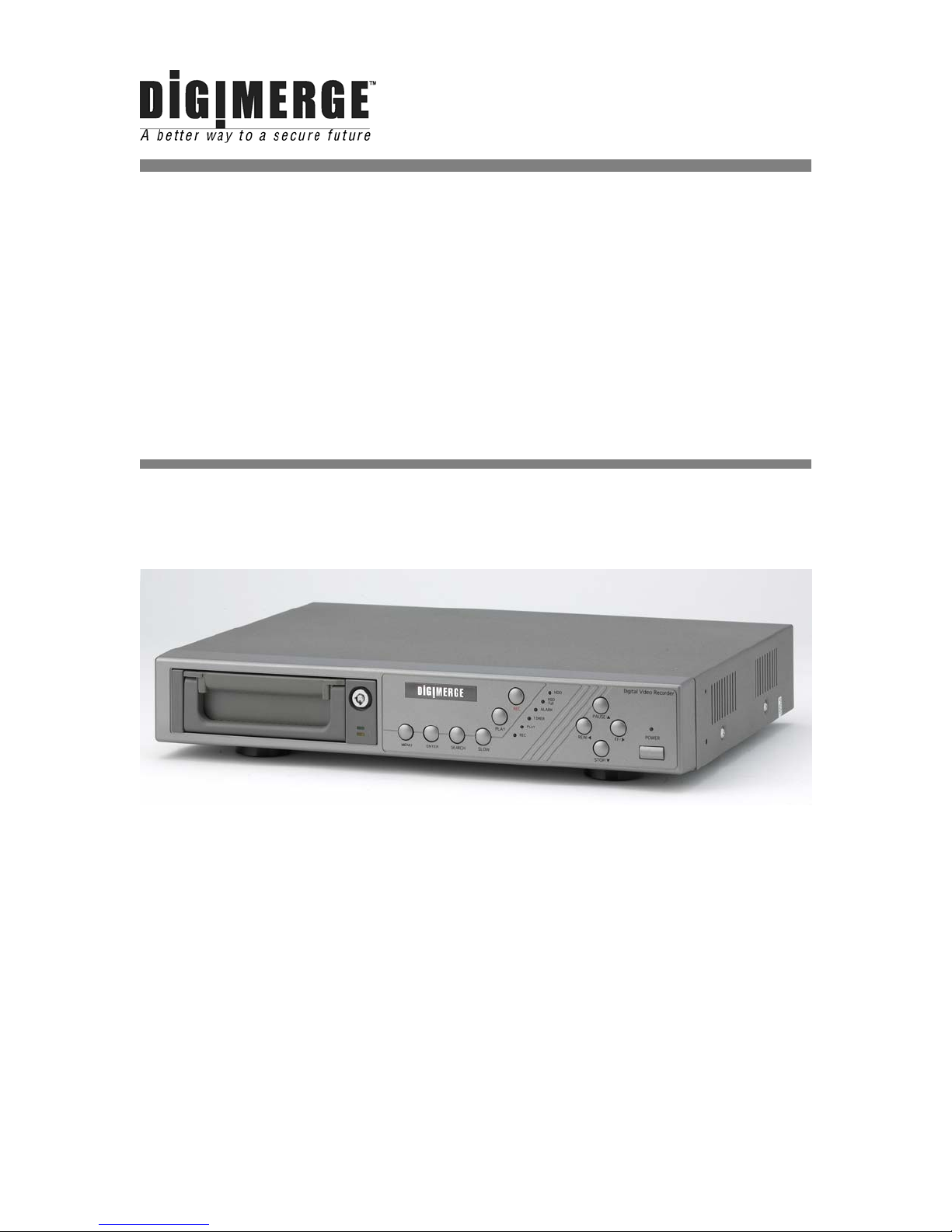
Digimerge Technologies Inc.
Single Channel
Digital Video Recorder
Models: DGR100/DGR101
Installation / User Manual
Page 2

Under the copyright laws, this documentation may not be copied, photocopied, reproduced,
translated, or reduced to any electronic medium or machine-readable form, in whole or part without
the prior written consent of Digimerge Technologies Inc., except in the manner described in the
documentation.
© Copyright 2003 Digimerge Technologies Inc.
300 Alden Road
Markham, Ontario
L3R 4C1 CANADA
All rights reserved. Printed in Taiwan.
THIS DEVICE COMPLIES WITH PART 15 OF THE FCC RULES.
OPERATION IS SUBJECT TO THE FOLLOWING TWO CONDITIONS:
INCLUDING INTERFERENCE THAT MAY CAUSE UNDERSIRED OPERATION.
1. THIS DEVICE MAY NOT CAUSE HARMFULL INTERFERENCE, AND
2. THIS DEVICE MUST ACCEPT ANY INTERFERENCE RECEIVED,
NOTE: This equipment has been tested and found to comply with the limits for a Class B digital device,
pursuant to part 15 of the FCC Rules. These limits are designed to provide reasonable protection against
harmful interference when the equipment is operated in a commercial environment. This equipment
generates, uses, and can radiate radio frequency energy and, if not installed and used in accordance with
the instruction manual, may cause harmful interference to radio communications. However, there is no
guarantee that interference will not occur in a particular installation.
Operation of this equipment in a residential area is likely to cause harmful interference in which case the
user will be required to correct the interference at one’s own expense.
CAUTION: CHANGES OR MODIFICATIONS NOT EXPRESSLY APPROVED BY THE PARTY
RESPONSIBLE FOR COMPLIANCE COULD VOID THE USER’S AUTHORITY TO OPERATE THE
EQUIPMENT.
1
Page 3

Table of Contents
Important Safety Instructions .......................................................................................................................... 3
Introduction ..................................................................................................................................................... 4
Features.......................................................................................................................................................... 4
System Contents............................................................................................................................................. 5
Getting Started................................................................................................................................................ 5
Front Panel Controls ....................................................................................................................................... 6
Accessing the Menu........................................................................................................................................ 8
Main Menu ............................................................................................................................................... 8
System Set Up ................................................................................................................................................ 9
Setting the Internal Alarm Buzzer ............................................................................................................ 9
Setting the Hard Drive Overwrite ............................................................................................................. 9
System Time/Date Set up.......................................................................................................................10
Changing the System Password.............................................................................................................10
Clearing the Hard Drive Data..................................................................................................................11
Resetting System to Factory Defaults.....................................................................................................11
Other Menu Options.......................................................................................................................................12
Timer Recording Setup ...........................................................................................................................12
Record Settings ......................................................................................................................................12
Alarm Setup ............................................................................................................................................13
Remote Protocol Setup...........................................................................................................................13
Event Log Viewing ..................................................................................................................................14
System Operation ..........................................................................................................................................15
On Screen Display (OSD).......................................................................................................................15
Recording Methods.................................................................................................................................15
Video Search ..........................................................................................................................................16
Playing Back Video.................................................................................................................................16
Key Lock.................................................................................................................................................17
Troubleshooting .............................................................................................................................................18
Technical Specifications ................................................................................................................................19
Appendix # 1: Hard Drive Installation.............................................................................................................20
Appendix # 2: Peripheral Video Connections.................................................................................................23
Appendix # 3: External I/O Connections ........................................................................................................24
Rear Panel Connections .........................................................................................................................24
Pin Connections for COM Port and Alarm Block.....................................................................................25
Appendix # 4 - Recording Times (in hours)....................................................................................................26
2
Page 4
Important Safety Instructions
All the safety and operating instructions should be read before the appliance is operated. The
improper operation may cause irreparable damage to the appliance.
Please lift and place this equipment gently.
Do not expose this equipment under to direct sunlight.
Do not use this equipment near water or in contact with water.
Do not spill liquid of any kind on the equipment.
Do not unplug the power connector before turn the power off correctly.
This equipment should be operated using only the power source from standard package.
Unauthorized repair or parts substitutions may result in fire, electric shock or other hazards.
Do not switch the Power On & Off within short period (within 3 seconds).
Do not attempt to service this equipment by yourself. Refer all servicing to qualified service personnel.
This unit should be operated only from the type of power source indicated on the manufacturer’s label.
This installation should conform to all local codes.
CAUTION
RISK OF ELECTRIC SHOCK. DO NOT OPEN.
CAUTION: TO REDUCE THE RISK OF ELECTRIC SHOCK, DO NOT
REMOVE COVER (OR BACK). NO USER-SERVICEABLE PARTS
INSIDE. REFER SERVICING TO QUALIFIED SERVICE
PERSONNEL.
!
3
Page 5

Introduction
The DGR100/101 Digital Video Recorder (DVR) converts analog video to digital images and records them
on a removable hard disk drive.
The DVR offers many advantages over traditional time lapse VCR’s, allowing you to quickly access and
search for a specific time segment or event which has been recorded. This high quality recorded video can
be viewed at various playback speeds as well as frame-by-frame with the Jog Button feature. All this without
the need to replace video tapes.
To learn more about Digimerge products, please visit our website at www.digimerge.com.
Features
• Up to 45 Hour Real Time / 2755 Hour Time Lapse Recording (with 120 GB HDD)
• Multiplexer compatible (most models)
• On Screen Display and Real Time Clock Function
• High Quality Picture with Wavelet Compression Format
• 4 Adjustable Video Quality Settings
• Manual, Alarm, and Timer record options
• Search by Time, Event, or Alarm list
• Fast / slow forward and reverse searching function
• Security password protection
• Supports 20-120 GB HDD
• Alarm I/O terminal block
• RS232C communication port
• Automatic video loss detection
• Emergency back up battery feature
4
Page 6
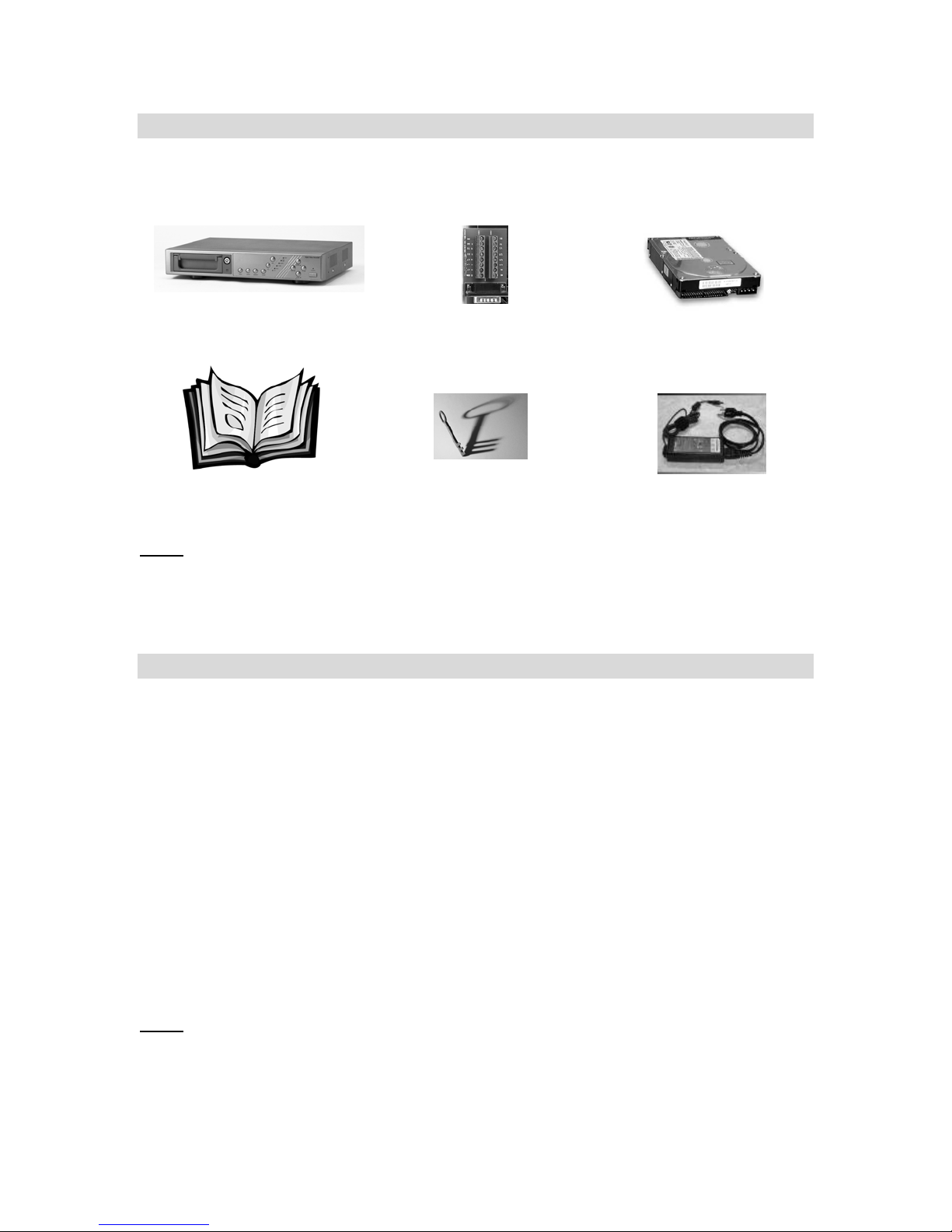
System Contents
The DGR100/101 box should include the items listed below. Please take a moment to verifty that no items
are missing from the package.
Single channel DVR
Installation / User
NOTE:
Manual
KEEP THE KEYS IN A SAFE PLACE. THEY ARE NECESSARY FOR INSTALLATION /
REMOVAL OF THE HARD DISK DRIVE.
Alarm Block
2 Keys for
Hard Drive Cartridge
Hard Disk Drive
(not included with all models)
Power Adapter and Cord
Getting Started
If the purchased DVR model did not contain a hard disk drive, please refer to Appendix #1 for HDD
installation instructions.
1. Connect video sources and monitor(s) following one of the configuration examples shown in
Appendix # 2.
2. Connect the AC Power Cord to the Power Adapter and plug into an electrical outlet. A Red LED
indicator light will be ON to indicate that the DVR is in Standby mode.
3. Press the Power button. The POWER LED will turn from red to orange, and other red LED
indicators will turn ON. Note: the system takes approximately 5 to 15 seconds to power up. During
the power-up, you will see the following messages: “HDD Detecting”, followed by “Master HDD
Connected”.
Once connected, the POWER LED will change to green, and red indicator lights be ON next to the Alarm
and Timer buttons.
IF YOU GET THE MESSAGE “HDD NOT FOUND”, PLEASE SEE APPENDIX #1 AS THE HDD
NOTE:
IS LIKELY NOT INSTALLED CORRECTLY.
5
Page 7
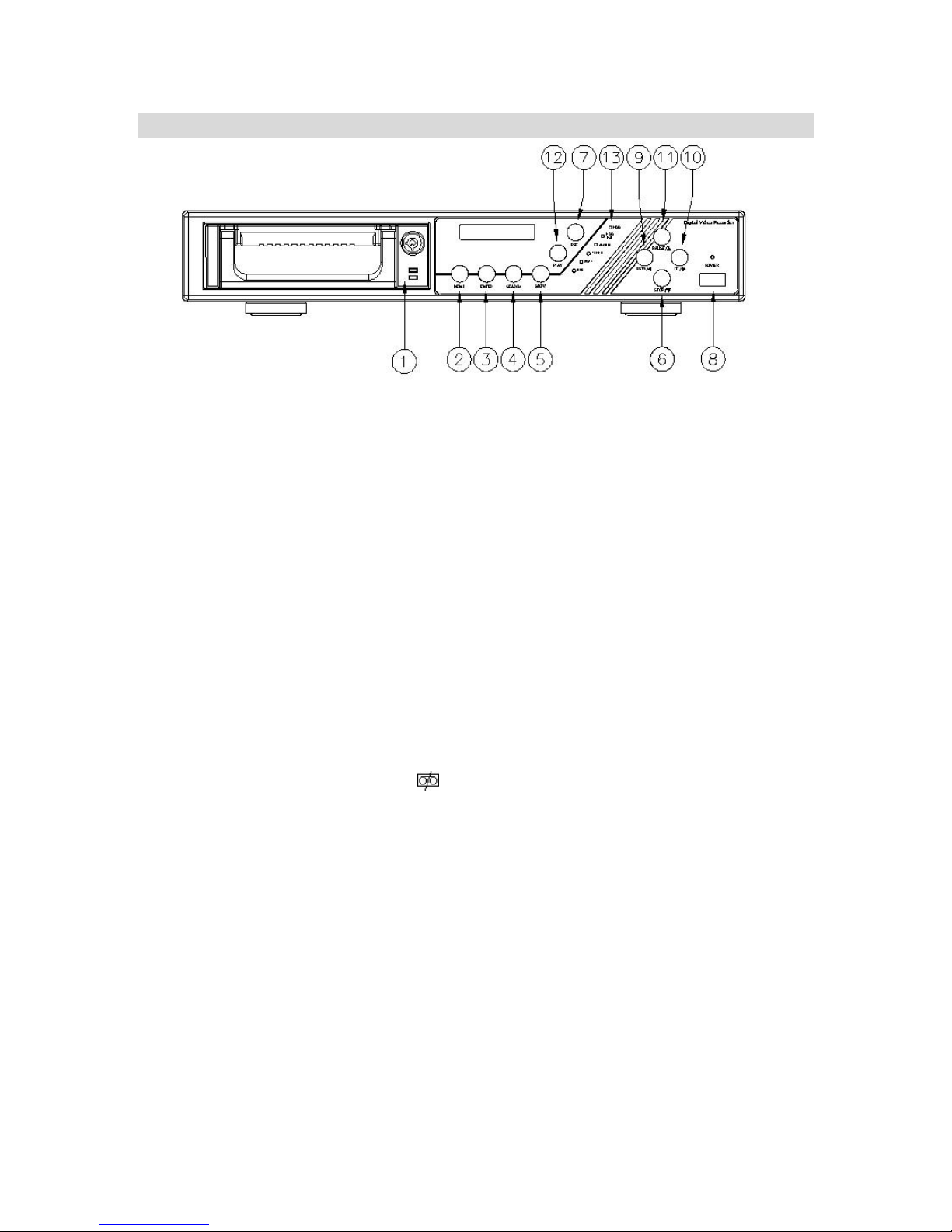
Front Panel Controls
1. Removable Cartridge Casing.
The DVR comes with a removable hard disk drive tray.
2. MENU
Press MENU to enter the Main Menu. You will be prompted for a password upon pressing the
MENU button. Please see section entitled ‘Accessing the Menu’ for further information
3. ENTER
Press ENTER for confirmation when making selections in Menu mode.
4. SEARCH
The SEARCH feature allows you to find recorded video. You can search video recordings by Time,
Date, or Alarm. Please see the ‘Video Search’ area under ‘System Operation for more information.
5. SLOW
Press SLOW to slow down the speed of Play mode. It can also be used to slow down the speed of
Fast Forward and Rewind.
6. STOP / ▼
(i) Pressing STOP terminates recording or playing. The DVR returns to live monitoring mode and
stops all other actions.
(ii) In Menu mode, the button is used to scroll Down through options.
7. REC
Press REC to start recording. The
recording is in progress.
8. POWER
Press POWER to turn the DVR system ON and OFF.
9. REW / ◄
The rewind button serves two functions:
(i) Pressing REW plays video backwards at a high speed.
(ii) In Menu mode, the button is used to scroll Left through options.
10. FF / ►
The fast-forward button serves two functions:
(i) Pressing FF plays video forwards at a high speed.
(ii) In Menu mode, the button is used to scroll Right through options.
11. PAUSE / ▲
The PAUSE button serves two functions:
(i) Pressing PAUSE pauses the recorded video being played on screen.
(ii) In Menu mode, the button is used to scroll Up through options.
icon will appear in the top-right corner of the screen when
6
Page 8

12. PLAY
Press PLAY to play recorded video. The DVR will play the last recorded video by default.
13. LED LIGHTS
Under the following condition, the Red LED Light is ON.
(1) HDD: blinks on startup after HDD is activated
(2) HDD Full: HDD has reached its capacity in memory
(3) ALARM: LED blinks during an alarm, remains ON when Alarm feature is set to “Enabled” in the
Menu
(4) TIMER: remains ON when Timer feature is set to “Enabled” in the Menu
(5) PLAY: during Play operation
(6) REC: during Recording operation
7
Page 9

Accessing the Menu
The Menu allows you to configure your DVR settings and program various recording options.
Follow these steps in order to access the Menu:
Press the MENU button. The password screen will appear:
The default Password is 0000. If you have not yet programmed or changed it. In this case, you can simply press
the Enter button to access the Menu.
To change the number of the Password, use the ◄ and ► buttons to scroll between numbers, and use the
▲and ▼buttons to change the value of the number that is blinking.
Press the ENTER button once the correct Password is entered. The menu options screen will appear.
Note: If you get a message “Password Error”, you have entered an incorrect password.
Main Menu
There are 6 options available in the Main Menu:
Timer: Programs specific times that you want the DVR to record
Record: Controls the speed, quality and mode of recording
Alarm: Programs Alarm duration and recording during an Alarm
Remote: Chooses interface for remote protocol via computer
System: Sets the date, chooses an HDD overwrite setting, changes
Password, resets system settings, or clears the HDD
Event: Allows you to view video from a list of recorded events
Navigating the Menu:
▲ and ▼: Scroll up and down through menu options; change values when an option is selected and is
blinking
◄ and ►: Scroll sideways within a menu option that has been selected
ENTER: Selects a submenu / an option in a submenu for browsing / modification
MENU: Completes modification of a menu option; exits a menu
The Menu setup will timeout after 1 minute of no key presses.
NOTE:
Password: 0000
(Menu)
Timer
Record
Alarm
Remote
System
Event
8
Page 10

System Set Up
From the Main Menu, select System then press ENTER.
Setting the Internal Alarm Buzzer
To enable or disable the internal alarm buzzer:
1. On the System screen, press ▲ or ▼ to select Buzzer, then press ENTER.
2. Press ▲ or ▼ to enable or disable the internal alarm buzzer. Options are:
ON = Buzzer is on. When the DVR detects an alarm trigger a buzzer sounds to alert the user.
OFF = Buzzer is off.
3. Press MENU to confirm your change.
4. Press ▲ or ▼ to move to another field on the System screen or press MENU to exit.
(System)
► Buzzer : On
HDD Overwrite : No
Message Latch: On
Date Display : Y- M - D
Date : 2002-JUL-14(SUN)
Time : 22:38:29
New Password : xxxx
Clear HDD : No
System Reset : No
Setting the Hard Drive Overwrite
Use this option to select whether recording will stop when the hard disk is full or whether it will start writing
over previous recordings.
1. On the System screen, press ▲ or ▼ to select HDD Overwrite, then press ENTER.
2. Press ▲ or ▼ to enable or disable the hard drive overwrite option. Options are:
YES = The DVR will overwrite the data on the hard drive when the disk is full.
NO = The DVR will stop recording when the drive is full.
3. Press MENU to confirm your change.
4. Press ▲ or ▼ to move to another field on the System screen or press MENU to exit.
9
Page 11

System Time/Date Set up
Setting System Date
1. On the System screen, press ▲ or ▼ to select Date, then press ENTER.
2. Press ▲ or ▼ to choose a number, then press ◄ or ►to move to the next digit:
2002-JUL-17 (SUN), YY-MM-DD (Day)
3. Press MENU to confirm your change.
4. Press ▲ or ▼ to move to another field on the System screen or press MENU to exit
this screen and confirm the current operation.
Setting System Time
1. On the System screen, press ▲ or ▼ to select Time, then press ENTER.
2. Press ▲ or ▼ to choose a number, then press ◄ or ►to move to the next digit:
Time: 22:38:29 HH:MM:SS; Hour, Minute, Second
3. Press MENU to confirm your change.
4. Press ▲ or ▼ to move to another field on the System screen or press MENU to exit
this screen and confirm the current operation.
Selecting the Time/Date Display Format
1. On the System screen, press ▲ or ▼ to select Date Display, then press ENTER.
2. Press ▲ or ▼ to choose a display format. Options are:
Y-M-D = Year - Month - Day
M-D-Y = Month - Day - Year
D-M-Y = Day – Month - Year
Off = The date and time will not show on the screen.
3. Press MENU to confirm your change.
4. Press ▲ or ▼ to move to another field on the System screen or press MENU to exit this screen
and confirm the current operation.
Changing the System Password
1. On the System screen, press ▲ or ▼ to select New Password, then press ENTER.
2. Press ▲ or ▼ to choose a number, then press ◄ or ► to move to the next digit:
3. Press MENU to confirm your change.
4. Press ▲ or ▼ move to another field on the System screen or press MENU to exit this screen and
confirm the current operation.
5. If you have completed all your system configuration changes, press MENU again to exit and close
menu setup.
10
Page 12

Clearing the Hard Drive Data
This option will erase all data from the hard drive. Ensure that there are no important recordings on the
disk before using this option.
1. On the System screen, press ▲ or ▼ to select Clear HDD, then press ENTER.
2. Press ▲ or ▼ to choose YES to clear the HDD or NO to leave as is.
3. When you choose “Yes” on this option and press ENTER, it will prompt:
4. Press ►to confirm clearing, or ◄ to cancel.
5. Press MENU to confirm your change.
6. Press ▲ or ▼ to move to another field on the System screen or press
MENU to exit this screen and confirm the current operation.
All Data in HDD
Will Be Cleared
Are you sure?
(◄ : No ► : Yes )
Resetting System to Factory Defaults
Using the System Reset option will set all options back to factory default settings. Use the steps below to
perform this option.
1. On the System screen, press ▲ or ▼ to select System Reset, then press ENTER.
2. Press ▲ or ▼ to choose:
Yes = Confirm the system reset and load the default settings.
No = Do not reset the system at this time.
3. Press MENU to exit this screen and confirm the current operation.
4. If you have completed all your system configuration changes, press MENU again to exit and close
menu setup.
11
Page 13

Other Menu Options
Timer Recording Setup
On the Main menu, selecting the Timer option will allow you to set daily
schedules in which you would like the DVR to automatically record.
Pressing ENTER after scrolling to the Timer option will bring up the
following menu options:
TIMER
– Select the day, or days (Mon-Fri / Sat-Sun / Daily) of the week that you wish to
Day
automatic recording to occur.
Start
– Select the starting time for the recording.
End – Select the finishing time for the recording.
IPS – Images per second – see Record Settings
submenu for more details.
Timer Enable
recording to function.
NOTE:
– Enables / disables Timer
WHEN THE TIMER IS SET, THE REC LED INDICATOR WILL BE ON. ALTHOUGH THE LIGHT
MAY BE ON, THE SYSTEM IS NOT NECESSARILY RECORDING SINCE IT WILL ONLY
RECORD DURING ITS SCHEDULED TIME.
Day Start End IPS
Daily 01:00 02:00 Off
SUN 12:00 13:00 Off
MON 08:00 09:00 Off
MO~FR 00:00 01:00 Off
SA~SU 20:00 21:00 Off
JAN-01 15:00 16:00 Off
►Timer
Record
(Timer)
Timer Enable: No
(Menu)
Alarm
Remote
System
Event
Record Settings
On the Main menu, selecting the Record option will allow you to set the
quality and speed of recordings.
Pressing ENTER after scrolling to the Record option will bring up the
following menu options:
Record IPS
Quality
There are four Quality settings: Basic / Normal / High / Best.
Record Mode
The default setting is Field (recommended).
– Set the system to 60 Images Per Second to record in
real time. Other setting options are 30, 15, 8, 4, 2 & 1
IPS. Please refer to Appendix #4 for the different
recording times.
Note: 60 IPS is equivalent to 30 Frames Per Second (FPS). 1 IPS is equal to 0.5
FPS.
– Quality and IPS go “hand-in-hand” as higher quality picture is more attainable when IPS is
high.
Higher quality settings use larger file sizes thus reducing record time on
Note:
the HDD.
– Sets recording mode between Frame and Field. One frame is equal to two fields.
► Record IPS: 60
Record Quality: Normal
(Menu)
Timer
►Record
Alarm
Remote
System
Event
(Record)
Record Mode: Frame
12
Page 14

Alarm Setup
On the Main menu, selecting the Alarm option will allow you to set how the
system responds to an alarm event (trigger on external alarm input).
Please refer to Appendix 3 for information on connecting an external
alarm sensor.
Pressing ENTER after scrolling to the Timer option will bring up the
following menu options:
Alarm Enable
Alarm Duration – Set the amount of time for recording to occur during
Record IPS
Record Quality – Sets the Quality of recording during an Alarm.
Record Mode
– Enables / disables the Alarm feature.
an Alarm. The Default setting is 1 sec.
Available durations available are:
10 sec, 15 sec. 20 sec, 30 sec, 60 sec, 2 min,
3 min, 5 min, 10 min, 30 min, 60 min, Always
– Sets the Images Per Second of recording during an
Alarm. Default setting is 60 IPS.
Available IPS settings are: 60, 30, 15, 8, 4, 2 & 1.
Available settings are: Basic, Normal, High and Best
– Sets the Record Mode between Frame and Field for
recording during an Alarm. The default setting is Field.
(Menu)
Timer
Record
►Alarm
Remote
System
Event
(Alarm)
►Alarm Enable: Yes
Alarm Duration: 1 MIN
Record IPS: 60
Record Quality: High
Record Mode: Frame
Remote Protocol Setup
If wishing to control the DVR remotely from a PC over an RS-232/RS-485 connection, this setup menu will
allow you to set the basic protocols for that connection.
Please refer to Appendix 3 for information on the Pin connections and command protocols that would be
used in this application.
Pressing ENTER after scrolling to the Timer option will bring up the
following menu options:
Remote Mode
Baud Rate – Selects the Baud rate (bps) to be used for the connection.
Available settings are: 115200, 57600, 19200, 9600, 3600, 2400, 1200
ID
– Selects a numerical number representing the remote protocol ID if required.
Available setting: 000 – 999
The remote connection on the DVR uses 8 data bits, 1 start bit, and 1 stop bit.
Below is an example of the data stream with the control codes shown.
ACT – OxFF OxCO ID CODE STOP – Ox7F
- Selects whether to use an RS-232 or RS-485 interface.
(Menu)
Timer
Record
Alarm
►Remote
System
Event
13
Page 15

The table below shows the available keypad functions when using the RS-232/485 controls.
FUNCTION
MENU
ENTER
SEARCH
SLOW
UP / PAUSE
CODE
0x4D
0x0D
0x48
0x53
0x55
KEY
M
ENTER
H
S
U
FUNCTION
DOWN / STOP
LEFT / F.F.
RIGHT / F.R.
PLAY
RECORD
CODE
0x4E
0x4C
0x52
0x50
0x72
Event Log Viewing
On the Main menu, selecting the Event option will allow you to view a log
history of system events.
An “Event” occurs when 1 of 3 incidents occur: a loss in Power, a
loss in Video, or a HDD error.
This submenu displays a list of Events that disabled recording in
order of their occurrence by Time and Date.
PWR – The time that Power returned after a Power failure.
VLS – The time that the Video input was lost.
HDD – The time that the HDD experienced an error.
◄: Page Up ►: Page Down – Scroll between pages of Events
by pressing the arrow buttons.
PWR 2002-JAN-01 03:00:00
VLS 2002-JAN-01 01:02:04
HDD 2002-JAN-01 01:02:03
PWR 2002-JAN-01 01:02:02
VLS 2002-JAN-01 01:02:01
HDD 2002-JAN-01 01:02:00
◄: Page Up ►: Page Down
Remote
►Event
KEY
N
L
R
P
r
(Menu)
Timer
Record
Alarm
System
14
Page 16

System Operation
On Screen Display (OSD)
The DGR100/101 will display all current status on the OSD.
Here is an example of the display.
The following status will be shown:
Time and Date
line.
Record Type
M= Manual, T= Timer, A= Alarm, E= External Trigger
Record Status
recording
HDD Status
or OW to indicate that it is set to Overwrite.
– The current time and date will be shown on the first
– The current recording method will be shown:
– A icon will be displayed when the unit is currently
– This will display either the remaining HDD capacity in GB
Recording Methods
The DGR100/101 allows multiple recording modes for maximum flexibility. The available recording options
are as follows:
1. Manual Recording
recording will override timed recording.
2. Timer Recording
Set-up’ section for information on how to set schedules.
3. Alarm Recording
may be connected to set the unit into alarm and activate recording. Refer to Appendix 3 for further
information on the alarm block connections.
4. External Trigger Recording
6) an external device may be used to trigger recording. Refer to Appendix 3 for more information on
the alarm block connections.
- This is activated by pressing the REC button on the front of the unit. Manual
- Allows daily scheduled recording times to be set. Refer to the ‘Timer Recording
- Using the A/I input on the included alarm terminal block (terminal 14), a sensor
- Using the REC START input on the included alarm block (terminal
2002 – JAN –01 01:02:03
E
32GB
15
Page 17

Video Search
The DVR allows you to easily find sections of recorded video using the Search feature.
Press the SEARCH button and you will see the following options:
Last Record: Plays the last recorded piece of video.
Full List: Shows a listing of all recorded video on the HDD, sorted by time.
Alarm List: Shows a listing of all recorded video triggered by an Alarm.
Time Search: Finds video recorded on a specific date that is entered.
►M 2002-JAN-01 01:02:03
M 2002-JAN-01 01:02:03
A 2002-JAN-01 01:02:03
T 2002-JAN-01 01:02:03
E 2002-JAN-01 01:02:03
M 2002-JAN-01 01:02:03
◄: Page Up ►: Page Down
An example of a Full List search is shown on the left.
Note that the date and time appear, along with the letter
representing the method of recording that took place.
Simply press ENTER to view a selected piece of video on
the list. The DVR will play that video, followed by the next
video in chronological order, until it hits the End of the list.
You can stop the video at any time by pressing the STOP
button.
►Last Record
Full List
Alarm List
Time Search
Playing Back Video
Pressing PLAY while in Normal operation will play back the most recently recorded video clip. The controls
below will allow you further controls over the playback whether in this mode or when viewing video from the
Search mode.
Fast forward - Press PLAY on the front panel, then press FF/► to open the fast forward search screen.
Press FF/► once to increase the speed to 2X, twice to increase the speed to 4X, and so
on. The maximum fast forward speed is 32X.
Fast Reverse - Press PLAY on the front panel, then press REW/◄ to open the fast reverse search
screen.
Press REW/◄ once to increase the reverse speed to 2X, twice to increase the reverse
speed to 4X, and so on. The maximum fast rewind speed is 32X.
Slow forward - Press PLAY on the front panel, then press SLOW for slow play. Press FF/► to play
images at slow speed (1/2X). Press FF/► again to slow the speed to 1/4X. Continue to
press FF/► to slow down the speed. The minimum slow speed is 1/32X.
Slow reverse Press PLAY on the front panel, then press SLOW for slow forward. Press REW/◄ to play
images slowly forward (1/2X). Press REW/◄ again to slow the speed to 1/4X. Continue to
press REW/◄ to slow down the speed. The minimum slow forward speed is 1/32X.
Image Jog Press PLAY on the front panel, then press PAUSE to lock the current image on the
screen.
Press FF/► to select single image play. Each time you press FF/► the next image will
display. Continuing to press FF/► will result in forward image by image playback.
Pressing REW/◄ will result in reverse image by image playback.
Pause Press PLAY on the front panel, then press PAUSE/▲ to lock the current image on the
screen.
Stop Press STOP on the front panel whenever you want to return the DVR to live monitoring
mode.
16
Page 18

Key Lock
For added security, you can “Lock” the buttons on your DVR. Locking disables the buttons and prevents
other people from using the system.
Press ENTER and MENU at the same time to enable Key Lock.
Press ENTER and MENU at the same time to disable Key Lock.
17
Page 19

•
•
•
•
•
•
•
Troubleshooting
HDD not found
No Power
Buttons aren’t working when pressed
No recorded video
Timer / Alarm recording isn’t working
No video
REC LED is ON, but video is not
recording
POSSIBLE SOLUTION PROBLEM
Need to insert HDD
• Make sure that the HDD Cartridge is locked, then
press any key to continue
Check the power source cord connections
• Check that there is power at the outlet
Check if the system is in Key Lock mode
• Press MENU and ENTER at the same time to
escape the Key Lock mode
Check that the HDD has been installed correctly
Check that Timer / Alarm Enable is set to YES
Check camera’s video cables and connections
• Check monitor’s video cables and connections
• Make sure that the camera is receiving power
It is set in Timer mode and will only record at the
scheduled time.
18
Page 20

Technical Specifications
HDD STORAGE
AUDIO
RECORD MODE
PLAYBACK SEARCHING
RS232
O.S.D. (On Screen Display)
SECURITY
VIDEO INPUT
VIDEO OUTPUT
VIDEO RESOLUTION
VIDEO COMPRESSION
DISPLAY REFRESH RATE
RECORD REFRESH RATE
ALARM INPUT
ALARM OUTPUT
VIDEO LOSS DETECTION
TIME DISPLAY FORMAT
POWER SOURCE
POWER CONSUMPTION < 27W
DIMENSIONS
WEIGHT
OPERATION TEMPERATURE
IDE type, UTMA 66 above, 1 removable HDD supported, 40 – 120GB
Available on DXR1100 / SXR1100 / DGR1100 models only
Manual / Alarm / External / Timer
Date & Time / Event / Alarm searching
Yes
Yes
Password protected
1 video input, composite 1 Vp-p / 75ohm (BNC)
1 video output , composite 1 Vp-p/75ohm (BNC)
720 x 486
Wavelet
60 ips (NTSC)
60 ips (NTSC)
TTL input, High (5V), Low (GND)
COM, NO
Yes
Yes
AC90~240V (included)
14.6” x 10.5” x 2.5” (380 x 270 x 65mm)
10 lbs (5 kgs)
50°F ~ 104°F (10 ~ 40°C)
19
Page 21

Appendix # 1: Hard Drive Installation
The compartment located on the front panel of the DVR is the removable Cartridge Casing where the HDD
is inserted. The various parts of the Cartridge Casing are labeled for your reference.
1. Remove the Cartridge Casing from the DVR
Lift the Handle and pull towards you. The Cartridge Casing will slide out of the DVR.
NOTE:
YOU MAY FIND THAT THE CARTRIDGE CASING IS LOCKED. IN THIS CASE, SKIP
AHEAD TO STEP 7 TO FIND INSTRUCTIONS ON UNLOCKING THE CABINET, THEN
RETURN TO STEP 2.
2. Remove the Cover from the Cartridge Casing
a) Unclip the release latch with the word “OPEN” printed beside it by gently pushing on the latch.
b) Slide the cover off the Cartridge Casing.
1. Keyhole
2. LED indicator lights
(Power indicator & HDD Access indicator)
3. Handle
20
Page 22

3. Connect the HDD into the Cartridge Casing
Take the Hard Disk Drive and connect the two cables from the back of the Cartridge Casing to the HDD.
The cables should be pushed in firmly, but not forcibly.
NOTE:
Ensure that the jumper on the back of the HDD is set to ‘Master’ or ‘CS (Cable
Select)’. Please refer to the label on the HDD for the correct settings, as these will
vary dependant upon model and manufacturer.
4. Secure the HDD in the Casing (optional)
Insert the six supplied screws (found in empty cartridge) and tighten them, positioning the HDD into
place. This step is optional, but it is recommended.
5. Slide the top Cover over the Cartridge Casing
Slide the Cover forward over the Cartridge Case. Ensure it is secured in place over the release latch.
21
Page 23

6. Reinsert the Cartridge Casing into the DVR
A
7. Lock the Cabinet
Lock the cabinet by inserting the supplied key and turning clockwise.
(locked)
NOTE: IF YOU DO NOT LOCK THE CABINET, THE DVR SYSTEM WILL NOT FUNCTION PROPERLY.
B
(unlocked)
22
Page 24

Appendix # 2: Peripheral Video Connections
The diagrams below show examples of typical configurations where the following additional equipment may
be used:
• Single Video Camera
• Multiple video cameras using a multiplexer.
• Monitor
• Motion alarm sensor
• PC for RS-232 control
23
Page 25

Appendix # 3: External I/O Connections
Rear Panel Connections
The rear panel has basic connections for Power (4 Pin Din), Video In/Out (BNC connections) and the
External I/O port (9 Pin connector). Audio inputs (RCA inputs) are only available on DGR101 models.
.
The included alarm block (not shown) allows for easier connections when using external triggers and alarm
sensors.
Below are line diagrams of the alarm block and possible RS-232 connections. Appendix 1 shows a detailed
description of each Pin/Terminal is provided.
Alarm Block Diagram 9 Pin COM port connections
NO 8
NC 7
R/S 6
E/O 5
15 COM
14 A/I
13 A/R
12 D/F
25 Pin COM port connections
S/O 4
V/L 3
TX1 2
RX 1 1
11 RX2
10 TX2
9 GND
GND
24
Page 26

Pin Connections for COM Port and Alarm Block
PIN 1. RS232-TX : RS-232
RS-232 Transmit Data Pin. The DVR can be controlled remotely by an external device or control system,
such as a control keyboard or PC using RS-232 serial communication signals.
PIN 2. RS232-RX : RS-232
RS-232 Receive Data Pin. DVR can be controlled remotely by an external device or control system, such as
a control keyboard or PC using RS-232 serial communications signals.
PIN 3. VIDEO LOSS
When video loss happens, it will send a signal to trigger another accessory.
This pin output becomes “Low” when video loss occurs, and remains “High” under normal operation.
PIN 4. SWITCH OUT
Connect to VCR trigger recording terminal of multiplexer, in order to synchronize recording signals. The
default mode is falling (Negative) Edge.
PIN 5. ERROR OUT
When HDD errors happen, this pin will send a signal out.
This pin becomes “Low” when HDD errors occur, and remains “High” under normal operation.
PIN 6. REC START
This pin can accept an external trigger signal to activate record mode from an external device. When the
external signal turns to “Low”, it will trigger DVR record mode. When the external signal goes back to “High”,
it will stop recording.
PIN 7. EXTERNAL ALARM NC (Normally Closed)
Under normal operation, NC is connected with COM. When an alarm is triggered, COM disconnects with NC
(becomes open) for the duration of the alarm. (Form C Relay)
PIN 8. EXTERNAL ALARM NO (Normally Open)
Under normal operation, NO is open with respect to COM. When an alarm occurs, NO is connected to COM
(becomes closed) for the duration of the alarm. (Form C relay)
PIN 9. GND (GROUND)
PIN 10. RS485-B
The DVR can be controlled remotely by an external device or control system, such as a control keyboard,
using RS485 serial communications signals.
PIN 11. RS485-A
The DVR can be controlled remotely by an external device or control system, such as a control keyboard,
using RS485 serial communications signals.
PIN 12. DISK FULL
Under normal operation, this Pin remains “High”. When the hard drive is full, this pin will provide a “Low”
trigger state.
This may be used to trigger a second DVR to begin recording when the hard drive has filled.
PIN 13. ALARM RESET
When this pin ( PIN 13 ) is connected to GND ( PIN 9 ), any alarm notification (Buzzer, LED) on the DVR will
be reset.
PIN 14. ALARM INPUT
When this pin ( PIN 14 ) is connected to GND ( PIN 9 ), the DVR will start recording and the buzzer will be
on.
PIN 15. COM
Under normal operation COM connects with NC (Pin 7). When the alarm is triggered, COM disconnects with
NC, and connects with NO. (Form C relay)
25
Page 27

Appendix # 4 - Recording Times (in hours)
Expected Times based on a 120 GB HDD
Expected Times based on a 80 GB HDD
Expected Times based on a 40 GB HDD
IPS 60 30 15 8 4 2 1
Best
High
Normal
Quality
Record
Basic
13.5 27 55.5 93.5 207 415.5 832.5
18 36 73.5 138 277.5 555 1110
27 55.5 111 207 415.5 831 1662
45 91.5 184.5 346.5 694.5 1389 2775
IPS 60 30 15 8 4 2 1
Best
High
Normal
Quality
Record
Basic
9 18 37 69 138 277 555
12 24 49 92 185 370 740
18 37 74 138 277 554 1108
30 61 123 231 463 926 1850
IPS 60 30 15 8 4 2 1
Best
High
Normal
Quality
Record
Basic
4.5 9 18.5 34.5 69 138.5 277.5
6 12 24.5 46 92.5 185 370
9 18.5 37 69 138.5 277 554
15 30.5 61.5 115.5 231.5 463 925
26
Page 28

Digimerge Technologies Inc.
300 Alden Road
Markham Ontario
L3R 4C1
www.digimerge.com
rev04
27
 Loading...