

Page 1
ATTENTION:
Broadband Rou ter
and Compute r are
required for l ocal and
remote moni toring
(not included).
INSTRUCTIONS:
For detail ed setup
informat ion, please
refer to your U ser’s
manual.
SOFTWARE
REQUIREMENT S:
For DigiCli ent Soft ware
requiremen ts, please refer
to the Sof tware User ’s
manual.
Check Page
11
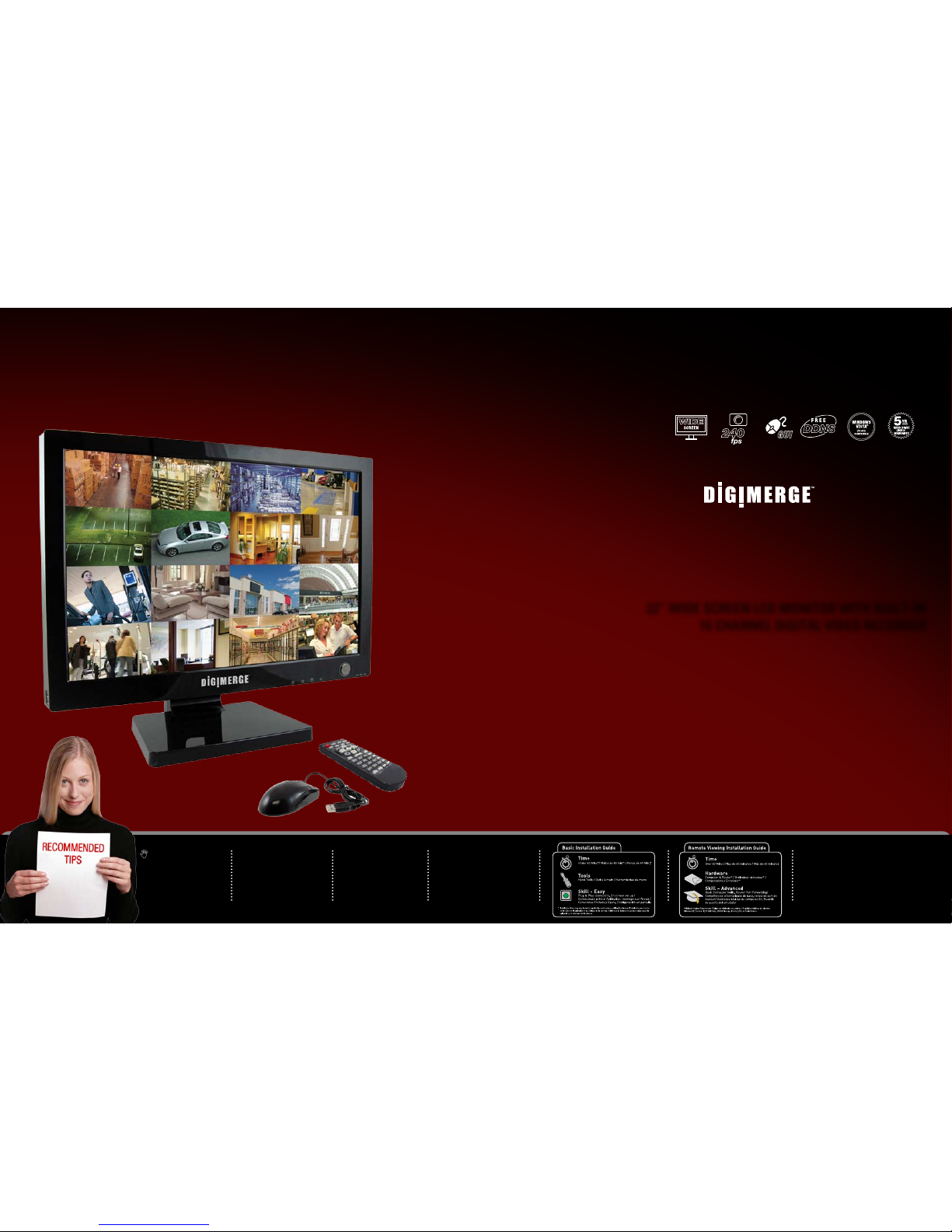
• 22” LCD DVR
• Power Adaptor
• Remote Control
• Mouse
• Ethernet Cable
• Octopus Cable
PACKAGE CONTENTS:
• Quick Start Guide
• Software CD
• Cleaning Cloth
ATTENTION:
*Number of channels ,
cameras and hard dr ive
capacity may va ry by
model. Check you r
package for specifi c
content in formation.
INFORMAT ION IN THIS DOCUME NT IS SUBJEC T T O
CHANGE WITHOU T NOTI CE. AS OUR P RODUCTS ARE
SUBJEC T TO CONT INUOUS IMPRO VEMENT, DIGIMERG E
TECHNOL OGIES INC. AND OUR SUBSIDIA RIES RESERV E
THE RIGHT TO MODIF Y PRODUCT DESIGN, SP ECIFICATIONS AND PR ICES, WITH OUT NOTICE A ND WITHOU T
INCURRING ANY OBLIG ATION. E&OE © 20 08 DIGIMERG E.
ALL RIGHT S RESERVE D.
ALL-IN-ONE PROFESSIONAL DIGITAL
SURVEILLANCE RECORDING SYSTEM
Designed for Business or Home with
multi-purpose display applications
22” WIDE SCREEN LCD MONITOR WITH BUILT-IN
16 CHANNEL DIGITAL VIDEO RECORDER
D221600 Series
Quick Start Guide
Page 2
ww w.dig imerg e.com
D2 2160 0 S ERI ES Q uic k St art Gui de_ R1 P age 2
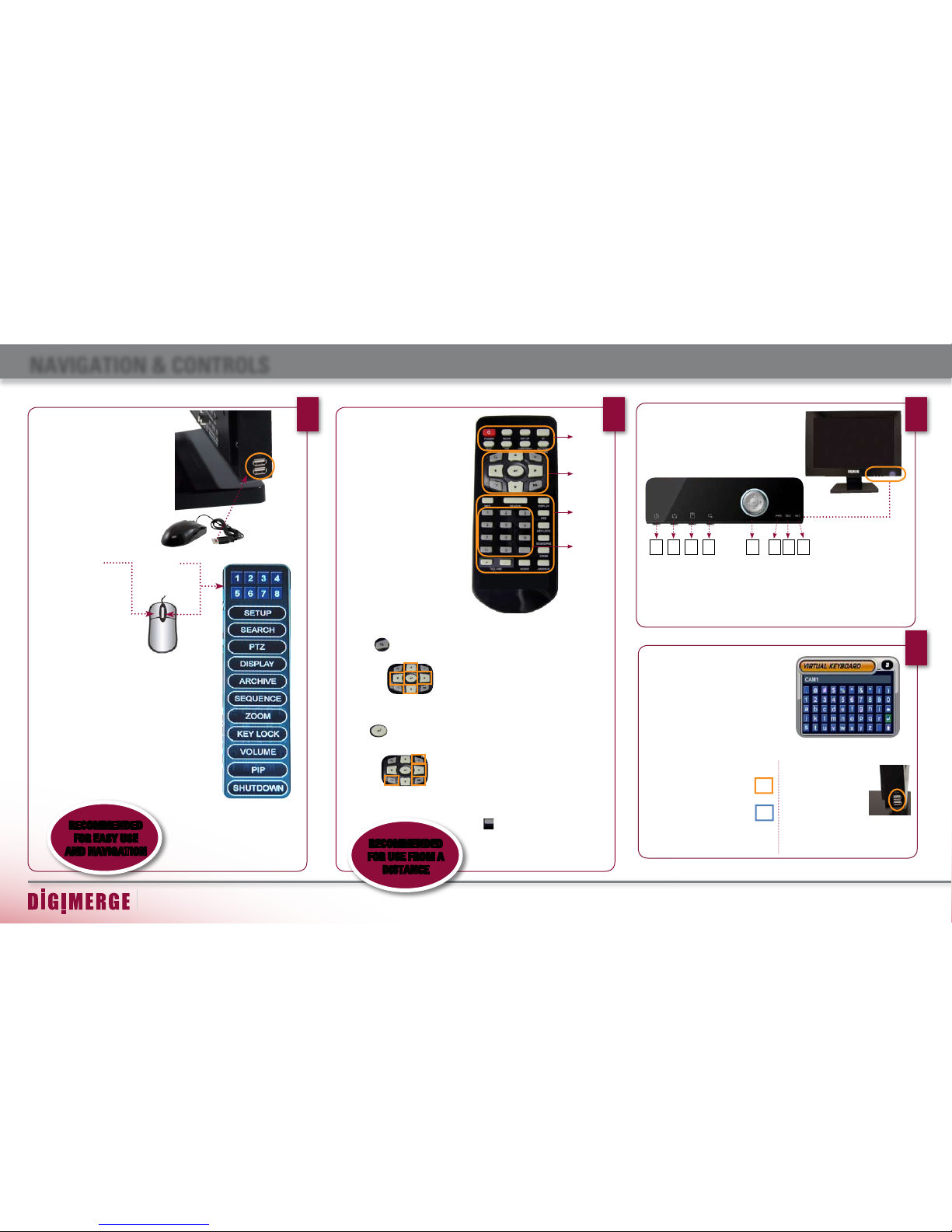
NAVIGATION & CONTROLS
This System has been designed to
use a Mouse as a primary mode
of navigation and configuration.
Connect a mouse to one of the
USB ports located on the side of
the unit before powering on the
system.
The mouse behaves in the same
way as a PC mouse - use the Left
and Right Buttons to open menus
and change options.
MOUSE:
1
LEFT BUTTON -
• Click to select options
in Menu, Recording and
Search Mode.
• Click to change settings,
select dates and perform
other options.
• Double click on a Channel
in QUAD or other disply
views to view the single
camera in full screen.
RIGHT BUTTON -
• Opens a submenu
to access a list of
options:
RECOMMENDED
FOR EASY USE
AND NAVIGATION
REMOTE CONTROL:
2
RECOMMENDED
FOR USE FROM A
DISTANCE
The Remote Control can also be used
as a primary mode of navigation and
configuration.
Listed below is a quick reference of
buttons and their functions.
Group 1
POWER: Press the Power Button to turn
off the Monitor Display. Press and hold
the button for 3 seconds to shut down
the entire system.
MODE: Press the Mode Button to display
the Multi-Function Mode Menu.
SETUP: Displays the Setup Menu.
ID: For using one remote to control
multiple systems. Refer to user manual.
DVR: Change to DVR Mode.
VGA: Change to VGA Mode.
COMPONENT: Change to Component
Mode.
PICTURE FRAME: Change to Picture
Frame Mode.
Group 2
RETURN:
Exits from a System
Menu.
NAVIGATION:
Press the Navigation Controls to move
Up, Down, Left or Right in System and
Mode menus.
ENTER:
Press the Enter Button to
select an option in the System Menu or
Multi-Function Menu.
PLAYBACK:
Use the Playback controls to Pause, Play,
Reverse or Fastforward the Playback in
DVR Mode.
Group 3
INFO: Displays the System Information in DVR
Mode.
SEARCH: Displays the Video Playback Search
menu
DISPLAY: Switches the display to single, quad and
multi-screen views.
PTZ: Switches to PTZ Mode.
KEYLOCK: Locks the Front Panel buttons.
SEQUENCE: Changes the Monitor Display to
Sequence through channels (based on menu settings).
ZOOM: Displays one channel with Digital Zoom.
ARCHIVE: Displays the Archive menu.
AUDIO: Switches between live audio channels
(CH1~4 only). Press Audio & channel number.
VOLUME +/-: Increase or Decrease the volume of
the camera currently broadcasting live audio.
Group 4
NUMBER KEYPAD (1 - 9, 1-, 0): Use to switch
between Cameras in live view mode
PIP:
Displays a Picture In Picture Screen. Press
again to exit the PIP option
3
MONITOR FRONT PANEL:
The Front Panel buttons can also be used to access
the menus and configure the system.
• Navigation Controls - Move Up/Down/Left/Right.
• Enter Button - Press this button to select and change
the values in a menu option.
1. SYSTEM POWER BUTTON
2. MULTI-FUNCTION MENU MODES
Press the Multi-Function Menu button to
switch between monitor modes:
• DVR Mode • VGA Mode • Component
Mode • Picture Frame Mode • Installation
Guide
1 2 3 4 5 6 7 8
3. SETUP MENU
4. RETURN BUTTON
5. NAVIGATION & ENTER CONTROLS
6. POWER LED
7. RECORD LED
8. NETWORK LED
4
The Virtual Keyboard control becomes available
when keyboard input (A~Z, 0~9) is needed for
entering information such as Names, Network
Information, etc.
• Navigate using the arrow keys on the Front Panel
or Remote Control or using the Mouse menu.
• Use the ENTER key to choose the letters and
numbers.
Active Option Indicator:
Orange Highlight - Indicates that
the option is in active editing
mode.
Blue Highlight - Indicates that
the option is available for editing.
Once the option is highlighted,
press the ENTER key to edit the
option (hightlight changes to
Orange).
USB Ports:
Provides connection ports
for USB Flash Drives
(thumbsticks), USB
Mouse (included), & USB
Hard Drives or CDRW/
DVDRW optical drives.
VIRTUAL KEYBOARD CONTROL:
GROUP 1
GROUP 2
GROUP 3
GROUP 4
PIP
PIP
PIP
Page 3
ww w.dig imerg e.com
D2 2160 0 S ERI ES Q uic k St art Gui de_ R1 P age 3
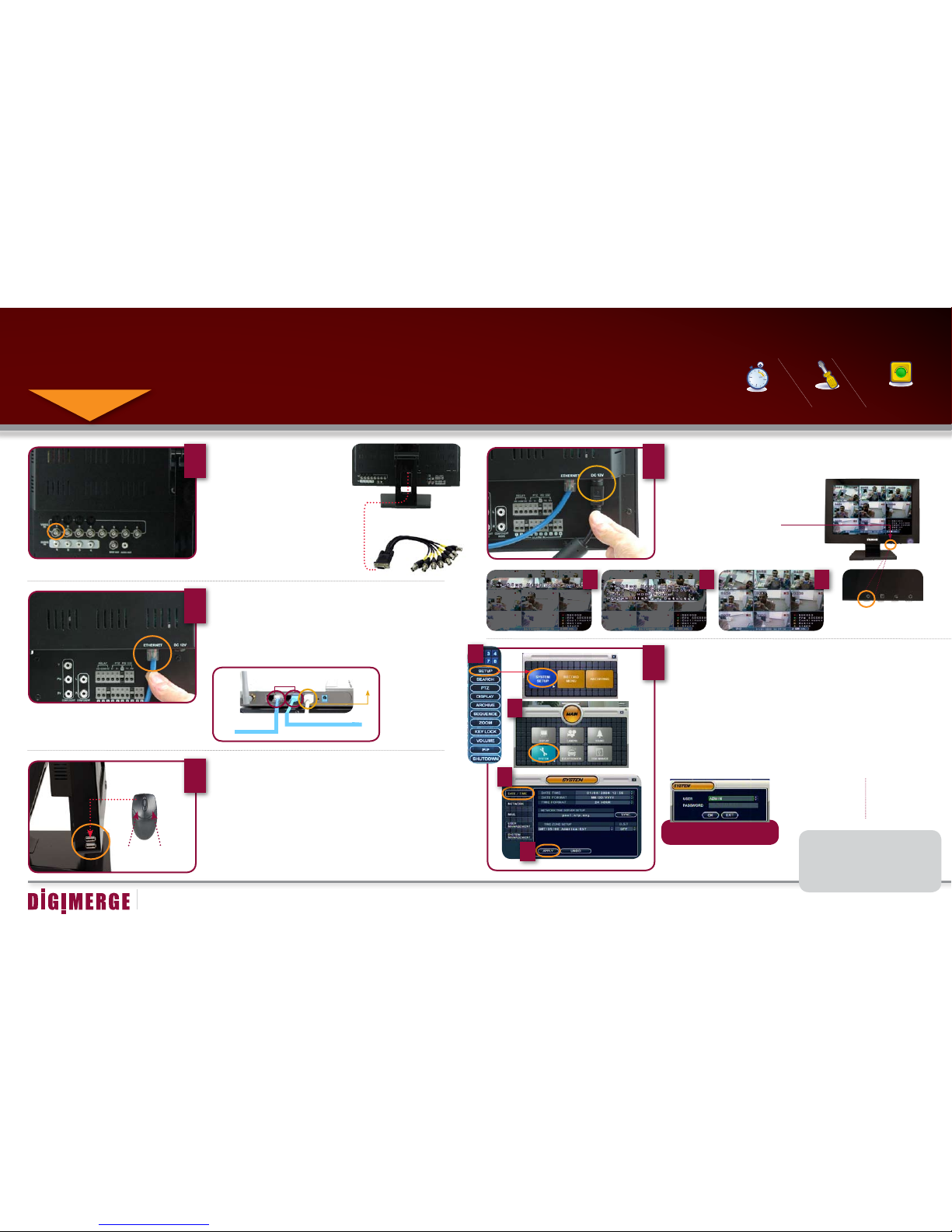
SET UP YOUR MONITOR FIRST
STEP 1
2
Connect one end of the Ethernet cable (for remote
monitoring) to one of the router’s (not included) LAN
ports and the other end to Monitor’s Network Port
located at the back of the Monitor.
See picture below showing a generic LAN/WAN
connection.
Connect Ethernet Cable:
WAN (WIDE
AREA NETWORK)
LAN (LOCAL AREA NETWORK)
TO YOUR COMPUTER
TO YOUR MONITOR
BACK OF THE ROUTER
Connect Cameras to the Monitor:
Your can connect up to 16 BNC
cameras (not included) to your
system.
TIP: Test the cameras prior to selecting a permanent
mounting location by temporarily connecting the
Cameras and Cables to your System.
MAKE SURE THAT THE
DATE AND TIME ARE SET
PRIOR TO RECORDING!
*** NOTE: IF THE DATE/
TIME IS SET INTO THE
PAST, A MESSAGE WILL
APPEAR WARNING THAT
OVERLAPPED DATE(S)
WILL BE ERASED.
Congratulations!
You have completed Step 1 successfully.
You can now view, record and playback
images on your monitor.
4
Connect one end of the Power adaptor to the monitor,
the other end to an electrical outlet.
Connect Power Cable:
3
Connect a USB mouse to one of the USB
ports located at the side of the monitor.
Connect the Mouse:
LEFT
CLICK
RIGHT
CL
ICK
1
Set the Time and Date***:
5
THE DEFAULT USER IS ADMIN
THE DEFAULT ADMIN PASSOWRD IS 1234
NOTE: THIS MAY TAKE UP TO 15 SECONDS. PLEASE WAIT
UNTIL THE SYSTEM COMPLETES LOADING.
Your system will perform the following System Check:
1. Blue LED at the front flashes four times
2. You will hear 2 beeps
3. Power LED at the front turns RED
3
1 2
PRESS THE POWER BUTTON ON
Your system will load with screens shown below.
Monitor Front Panel - Power Button
under 30 minutesunder 15 minutes under 60 minutes
Hand Tools Hardware
Router
Hi Speed
over 60 minutes
Skill Level
Time
under 30 minutesunder 15 minutes under 60 minutes
Hand Tools Hardware
Router
Hi Speed
over 60 minutes
Time Tools Skills - Easy
Under 20 Minutes*
Hand Tools Plug & Play connectors,
On screen set up
* Installation time may vary based on
application and camera cabling
BASIC INSTALLATION GUIDE
Time and Date can be set by
• Pressing the SETUP button from the front panel of the monitor
• Pressing the SETUP button from the remote control (or) by
• Using the mouse navigation (recommended)
1. Right click the mouse and select SETUP and click on SYSTEM SETUP
2. On SYSTEM SETUP MAIN Menu, select SYSTEM
3. Click on the DATE/TIME menu and use the UP and DOWN arrows to
change the DATE/TIME.
4. Click Apply. The system will prompt you for default USER ID and
PASSWORD.
1
2
3
4
The Octopus Cable (provided with the system)
allows 8 additional BNC cameras to be added
to the system representing 9 and 16 channels.
Connect the first camera to the CH1
input. Follow the same steps to connect
the additional cameras.
Page 4
ww w.dig imerg e.com
D2 2160 0 S ERI ES Q uic k St art Gui de_ R1 P age 4
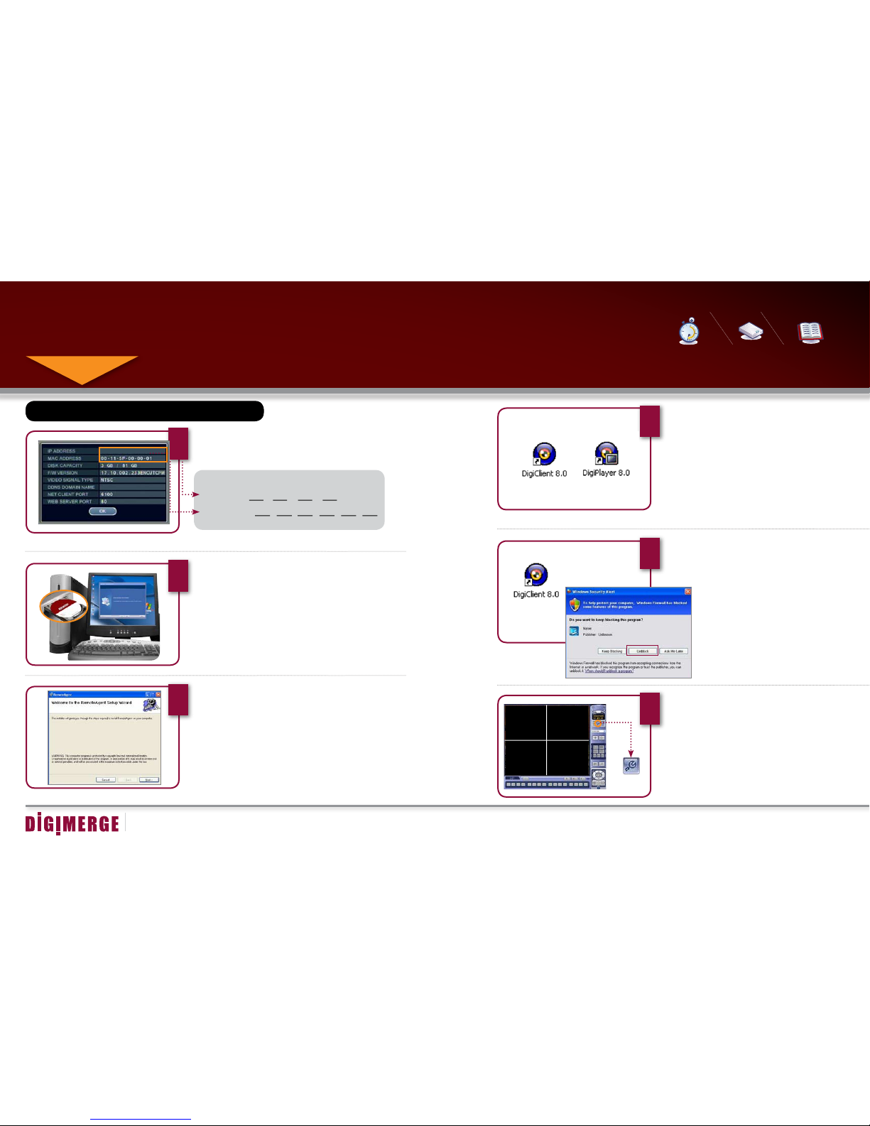
SET UP LOCAL VIEWING ON YOUR PC
STEP 2
*Your system MUST be connected to a Router prior to powering it ON.
THIS STEP RELATES TO REMOTE VIEWING OVER THE LAN (LOCAL AREA NETWORK)
BY USING A PC LOCATED ON THE SAME NETWORK AS THAT OF THE SYSTEM.
NOTE: The system will lease
networking information from
your Router. If you wish to
set your information manually, then remove the from
DHCP option. Please consult
your Hardware Manual for
further Menu options.
3
Follow the installation screens to complete
DigiClient Software installation.
DigiClient Software (on your local computer):
Retrieve System Information:
1
To retrieve the System Information, press the INFO button
on the Remote Control (ensure batteries are inserted) (or)
Press the ENTER button on the front panel of the Monitor.
Install Software (on your local computer):
Insert the DigiClient Software CD into
your local computer’s CD ROM drive
and proceed with the installation.
Record the IP and MAC Addresses in the section below:
IP ADDRESS : . . .
MAC ADDRESS : : : : : :
(Required for DDNS r egistration)
2
Computer - not included
5
Double-click the DigiClient software icon on your
desktop to run the program.
Run the DigiClient Software (on your local computer):
4
Close the CD Menu Screen. A DigiClient
icon and a DigiPlayer icon will appear on your
desktop.
DigiClient Software (on your local computer):
Set-up (on your local computer):
Click the Setup icon from the DigiClient Software Screen
6
SET-UP BUTTON
Router
Hi Speed
over 60 minutes
Time Skills - Intermediate
Plug & Play connectors,
On screen set up
Under 30 Minutes*
* Installation time may
vary based on application
Hi Speed
over 60 minutes
Hardware
Computer &
Router*
LOCAL VIEWING INSTALLATION GUIDE
192.168.1.12
* Minimum System Requirement:
Windows XP, Pentium IV, 256MB
Ram (512MB Recommended),
200MB Storage, High Speed
Internet, DSL or Cable Modem
If the IP Address is 127.0.0.1 it means that you are either not connected to your local
network or your system is not in DHCP detect mode.
NOTE: When you run DigiClient on your PC for the first
time, you may see the Windows Security Alert. Please click
unblock to run the application. (on Windows Vista™ select
“Allow”).
Please refer to your Software Manual for instructions about
using Digi Backup Player and Storage Calculator.
DIGIMERGE
Page 5

ww w.dig imerg e.com
D2 2160 0 S ERI ES Q uic k St art Gui de_ R1 P age 5
9
Select the new Group you created using the drop
down menu (1) and press the CONNECT button (2)
to connect to the LOCAL LIVE site.
DigiClient Software - Local Configuration
(on your local computer):
SET UP LOCAL VIEWING ON YOUR PC (CONTINUED)
STEP 2
Add ‘Group’ (on your local computer):
7
Click on the SITE listing on the Left Panel, and Right
Click to ‘ADD GROUP’.
Enter a name for the GROUP, and click OK.
OFFICE
Enter Setup Information (on your local computer):
Select the GROUP you created and
enter SETUP information.
8
7
System
192.168.1.12
6100
ADMIN
****
8
1. Enter a Name for the System
2. Enter the IP Address recorded in Step 2-1
3. Enter the Monitor TCP/IP port (6100 by default)
4. Enter the User ID (ADMIN by default), max. 5
characters
5. Enter the Admin Password (1234 by default)
* User ID and Password are case sensitive
6. Add cameras using the drop down menus to
assign camera positions. 1, 2, 3, 4 is set by default
7. Click ADD to add the System Location
8. Click OK
1
2
3
4
5
CONNECT BUTTON
1
2
LOCAL LIVE SITE
Congratulations!
You have completed Step 2 successfully.
You can now view, playback images
and remotely control your system on
your local computer over the Local Area
Network (LAN).
Camera Selection Drop down Menu
6
2
3 4
1
2
3
4
5
6
OFFICE
Page 6

ww w.dig imerg e.com
D2 2160 0 S ERI ES Q uic k St art Gui de_ R1 P age 6
SET UP INTERNET REMOTE SECURITY MONITORING
STEP 3
Create Account
3
From the http://ddns.digimerge.net website, click
the CREATE ACCOUNT option.
Create Account:
Port Forward Your Router:
1
Port forward your router first before proceeding with the set-up. You must forward
Ports: 6100 (TCP/IP)
80 (WEB)
All routers are different. To port forward your router, please refer to your router’s
user manual.
http://ddns.digimerge.net
DDNS (Dynamic Domain Name System) Set-up:
Open your web browser (Internet Explorer by default) and
enter http://ddns.digimerge.net in the address bar.
2
Enter DDNS Set-up on your System:
Mouse navigation (recommended)
An automated REGISTRATION CONFIRMATION
EMAIL will be sent to your email. Print and Save
this confirmation. You will need this information to
access your System remotely.
Registration Email:
1. FOR PRODUCT LICENSE select the D221600
Series option from the drop down menu.
2. FOR PRODUCT CODE enter the Monitor’s MAC
address (recorded in step 2, section 1).
3. FOR URL REQUEST enter a unique URL name
(e.g. tomsmith). Note: URL name should not be
more than 15 characters.
Complete New Account Information:
5
DNS Server Name: DIGIMERGE
Domain Nam e: tomsmith
User Name: tom smith
User Passw ord: (yo ur password)
DDNS Statu s: ----OK CANC EL
4
1
2
3
REMOTE VIEWING INSTALLATION GUIDE
Hi Speed
over 60 minutes
Time Hardware
Skills - Advanced
60 Minutes
Computer &
Router*
Basic Computer
Skills, Router Port
Forwarding
* Installation time may vary
based on application
Hi Speed
over 60 minutes
* Minimum System Requirement:
Windows XP, Pentium IV, 256MB
Ram (512MB Recommended),
200MB Storage, High Speed
Internet, DSL or Cable Modem
A router configuration guide featuring the most commonly used routers in the market
is available on your DigiClient Software CD.
An example of a port forwarding screen is shown for illustration purposes.
1. Right click the mouse and select SETUP and click
on SYSTEM SETUP
2. On SYSTEM SETUP MAIN Menu, select SYSTEM
3. Click on NETWORK to enable and add DDNS
information. See Step 7.
1
2
3
6
System
System
6100 6100
80 80
12
12
EXAMPLE
DIGIMERGE
Page 7

ww w.dig imerg e.com
D2 2160 0 S ERI ES Q uic k St art Gui de_ R1 P age 7
SET UP INTERNET REMOTE SECURITY MONITORING (CONTINUED)
STEP 3
Enable DDNS Settings:
7
On the NETWORK menu, use the DOWN arrow key to
navigate to DDNS. Highlight DDNS checkbox by pressing
ENTER and press the UP arrow key to put a check mark in
the DDNS checkbox. Press ENTER to accept settings.
Set the DDNS Settings:
1. Scroll down to the DDNS SERVER within the NETWORK menu and press ENTER.
2. DDNS Server Names: DIGIMERGE (by default)
3. Enter the DOMAIN NAME sent to you in the REGISTRATION CONFIRMATION
EMAIL (i.e.tomsmith.ddns.digimerge.net) leaving out the .ddns.digimerge.net part of
the URL.
4. Enter the USER ID sent to you in the REGISTRATION CONFIRMATION EMAIL.
5. Enter your PASSWORD (from the DDNS Registration Email sent to you).
6. Click the DDNS Status button - a SUCCESS message will appear if the settings
are correct.
7. Scroll to OK button and press ENTER to accept.
8. On the SYSTEM menu screen scroll down to APPLY and press ENTER.
9. The system will now ask you to RESTART. Click OK.
Run the DigiClient Software (on your remote computer):
Double-click the DigiClient software icon on
your desktop to run the program.
11
Close the CD Menu Screen. A DigiClient icon and
a DigiPlayer icon will appear on your desktop.
DigiClient Software (on your remote computer):
12
10
Follow the installation screens to complete
DigiClient Software installation.
DigiClient Software (on your remote computer):
9
Insert the DigiClient Software CD into your
local computer’s CD ROM drive and proceed
with the installation.
Install Software (on your remote computer*):
8
Computer - not included
*For viewing your system from a remote location
NOTE: When you run DigiClient on your PC for the first
time, you may see the Windows Security Alert. Please click
unblock to run the application. (on Windows Vista™ select
“Allow”).
Please refer to your Software Manual for instructions about
using Digi Backup Player and Storage Calculator.
tom sm ith
tom sm ith
SUC CE SS
2
3
4
5
6
8
7
DIGIMERGE
DIGIMERGE
Page 8

ww w.dig imerg e.com
D2 2160 0 S ERI ES Q uic k St art Gui de_ R1 P age 8
Set-up (on your remote computer):
Click the Setup icon from the DigiClient Software
Screen
Select the GROUP you created and enter
SETUP information.
Enter Setup Information (on your remote computer):
SET UP INTERNET REMOTE SECURITY MONITORING (CONTINUED)
STEP 3
13
15
Add ‘Group’ (on your remote computer):
Click on the SITE listing on the Left Panel, and
Right Click to ‘ADD GROUP’.
Enter a name for the GROUP, and click OK.
14
OFFICE
7
System
tomsmith
6100
ADMIN
****
8
1. Enter a Name for the System
2. Enter the DDNS DOMAIN NAME from the
Registration Email sent to you.
3. Enter the Monitor TCP/IP port (6100 by default)
4. Enter the User ID (ADMIN by default), max. 5
characters
5. Enter the Admin Password (1234 by default)
* User ID and Password are case sensitive
6. Add cameras using the drop down menus to
assign camera positions
7. Click ADD to add the System Location
8. Click OK
1
2
3
4
5
Select the new Group you created using the drop
down menu (1) and press the CONNECT button (2)
to connect to the REMOTE LIVE site.
DigiClient Software - Local Configuration
(on your remote computer):
1
REMOTE LIVE SITE*
16
*For viewing your system from a remote location
Congratulations!
You have completed Step 3 successfully.
You can now view, playback images and
remotely control the system on your
Remote computer over the Internet.
NOTE: The DDNS service supports Dynamic
IP addresses for remote connection. When
this feature is configured on the remote
system, you can access it remotely using
the domain name instead of IP address.
To use this feature, the system should be
registered on the Digimerge DDNS server.
Alternatively, if you have a static IP address
you can enter it here.
Please refer to the DigiClient Manual for
network setup and configuration.
SET-UP BUTTON
CONNECT BUTTON
2
6
2
3 4
1
2
3
4
5
6
OFFICE
OFFICE
Page 9

ww w.dig imerg e.com
D2 2160 0 S ERI ES Q uic k St art Gui de_ R1 P age 9
MULTIFUNCTION SYSTEM / MODES
This system contains a multi-function display, which allows the system
to function in several modes:
• Mode 1: DVR Mode - Displays the DVR with live camera view.
• Mode 2: VGA Mode - Displays the device connected to the VGA Port
on the monitor (i.e. Computer).
• Mode 3: Component Mode - Displays the device connected to the
Component green, blue, and red inputs (Y/Pb/Pr) in high resolution (i.e.
DVD Player, set top box, satelite receiver).
• Mode 4: Picture Frame Mode - Displays .jpg images from a USB
Thumbstick (not included) on the monitor as still images.
• Mode 5: Installation Guide - Displays the system installation video.
• For more information on the use and settings for a specific mode,
please refer to the user’s manual.
MULTI-FUNCTION SYSTEM
To access DVR Mode (from any other Mode):
Front Panel:
1. Press the Multi-Function Mode Button on the Front
Panel.
2. Use the Up and Down arrows on the Navigation
Control to select DVR.
3. Press the Enter button on the Navigation Control to
switch to DVR Mode.
Remote:
1. Press the DVR Button on the Remote Control -or-
2. Press the Mode button on the Remote Control.
Use the arrows to select DVR, and press the Enter
button.
DVR MODE:
VGA Mode is used to display a device (i.e. a Computer)
connected to the VGA Port on the monitor.
To view a Computer using the Monitor:
1. Connect the PC to the Monitor using a VGA Cable.
NOTE: VGA Cable is not included with the system.
2. Switch the Monitor to VGA mode using the Multifunction Mode button on the front of the Monitor, or by
pressing the VGA Button on the Remote Control.
If you press the PIP button on your remote control, you
can view your DVR in a Picture In Picture. This provides
you with the ability to view images from your cameras
while working on your PC.
VGA MODE:
1 2
Component Mode is used to display a device connected
to the Component green, blue, and red inputs (Y/Pb/Pr)
in high resolution (i.e. DVD Player, Set Top Box, Sattelite
Receiver) The Audio from the Component Device is connected to the Red and White component audio inputs.
To view a DVD Player using the Monitor:
1.Connect a DVD Player (not included) to the system
using component video cables (not included). Make sure
to enable the YPbPr option on your DVD. Refer to your
DVD User Manual.
2. Switch the Monitor to Component Mode using the
Multi-function Mode button on the front of the Monitor,
or by pressing the Component Button on the Remote
Control.
If you press the PIP button on your remote control, you
can view your DVR in a Picture In Picture. This provides
you with the ability to view images from your cameras
while watching a movie.
COMPONENT MODE:
3
NOTE: THE SYSTEM WILL CONTINUE TO RECORD WHILE
IN THE OTHER MODES. THIS PROVIDES AN ADVANCED
FEATURE OF COVERT SURVEILLANCE.
PIP (PICTURE-IN-PICTURE)
PIP (PICTURE-IN-PICTURE)
You can view PIP (Picture
in Picture) in order to see
Component video or VGA
(PC Monitor) while in DVR
mode by pressing the PIP
(Picture in Picture) button
on your remote control.
DID YOU KNOW?
VGA MODE
COMPONENT MODE
PICTURE FRAME MODE
DV
R MODE
PUBLIC VIEW MONITORING
REMOTE MONITORING*
*Please refer to Step 3
Page 10

ww w.dig imerg e.com
D2 2160 0 S ERI ES Q uic k St art Gui de_ R1 P age 10
MULTIFUNCTION SYSTEM / MODES (CONTINUED)
Picture Frame Mode is used to display JPG images located on a USB
Thumbstick (connected to a USB Port on the side of the monitor).
To view JPG Images using Picture Frame Mode:
1. Connect a USB Thumbstick containing JPG images to the Monitor,
using one of the USB ports located on the side. JPG images cannot
exceed 1600 x 1200 pixels.
NOTE: A USB THUMBSTICK IS NOT INCLUDED WITH THE SYSTEM.
2. Switch the Monitor to Picture Frame Mode using the Multi-function
Mode button on the front of the Monitor, or by pressing the Picture
Frame Button on the Remote Control.
3. Configure the Picture Frame Menu to display the images.
If you press the PIP button on your remote control you can view your
DVR in a Picture In Picture. This provides you with the ability to view
images from your cameras while looking at your pictures.
PICTURE FRAME MODE:
54
You can connect a slave monitor (not included) to
the system using the “Spot Out” output.
You can configure which channels will be displayed
on the slave monitor.
This feature is used for situations in which you
want to have the system in a back room while still
displaying images to the public eye, for deterrence
or advertising purposes.
PVM (PUBLIC VIEW MONITORING):
Slave Monitor (not included)
PIP (PICTURE-IN-PICTURE)
Page 11

ww w.dig imerg e.com
D2 2160 0 S ERI ES Q uic k St art Gui de_ R1 P age 11
RECOMMENDED TIPS
DEVICE CONNECTIONS
The stand comes with a built
in cable channel to easily
organize and conceal wiring.
Connect the Power Cable,
Cameras, Ethernet Cable and
any other optional cables to
the System by running the
cables through the hole in
the stand before connecting
to the Observation System.
WALL MOUNTABLE
VESA STANDARD
EFFICIENT BACK PANEL PROVIDES A SOLUTION
FOR NEAT CABLE MANAGEMENT
1
NOTE: Your system can be
mounted on a wall using a
VESA standard mounting
bracket (not included). Simply
unscrew the 4 screws to
remove the stand.
The Storage Calculator application is used to calculate the
amount of recording time available on your Hard Drive, based
on the System Recording Settings. This application is located
on the Software Installation CD provided with your system.
Enter your specific settings and press the CALCULATE button.
The Software will calculate the estimated* recording time
(circled below)
Example shown below is for a 8 channel system.
STORAGE CALCULATOR
2
To extend the life of your monitor, it
is highly recommended that you take
advantage of the AUTO BRIGHTNESS &
MAIN DISPLAY OFF features. Enabling
these features will save power by automatically dimming your monitor when not
in use or turning the monitor OFF during
off-peak hours (Note: recording will never
be turned OFF or affected by these settings). Follow these simple instructions
to extend the life of your monitor.
MONITOR POWER SAVING TIP
3
SYSTEM SETUP MENU:
Select SYSTEM SETUP and press
ENTER to go to the MAIN MENU.
1
MAIN MENU:
In the MAIN MENU, select
DISPLAY. Use the down arrow
key (if you are using the remote
control or use mouse to select)
SCREEN SAVER menu and
ENTER to activate the SCREEN
SAVER menu options.
2
SCREEN SAVER MENU:
Auto Brightness:
Adjust Brightness by highlighting
and pressing ENTER, then use
the DOWN and UP arrow keys to
adjust time.Press ENTER when
complete.
Main Display OFF:
Enable this option by selecting
ON. Set time on the ‘FROM’ and
‘TO’ fields to determine the times
you want the Main Display OFF.
3
* Recording capacity may vary based on recording resolution
and quality, lighting conditions and movement in the scene.
Page 12

For detailed setup information, please refer to your User’s Manual. For additional
information please visit our website www.digimerge.com
Toll Free Technical Support - North America: 1-866-344-4674
Email Support: tech@digimerge.com; info@digimerge.com
Product Information Software/Hardware
Updates & Upgrades
Product Documentation
Specification Sheet
Us
er’s Manual
Di
gi Client Software Manual
Quick Start Guide
It’s all on the Web
www.digimerge.com
 Loading...