

Page 1
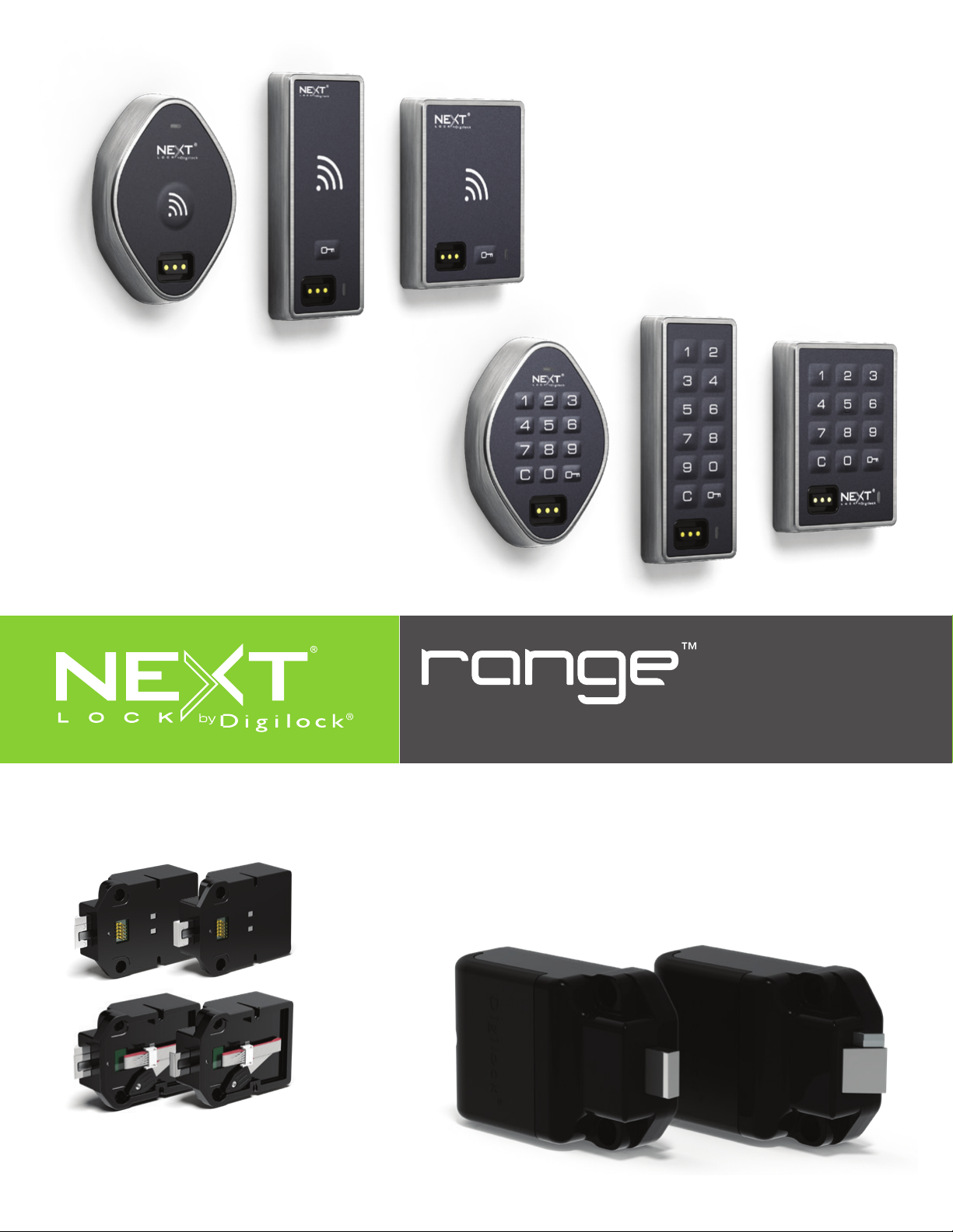
4G Rear Units (Latch and Bolt)
Installation Guide
Range Oval Front Unit (Keypad and RFID)
Range Narrow Front Unit (Keypad and RFID)
Range Standard Front Unit (Keypad and RFID)
Range Rear Unit (Latch and Bolt 5G)
Page 2

Table of Contents
Before Lock Installation..................................................................................................................................................................................................................................3
Surface Mount Installation
For door thickness measuring between .16” - .91” (4 mm - 23 mm)
Required Components ...............................................................................................................................................................................................................4
Installation
For door thickness measuring between .01" - .16" (0.2mm - 4 mm)
Required Components ...............................................................................................................................................................................................................7
Installation
Door Preparation
.........................................................................................................................................................................................................................................5
.........................................................................................................................................................................................................................................8
Strike Plate Installation
Required Components ............................................................................................................................................................................................................10
Installation
......................................................................................................................................................................................................................................11
Door Mounting Holes Drill Instructions and Template
Drill Instructions .........................................................................................................................................................................................................................12
Template for Standard & Vertical Body
Metal Door Preparation
Compatibility Guide
Removal of 3-hole Lock Plug
Removal of Padlock Hasp
.............................................................................................................................................................14
............................................................................................................................................14
..................................................................................................................................................15
......................................................................................................................................................................13
Page 3
3
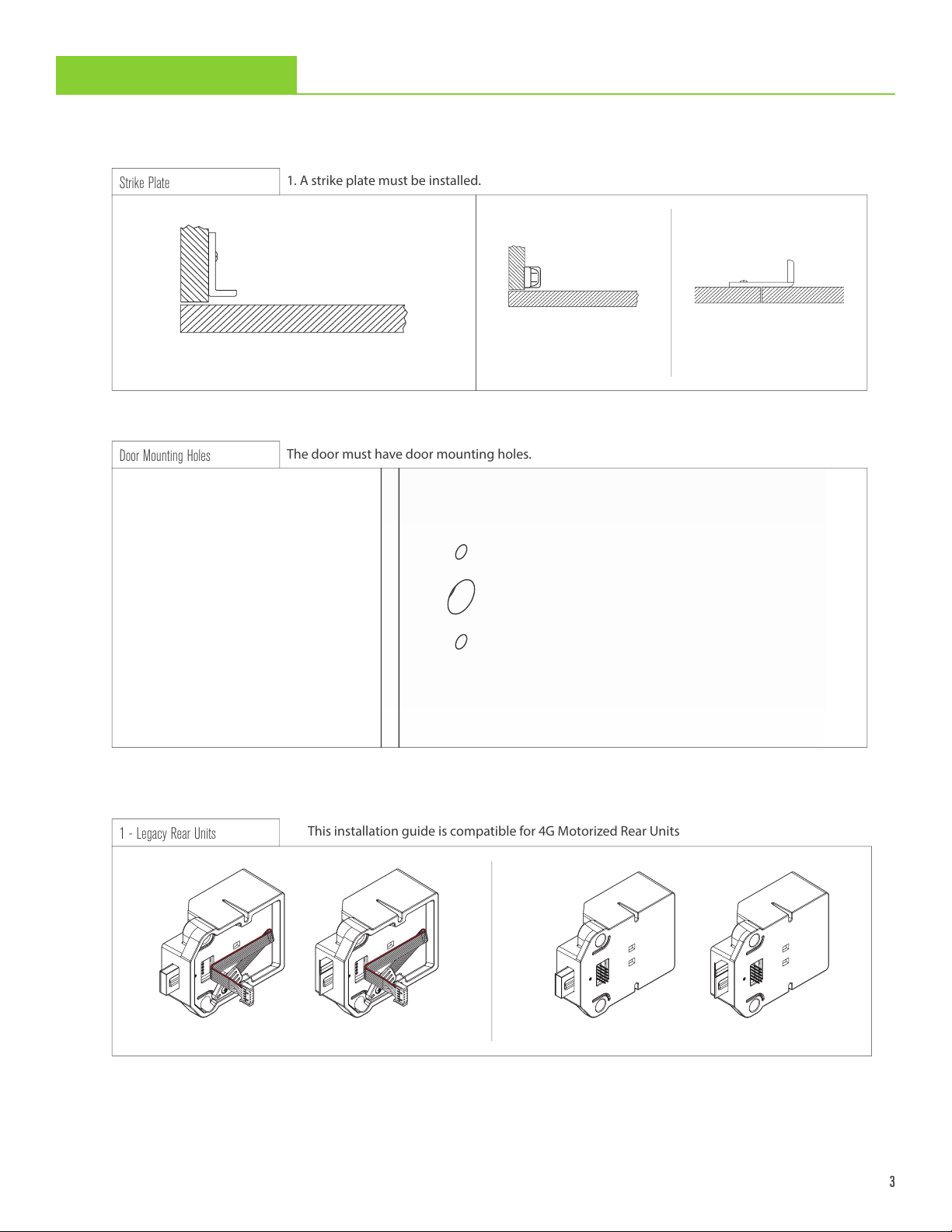
The door must have door mounting holes.
Door Mounting Holes
Before Lock Installation
1. A strike plate must be installed.
Strike Plate
1 - Legacy Rear Units
This installation guide is compatible for 4G Motorized Rear Units
The door must be prepared for lock installation.
1
Double Door Strike Plate
Angled Strike Plate
Security Strike Plate
Recommended for latch products
2
Deadbolt - Cable Deadlatch - Cable
Deadbolt - Cable Deadlatch - Cable
Page 4
4
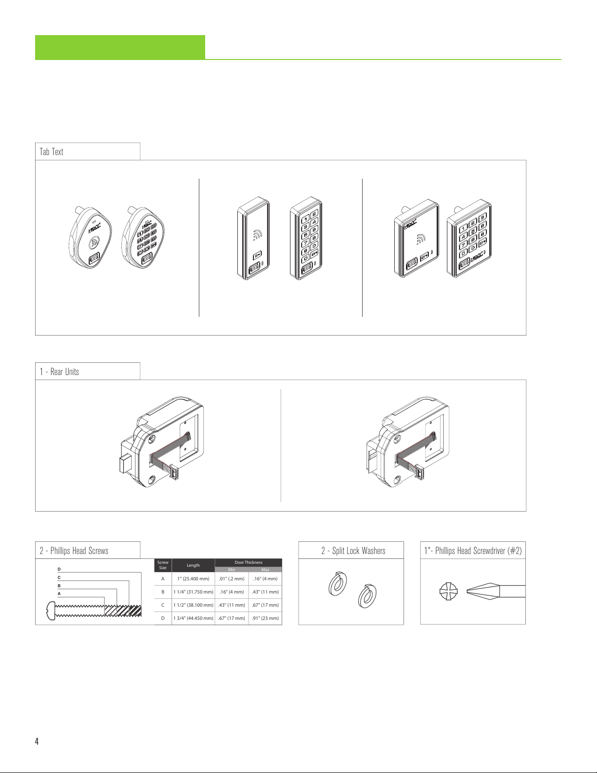
1*- Phillips Head Screwdriver (#2)
2 - Phillips Head Screws
D
C
B
A
Screw
Size
Length
Door Thickness
Min Max
A 1" (25.400 mm) .01" (.2 mm) .16" (4 mm)
B 1 1/4" (31.750 mm) .16" (4 mm) .43" (11 mm)
C 1 1/2" (38.100 mm) .43" (11 mm) .67" (17 mm)
D 1 3/4" (44.450 mm) .67" (17 mm) .91" (23 mm)
2 - Split Lock Washers
Surface Mount Installation
1 - Rear Units
Tab Text
For door thickness measuring between .16" - .91" (4 mm - 23 mm)
Required Components
Oval Body
RFID and Keypad
Narrow Body
RFID and Keypad
Standard Body
RFID and Keypad
Deadbolt - Cable Deadlatch - Cable
*Not included
Page 5
5
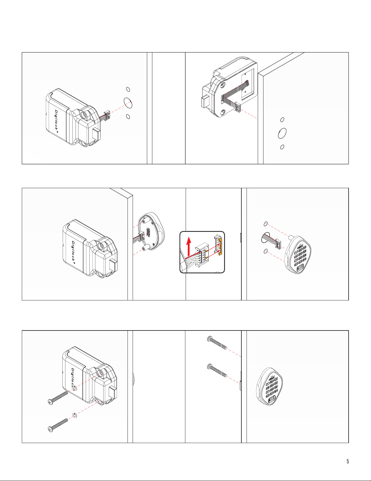
Installation
For illustration, a oval body keypad front unit with a bolt rear unit is used.
1
REAR VIEW FRONT VIEW
With the rear unit behind the door, extend the cable through the door’s mounting hole.
2
g.-1
REAR VIEW FRONT VIEW
Orient the cable with the red wire position on the top of the ribbon (see g-1). Attach the cable to the front unit using the corresponding
channel guides to ensure the snap connector is properly secured. Once connected a triple beep indicates successful connection.
3
REAR VIEW FRONT VIEW
Hold the front and rear units against the door and secure with the mounting screws. Ensure the remaining cable is not pinched.
Page 6

6
4
REAR VIEW FRONT VIEW
Test the lock while the door is open to ensure that the bolt or latch is operating properly.
For keypad locks with deadbolt rear units:
Press = ` to extend the bolt.
Press = ` again to retract the bolt.
For keypad locks with deadlatch rear units:
Press = ` to retract the latch.
The latch will extend automatically.
Repeat test with the door closed.
If ten rapid beeps are heard, the strike plate or door alignment may need adjustment to allow the lock to operate properly.
If the door does not lock when the bolt/latch is extended, the strike plate or lock position may need adjustment.
For touch RFID locks with deadbolt rear units:
Press RFID to extend the bolt.
Press RFID again to retract the bolt.
For touch RFID locks with deadlatch rear units:
Press RFID to retract the latch.
The latch will extend automatically.
Page 7

7
Surface Mount Installation
1* - 3/8” Nut Driver
2 - Locking Nuts
1 - Rear Units
Tab Text
For door thickness measuring between .01” - .16” (0.2 mm - 4 mm)
Required Components
Oval Body
RFID and Keypad
Narrow Body
RFID and Keypad
Deadbolt - Cable Deadlatch - Cable
Standard Body
RFID and Keypad
*Not included
Page 8

8
Installation
For illustration, a oval body keypad front unit with a bolt rear unit is used.
1
REAR VIEW FRONT VIEW
Insert the front unit screw posts through the door mounting holes.
2
REAR VIEW FRONT VIEW
Hold the front unit against the front of the door. Use the rear unit mounting holes as a guide, then slide the front and rear units together.
Make sure the connector pins align properly with the connector.
If properly connected, a triple beep will be heard and the LED will ash three times.
3
REAR VIEW FRONT VIEW
Insert the locking nuts on the screw posts and tighten using the ratchet/screw gun. Do not over tighten.
Page 9

9
4
REAR VIEW FRONT VIEW
Test the lock while the door is open to ensure that the bolt/latch is operating properly.
For keypad locks with deadbolt rear units:
Press = ` to extend the bolt.
Press = ` again to retract the bolt.
For keypad locks with deadlatch rear units:
Press = ` to retract the latch.
The latch will extend automatically.
Repeat test with the door closed.
If ten rapid beeps are heard, the strike plate or door alignment may need adjustment to allow the lock to operate properly.
If the door does not lock when the bolt/latch is extended, the strike plate or lock position may need adjustment.
For touch RFID locks with deadbolt rear units:
Press RFID to extend the bolt.
Press RFID again to retract the bolt.
For touch RFID locks with deadlatch rear units:
Press RFID to retract the latch.
The latch will extend automatically.
Page 10

10
1. A strike plate must be installed.
Strike Plate*
1*- Phillips Head Screwdriver (#1)
1*- Drill
1*- Pencil
1*- 1/6” Drill bit
Removable tape*
1*- 5/16” Drill bit
1*- Ruler
1*- 3/4” Drill bit
Door Preparation
Strike Plate Installation
Required Components
Angled Strike Plate
Security Strike Plate
Recommended for latch products
Double Door Strike Plate
*Not included
Page 11

11
Installation
Door Frame
0.32 in
(8 mm)
Mark Here
Door Frame
Drill Pilot
Holes Here
Door Frame
0.32 in
(8 mm)
Door Frame
0.32 in
(8 mm)
Mark Here
Door Frame
Door Frame
1
Position the strike plate on the door frame aligning it with
the center of the lock’s mounting holes.
3
2
Allow .32" (8 mm) from door edge and mark the position
of the adjustment slot holes.
4
Drill 0.25" (6.35 mm) pilot holes using a 1/6" drill bit.
5
Adjust the strike plate to the proper position (.32" (8 mm)
from the door edge) then tighten the self tapping screws.
Position the strike plate and the self tapping screws into the
adjustment slot holes. Do not tighten the screws.
6
Position and tighten the remaining self tapping screw
into the center hole.
Page 12

12
Door Mounting Holes Drill Instruction and Template
(a)
(b)
Strike Center
(b)
(a)
(a)
(b)
Drill x2
5/16” 0.3125 in
(7.94 mm)
Drill 3/4”
0.75 in (19.1 mm)
Drill Instructions
1
With the door open place the Template over the locker frame.
(a) Align the Edge of Strike Plate with the Strike Plate Marker.
(b) Center the Template to the center of the Strike Plate.
You may secure the Template with removable tape.
3
2
Close the door over the Template.
(a) Mark the door edge at the Template Center Line.
(b) Mark the Template with the edge of the door.
4
Place the Template on the front of the door.
(a) Align the drawn mark on the Template with the door edge.
(b) Center the Template with the mark on the door.
Secure the Template with removable tape.
Mark the center points of the door mounting holes on the front of
the door. Drill the holes according the specied dimensions.
Page 13

13
Template for Door Mounting Holes
Templates may not print to scale. Check all measurements before proceeding.
Before printing, turn o auto scaling in printer setup and print at 100%
All measurements in thousandths
ALIGN EDGE OF
STRIKE PLATE HERE
FOR LEFT
CLOSING DOOR
of an inch and millimeters
)mm( 9.72
001.1
.300
7.62 (mm)
use 5/16" bit
ALIGN EDGE OF
STRIKE PLATE HERE
FOR RIGHT
CLOSING DOOR
001.1
)mm( 9.72
CENTER LINE
CENTER LINE
ALIGN EDGE OF
STRIKE PLATE HERE
FOR LEFT
CLOSING DOOR
)mm( 9.72
001.1
.905
23 (mm)
.750
19.05 (mm)
use 3/4" bit
.300
7.62 (mm)
.905
23 (mm)
001.1
)mm(9.72
ALIGN EDGE OF
STRIKE PLATE HERE
FOR RIGHT
CLOSING DOOR
Page 14

14
Metal Door Preparation
Single Point Latch
Handle
Standard Lift
Box Locker Padlock Hasp
Compatibility Guide
Digilock is compatible with a majority of 3-hole conguration, latch, and handle door types. Some doors may require modication to clear
obstructions.
Removal of 3-hole Lock Plug
Remove any obstructions to the door mounting holes.
1 2
Rear View of Locker Door with Lock Plug
Page 15

15
Removal of Padlock Hasp
1* - Handheld Grinder or Hack Saw
1* - Metal File
The padlock hasp must be removed
*Not included
1
Close the door and make sure that nothing is
protruding above the surface of the door.
3
2
Close the door and mark the area to cut the
padlock hasp.
4
Open the door then cut the padlock hasp on
the marked cut-line.
Smooth out rough or sharp edges.
Page 16

IG-NL-R-DEN
010919 707 766 6000 | sales@digilock.com | www.digilock.com
 Loading...