

Page 1
Page 2

3$57180%(5
6758&785(
Page 3
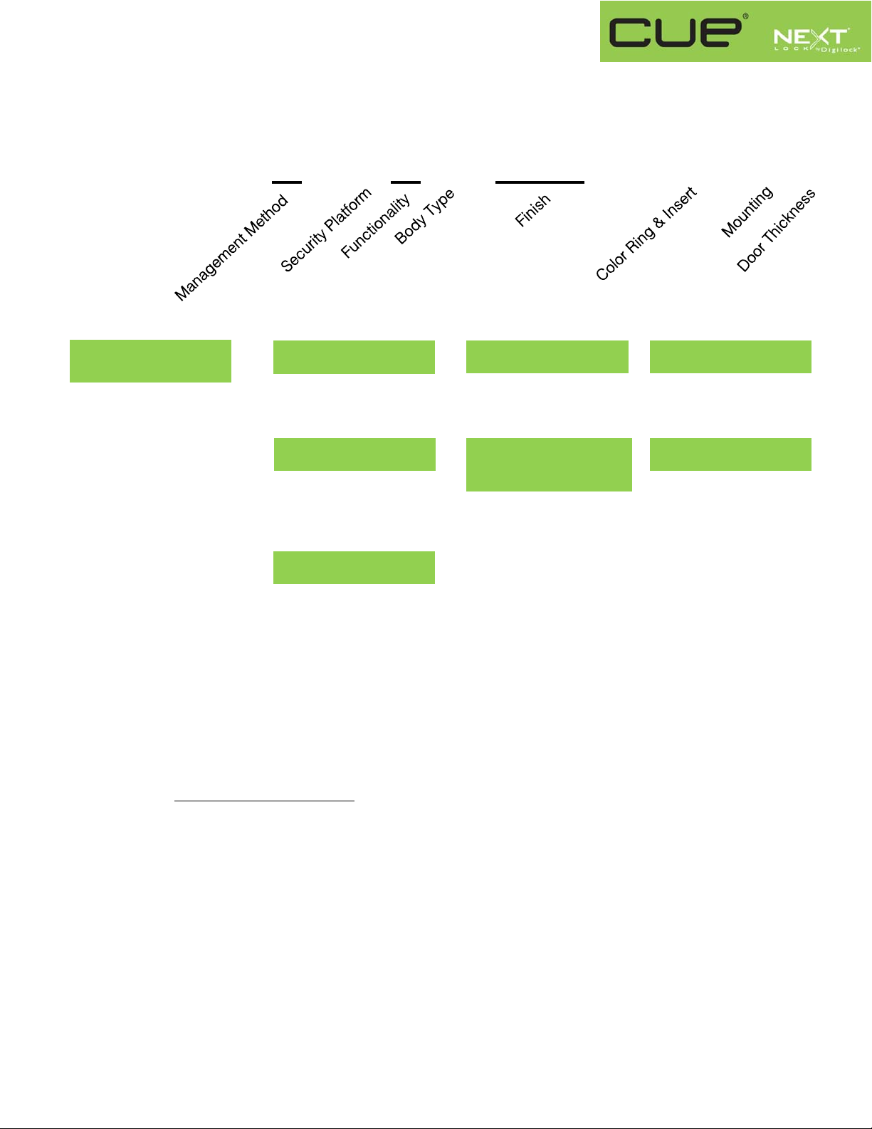
NXT – UKX – AXS –XXX – 01 – 2U
Management Method
C = Code Managed
K = Key Managed
Interface S
Example:
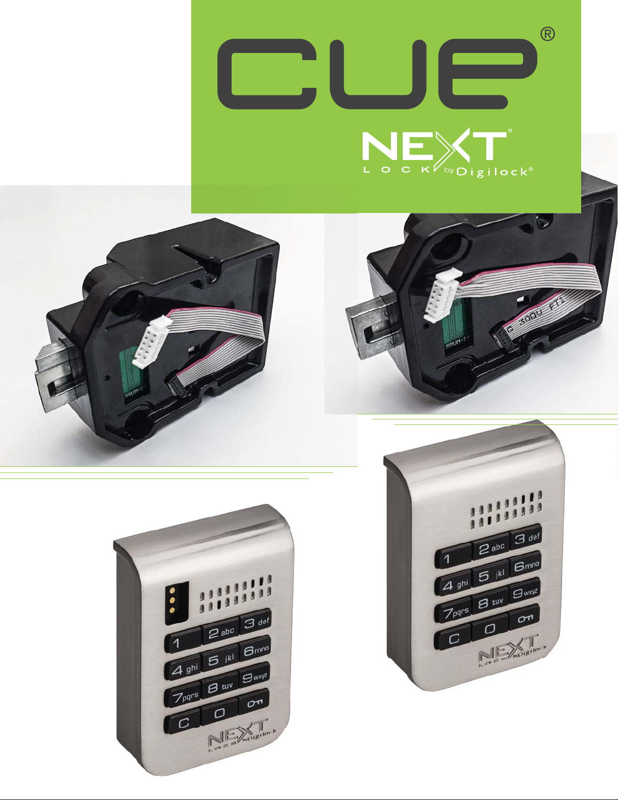
NXT-UKC-ADS-619-01-2U
NEXTLOCK CUE, keypad, code managed, advanced security, dual function preset to shared use, standard
body, brushed nickel, black insert, surface mount on a door thickness up to .91” (23mm)
Security Platform
A = Advanced
Functionality
D Dual (Default shared)
P Assigned
Body Type
S = Standard
Finish
619 = Brushed Nickel
605 = Polished Brass
Color Ring
& Insert
1 = Black
Mounting
2 = Surface
Door Thickness
U = up to .91” (23 mm)
Effective 6/17/2015
Page 4

352'8&7*8,'(
Page 5

Product Guide
Key Managed
Bolt Mechanism
CUE is a keypad lock designed to operate for shared or assigned use applications. In shared use functionality, the user chooses any
available locker and enters a self-selected 4-digit code to lock and the same code to later unlock. Once unlocked, the locker is available
for a different user. In assigned use functionality, the user is assigned a specific locker and a 4-digit code or User Key to operate the
lock. A Programming Key unique to the lock system programs up to 25 Manager Keys to the locks for management access, external
power, and inspection.
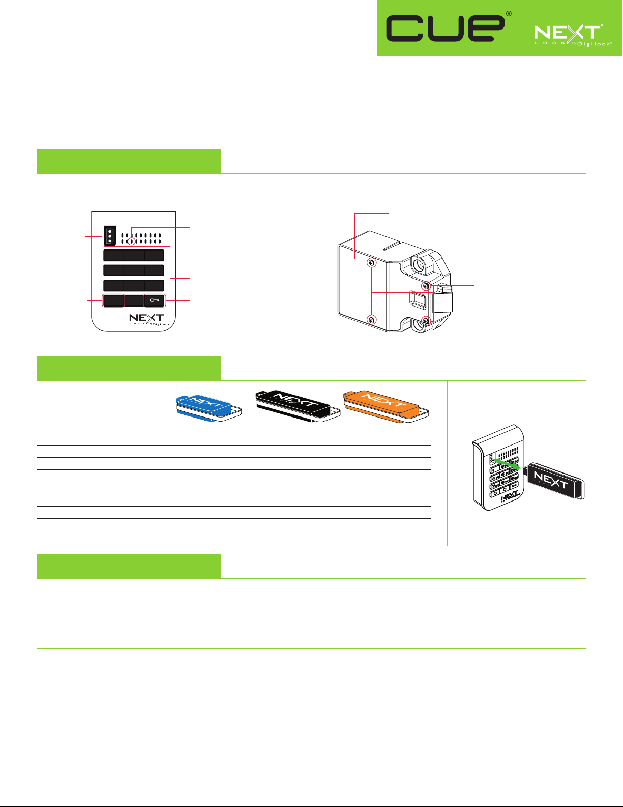
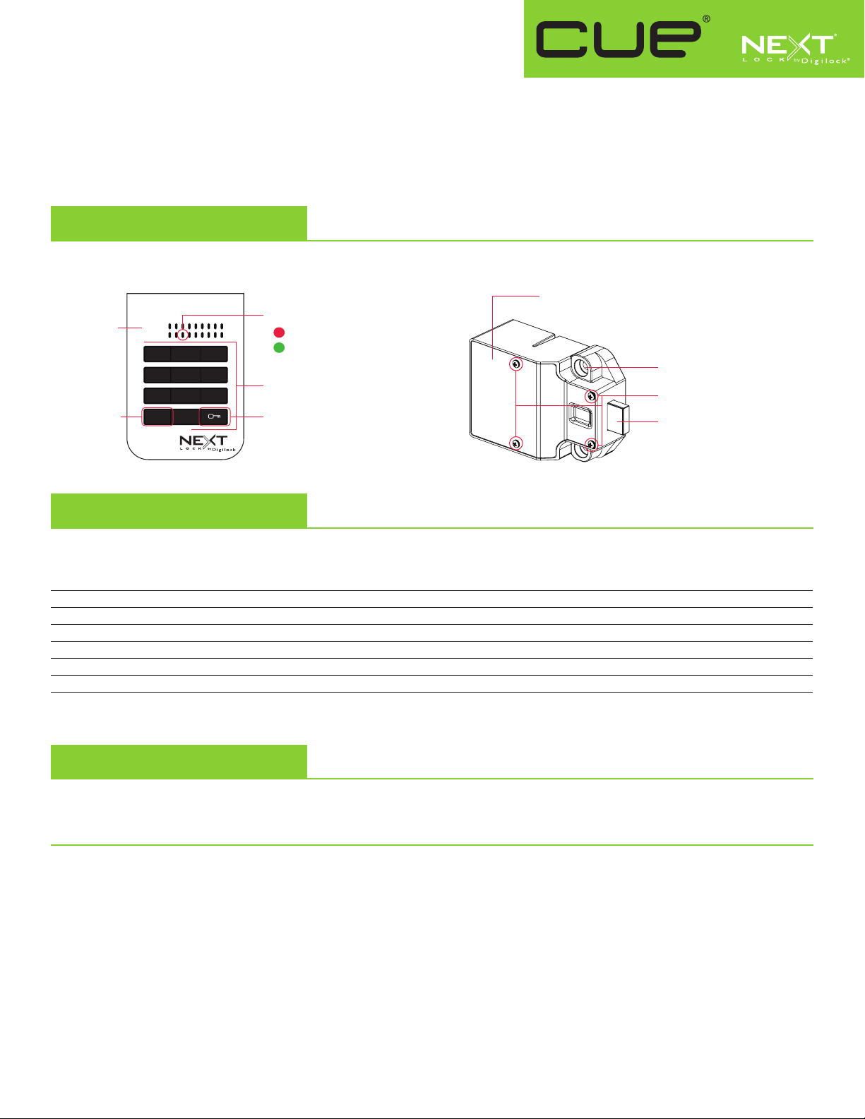
Lock Parts
Front Unit
Key Slot
1 2 3
4 5 6
7 8 9
C Button Key Button
C 0
LED Usage Indicator
Shared Use
Assigned Use
Alpha Numeric
Keypad
Rear Unit
Keys
User Key Manager Key* Programming Key**
Operates the lock
Overrides user access
Allows management inspection
Provides external power
Registers Manager Keys
Assigns user credential (in assigned use)
Sets lock functionality
*Up to 25 Manager Keys may be registered to each lock **1 Programming Key allowed per lock group.
• • •
• •
• •
• •
•
Cover Plate
Lock Mounting Holes
Cover Plate Screws
1/2" (12.7 mm) Deadbolt
Key Insertion
•
Next logo must face left.
•
Initial Setup
New locks operate only by pressing = `. Locks must be setup to allow full operation.
a. Touch the Programming Key to the key slot until a two-tone beep is heard and the LED turns on.
b. Touch each Manager Key to the key slot. A two-tone beep will be heard for each Manager Key that is successfully registered.
c. Touch the Programming Key to the key slot until a two-tone beep is heard and the LED turns off.
d. Repeat above steps for each lock or follow Express Register Manager Key(s) instructions to setup all locks.
Express Register Manager Key(s)
The Programming Key can quickly register the same Manager Key(s) to operate multiple locks.
a. Go to the lock registered with the Manager Key(s).
b. Press =`66`. The LED will turn on.
c. Touch the Programming Key to the key slot until a two-tone beep is heard and the LED turns off.
d. At each lock to be registered, touch the Programming Key to the key slot until a two-tone beep is heard and the LED flashes once to
indicate successful registration.
e. End express registration,* go to any registered lock and press =` then touch the Programming Key to the key slot to operate the lock.
* The Programming Key will continue to function in express registration mode until it is used to operate a lock.
Page 6

Product Guide
Key Managed
Bolt Mechanism
Programming Instructions
Register/Add Manager Key(s)
Manager Key(s) can be registered to a lock after Initial Setup has been completed.
a. Go to the lock requiring Manager Key(s).
b. Press =` 55 `. The LED will turn on.
c. Touch the Programming Key to the key slot until a two-tone beep is heard.
d. Touch each Manager Key to the key slot. A two-tone beep will be heard for each Manager Key that is successfully registered.
e. Touch the Programming Key to the key slot until a two-tone beep is heard and the LED turns off.
f. Repeat above steps for each lock or follow Express Register Manager Key(s) instructions to register the same Manager Key(s)
to multiple locks.
For Lost or Stolen Keys
For a lost or stolen Programming Key:
A replacement Programming Key must be purchased and registered to the lock(s) to prevent the lost/stolen Programming Key from
accessing/programming a lock.
For lost or stolen Manager Key(s):
All registered Manager Keys must be erased and only the remaining Manager Keys must be registered to the lock(s) to prevent the lost/
stolen Manager Key from accessing a lock. Purchase additional Manager Key(s) from an authorized distributor.
a. Collect all remaining Manager Key(s).
b. Press
c. Touch the Programming Key to the key slot until a two-tone beep is heard.
d. Touch the Programming Key to the key slot again until three sets of two-tone beeps are heard and the LED turns off. All previously
e. Follow Register/Add Manager Key(s) instructions to register the remaining Manager Key(s).
=`55`
registered Manager Key(s) are erased from the lock.
. The LED will turn on.
Set Lock Functionality
Each lock can be set for either shared or assigned use functionality. The default functionality is shared use. Press = to check functionality.
If in shared use, LED is red. If in assigned use, LED is green.
Set lock for assigned use functionality:
a. Press =` 65 `. The LED will turn on.
b. Touch the Programming Key to the key slot until a two tone beep is heard and the LED turns off.
c. Follow Assign User Credential instructions to assign a User Code or User Key to operate the lock.
Set lock for shared use functionality:
a. Press =` 56 `. The LED will turn on.
b. Touch the Programming Key to the key slot until a two tone beep is heard and the LED flashes once.
Auto Unlock (for shared use functionality only)
When in shared use functionality, each lock can be programmed to auto unlock after a set number of hours. The default setting is OFF
(does not auto unlock).
To turn on Auto Unlock:
a. Press =` 95 ` then touch the Programming Key to the key slot until the LED turns on.
b. Set the number of hours: Press 1 - 99 `. Two sets of two-tone beeps will be heard and the LED will turn off.
For example: Press 4 ` to set the lock to auto unlock after 4 hours.
To turn off Auto Unlock:
a. Press =` 94 `. The LED will start to flash.
b. Touch the Programming Key to the key slot until a two tone beep is heard and the LED turns off.
Page 7

Product Guide
Key Managed
Bolt Mechanism
LED Usage Indicator (for shared use functionality only)
When in shared use functionality, each lock can be programmed to have the LED flash or not flash while the lock is in use. The default
setting is ON (red LED flashes while lock is in use).
To turn off the LED Usage Indicator:
a. Press =` 92 `. The LED will start to flash.
b. Touch the Programming Key to the key slot until a two-tone beep is heard and the LED turns off.
To turn on the LED Usage Indicator:
a. Press =` 91 `. The LED will start to flash.
b. Touch the Programming Key to the key slot until a two-tone beep is heard and the LED turns off.
Assign User Credential (for assigned use functionality only)
Make sure that the lock is set for assigned use functionality. Once a user credential is assigned, the previously assigned user credential will
no longer operate the lock.
Assign a User Code (default user code = 1234):
a. Press =` then touch a registered Manager Key to the key slot until the LED turns on.
b. Press = [new 4-digit code] `. A two-tone beep will be heard.
c. To confirm, press = [the same 4-digit code] `. Two sets of two-tone beeps will be heard and the LED will turn off.
Assign a User Key:
a. Press =` then touch a registered Manager Key to the key slot until the LED turns on.
b. Touch a User Key to the key slot until a two-tone beep is heard and the LED turns off.
Operating Instructions
Operate with a User Code
For assigned use functionality:
▪▪ To▪unlock:▪Press▪= [assigned▪4-digit▪code] `*.
▪▪ To▪relock:▪Press▪=``.
For shared use functionality:
▪▪ To▪lock:▪Press▪= [any▪4-digit▪code] `.
▪▪ To▪unlock:▪Press▪= [the▪same▪4-digit▪code] `*.
Operate with a User Key
For assigned use functionality:
▪▪ To▪unlock:▪Touch▪the▪assigned▪User▪Key▪to▪the▪key▪slot.
▪▪ To▪relock:▪Touch▪the▪assigned▪User▪Key▪to▪the▪key▪slot.
For shared use functionality:
▪▪ To▪lock:▪Touch▪any▪User▪Key▪to▪the▪key▪slot.
▪▪ To▪unlock:▪Touch▪the▪same▪User▪Key▪to▪the▪key▪slot.
Operate with a Registered Manager Key
▪▪ To▪unlock▪and▪lock:▪Touch▪a▪registered▪Manager▪Key.**
Operate with a Registered Programming Key
▪▪ To▪unlock▪and▪lock:▪Press▪=`▪then▪touch▪the▪Programming▪Key▪to▪the▪key▪slot.**
* The lock will go into “Sleep Mode” (keypad is disabled) after 3 consecutive incorrect user code entries.
** If a registered Manager Key or the Programming Key is used to unlock and then relock, the previous user credential will continue to operate the lock.
Page 8

Product Guide
Key Managed
Bolt Mechanism
Support
Sleep Mode
After▪three▪consecutive▪incorrect▪User▪Code▪entries▪to▪unlock,▪the▪lock▪will▪go▪into▪“Sleep▪Mode”▪for▪one▪minute▪and▪
for▪an▪additional▪minute▪for▪each▪subsequent▪incorrect▪entry.▪The▪keypad▪is▪disabled▪while▪in▪“Sleep▪Mode”.
Error Condition Indicator
10 rapid beeps:
The▪lock▪is▪binding▪which▪means▪that▪either▪door▪alignment▪or▪items▪in▪the▪locker▪are▪preventing▪the▪lock▪from▪operating.▪
Press▪on▪the▪door▪while▪operating▪the▪lock.▪If▪error▪condition▪persists,▪contact▪Digilock▪support▪for▪assistance.
2 sets of three beeps:
The▪batteries▪are▪low.▪Replace▪the▪batteries.
1 beep:
The▪lock▪does▪not▪recognize▪the▪User▪Code,▪User▪Key,▪Programming▪Key,▪or▪Manager▪Key.
Does not Unlock with the User Code or User Key
The▪lock▪does▪not▪recognize▪the▪User▪Code▪or▪User▪Key.▪For▪immediate▪access,▪operate▪with▪a▪registered▪Manager▪Key.▪If▪in▪
assigned▪use▪functionality,▪follow▪Assign▪User▪Credential▪instructions▪to▪assign▪a▪new▪User▪Code▪or▪User▪Key▪to▪the▪lock.
Does not operate with a Manager Key
The▪lock▪does▪not▪recognize▪the▪Manager▪Key.▪Follow▪Register/Add▪Manager▪Key(s)▪instructions▪to▪register▪the▪Manager▪
Key▪to▪the▪lock.▪For▪immediate▪access,▪operate▪with▪another▪registered▪Manager▪Key▪or▪with▪the▪Programming▪Key.
Does not operate with the Programming Key
The▪lock▪does▪not▪recognize▪the▪Programming▪Key.▪Contact▪Digilock▪support.
No Audible Feedback when = is Pressed
▪ The lock may be in “Sleep Mode”. For immediate access, operate with a registered Manager Key.
▪ The batteries may need to be replaced. Operate with the Manager Key to unlock then replace the batteries.
▪ The front unit may not be properly connected to the rear unit. Remove the lock from the door and check the cable connection.
▪ If error condition persists, contact Digilock support.
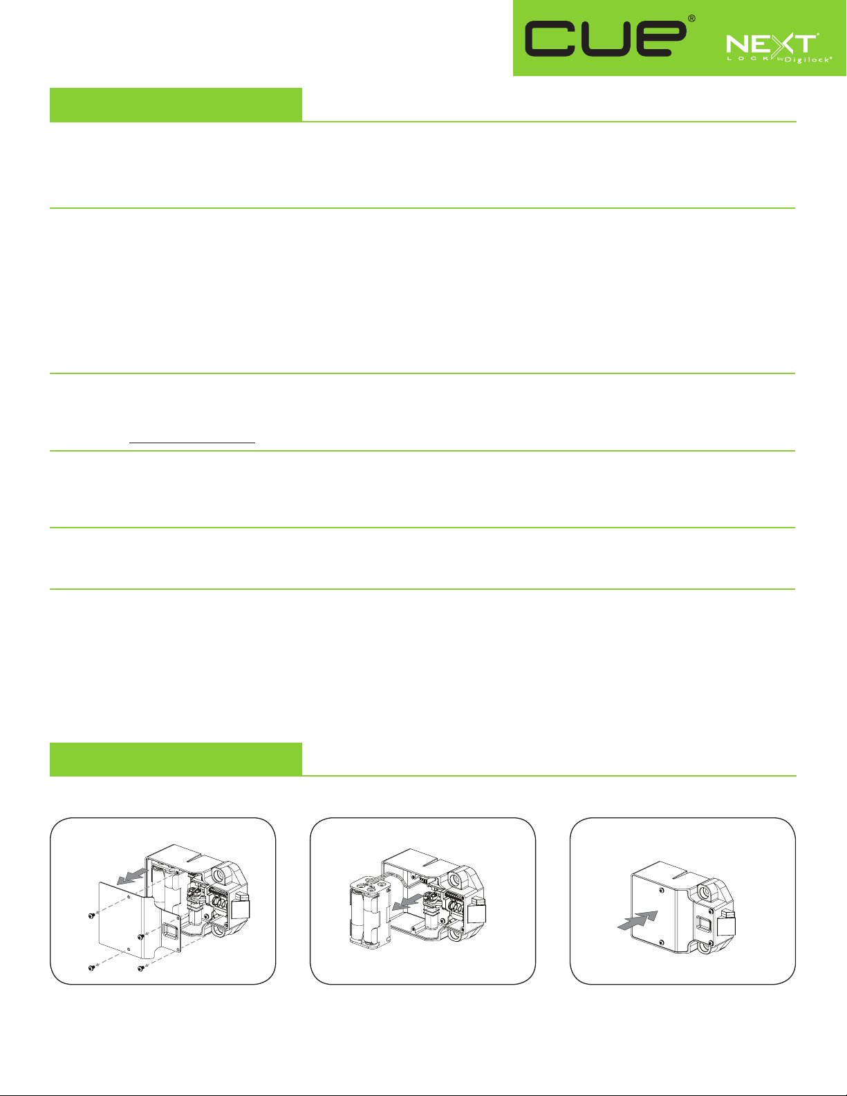
Battery Replacement
It is not necessary to uninstall the lock from the door.
1 2 3
Remove the screws and the cover plate. Pull the battery pack from the rear
housing. Replace with four premium
alkaline AA batteries.
121615
PG-NXT-UKK-ADS-DEN
Place the battery pack back into the rear
housing and screw cover plate in place.
Phone: 707 766 6000
www.digilock.com | sales@digilock.com
Page 9
Product Guide
Key Managed
Latch Mechanism
CUE keypad locks with a deadlatch are designed to operate for assigned use applications. In assigned use functionality, the user is
assigned a specific locker and a 4-digit code or User Key to operate the lock. A Programming Key unique to the lock system programs
up to 25 Manager Keys to the locks for management access, external power, and inspection.
Lock Parts
Front Unit
Key Slot
1 2 3
4 5 6
7 8 9
C Button Key Button
C 0
LED Usage Indicator
Alpha Numeric
Keypad
Rear Unit
Keys
User Key Manager Key* Programming Key**
Operates the lock
Overrides user access
Allows management inspection
Provides external power
Registers Manager Keys
Assigns user credential
*Up to 25 Manager Keys may be registered to each lock **1 Programming Key allowed per lock group.
• • •
• •
• •
• •
•
Cover Plate
Lock Mounting Holes
Cover Plate Screws
1/2" (12.7 mm) Deadlatch
Key Insertion
•
Next logo must face left.
Initial Setup
New locks operate with =`. Locks must be setup to allow full operation.
a. Touch the Programming Key to the key slot until a two-tone beep is heard and the LED turns on.
b. Touch each Manager Key to the key slot. A two-tone beep will be heard for each Manager Key that is successfully registered.
c. Touch the Programming Key to the key slot until a two-tone beep is heard and the LED turns off.
d. Repeat above steps for each lock or follow Express Register Manager Key(s) instructions to setup all locks.
Express Register Manager Key(s)
The Programming Key can quickly register the same Manager Key(s) to operate multiple locks.
a. Go to the lock registered with the Manager Key(s).
b. Press =`66`. The LED will turn on.
c. Touch the Programming Key to the key slot until a two-tone beep is heard and the LED turns off.
d. At each lock to be registered, touch the Programming Key to the key slot until a two-tone beep is heard and the LED flashes once to
indicate successful registration.
e. End express registration,* go to any registered lock and press =` then touch the Programming Key to the key slot to operate the lock.
* The Programming Key will continue to function in express registration mode until it is used to operate a lock.
Page 10

Product Guide
Key Managed
Latch Mechanism
Programming Instructions
Register/Add Manager Key(s)
Manager Key(s) can be registered to a lock after Initial Setup has been completed.
a. Go to the lock requiring Manager Key(s).
b. Press =`55`. The LED will turn on.
c. Touch the Programming Key to the key slot until a two-tone beep is heard.
d. Touch each Manager Key to the key slot. A two-tone beep will be heard for each Manager Key that is successfully registered.
e. Touch the Programming Key to the key slot until a two-tone beep is heard and the LED turns off.
f. Repeat above steps for each lock or follow Express Register Manager Key(s) instructions to register the same Manager Key(s)
to multiple locks.
For Lost or Stolen Keys
For a lost or stolen Programming Key:
A replacement Programming Key must be purchased and registered to the lock(s) to prevent the lost/stolen Programming Key from accessing/
programming a lock.
For lost or stolen Manager Key(s):
All registered Manager Keys must be erased and only the remaining Manager Keys must be registered to the lock(s) to prevent the lost/stolen
Manager Key from accessing a lock. Purchase additional Manager Key(s) from an authorized distributor.
a. Collect all remaining Manager Key(s).
b. Press =`55`. The LED will turn on.
c. Touch the Programming Key to the key slot until a two-tone beep is heard.
d. Touch the Programming Key to the key slot again until three sets of two-tone beeps are heard and the LED turns off.
All previously registered Manager Key(s) are erased from the lock.
e. Follow Register/Add Manager Key(s) instructions to register the remaining Manager Key(s).
Assign User Credential
Once a user credential is assigned, the previously assigned user credential will no longer operate the lock.
Assign a User Code (default user code = 1234):
a. Press =` then touch a registered Manager Key to the key slot until the LED turns on.
b. Press = [new 4-digit code] `. A two-tone beep will be heard.
c. To confirm, press = [the same 4-digit code] `. Two sets of two-tone beeps will be heard and the LED will turn off.
Assign a User Key:
a. Press =` then touch a registered Manager Key to the key slot until the LED turns on.
b. Touch a User Key to the key slot until a two-tone beep is heard and the LED turns off.
Page 11
Product Guide
Key Managed
Latch Mechanism
Operating Instructions
Operate with an assigned User Code
▪ To unlock: Press = [assigned 4-digit code] `*.
▪ To relock: Close the door.
Operate with an assigned User Key
▪ To unlock: Touch the assigned User Key to the key slot.
▪ To relock: Close the door.
Operate with a Registered Manager Key
▪ To unlock: Touch a registered Manager Key.
▪ To relock: Close the door.
Operate with a Registered Programming Key
▪ To unlock: Press =` then touch the Programming Key to the key slot.
▪ To relock: Close the door.
* The lock will go into “Sleep Mode” (keypad is disabled) after 3 consecutive incorrect user code entries.
Page 12
Product Guide
Key Managed
Latch Mechanism
Support
Sleep Mode
After three consecutive incorrect User Code entries to unlock, the lock will go into “Sleep Mode” for one minute and
for an additional minute for each subsequent incorrect entry. The keypad is disabled while in “Sleep Mode”.
Error Condition Indicator
10 rapid beeps:
The lock is binding which means that either door alignment or items in the locker are preventing the lock from operating.
Press on the door while operating the lock. If error condition persists, contact Digilock support for assistance.
2 sets of three beeps:
The batteries are low. Replace the batteries.
1 beep:
The lock does not recognize the User Code, User Key, Programming Key, or Manager Key.
Does not Unlock with the User Code or User Key
The lock does not recognize the User Code or User Key. For immediate access, operate with a registered Manager
Key. Follow Assign User Credential instructions to assign a new User Code or User Key to the lock.
Does not operate with a Manager Key
The lock does not recognize the Manager Key. Follow Register/Add Manager Key(s) instructions to register the Manager
Key to the lock. For immediate access, operate with another registered Manager Key or with the Programming Key.
Does not operate with the Programming Key
The lock does not recognize the Programming Key. Contact Digilock support.
No Audible Feedback when = is Pressed
▪ The lock may be in “Sleep Mode”. For immediate access, operate with a registered Manager Key.
▪ The batteries may need to be replaced. Operate with the Manager Key to unlock then replace the batteries.
▪ The front unit may not be properly connected to the rear unit. Remove the lock from the door and check the cable connection.
▪ If error condition persists, contact Digilock support.
Battery Replacement
It is not necessary to uninstall the lock from the door.
1 2 3
Remove the screws and the cover plate. Pull the battery pack from the rear
housing. Replace with four premium
alkaline AA batteries.
121615
PG-NXT-UKK-APS-DEN
Place the battery pack back into the rear
housing and screw cover plate in place.
Phone: 707 766 6000
www.digilock.com | sales@digilock.com
Page 13
Product Guide
Code Managed
Bolt Mechanism
CUE is a keypad lock designed to operate for shared or assigned use applications. In shared use functionality, the user chooses any
available locker and enters a self-selected 4-digit code to lock and the same code to later unlock. Once unlocked, the locker is available
for a different user. In assigned use functionality, the user is assigned a specific locker and a 4-digit code to operate the lock. Owner and
Manager Codes provide management access and inspection.
Lock Parts
Front Unit
Key Slot
1 2 3
4 5 6
7 8 9
C Button Key Button
C 0
Codes
Operates the lock
Overrides user access
Allows management inspection
Programs Manager Code
Programs Owner Code
Assigns User Code
Sets lock functionality
LED Usage Indicator
Shared Use
Assigned Use
Alpha Numeric
Keypad
Rear Unit
Cover Plate
Lock Mounting Holes
Cover Plate Screws
1/2" (12.7 mm) Deadbolt
____ _____ ______
4-digit
User Code
• • •
5-digit
Manager Code
• •
• •
• •
•
6-digit
Owner Code
•
•
Default Settings
New locks operate with the default Owner and Manager Codes. A new Owner and Manager Code must be programmed on the lock to
prevent the default codes from operating the lock.
Functionality = Shared Use Owner Code = 1 2 3 4 5 6 Manager Code = 1 2 3 4 5
Page 14

Product Guide
Code Managed
Bolt Mechanism
Programming Instructions
Program a New 6-digit Owner Code
The Owner Code can only be programmed by using the current Owner Code.
a. Press =` [current Owner Code] `. A two-tone beep will be heard and the LED will turn on.
b. Press = [new Owner Code] `. A two-tone beep will be heard.
c. To confirm, press = [the same new Owner Code] `. Two sets of two-tone beeps will be heard and the LED will turn off.
Program a New 5-digit Manager Code
To Program the Manager Code by using the Owner Code:
a. Press =` [Owner Code] `. A two-tone beep will be heard and the LED will turn on.
b. Press = [new Manager Code] `. A two-tone beep will be heard.
c. To confirm, press = [the same new Manager Code] `. Two sets of two-tone beeps will be heard and the LED will turn off.
To Program the Manager Code by using the current Manager Code
a. Press =` [current Manager Code] `. A two-tone beep will be heard and the LED will turn on.
b. Press = [new Manager Code] `. A two-tone beep will be heard.
c. To confirm, press = [the same new Manager Code] `. Two sets of two-tone beeps will be heard and the LED will turn off.
:
Set Lock Functionality
Each lock can be set for either shared or assigned use functionality. The default functionality is shared use. Press = to check functionality.
If in shared use, LED is red. If in assigned use, LED is green.
Set lock for assigned use functionality:
a. Press =` [Owner Code] `. The LED will turn on.
b. Press = 65 `. Two sets of two-tone beeps will be heard and the LED will flash twice.
c. Follow Assign User Code instructions to assign a User Code to operate the lock.
Set lock for shared use functionality
a. Press =` [Owner Code] `. The LED will turn on.
b. Press = 56 `. Two sets of two-tone beeps will be heard and the LED will flash twice.
:
Auto Unlock (for shared use functionality only)
When in shared use functionality, each lock can be programmed to auto unlock after a set number of hours. The default setting is OFF
(does not auto unlock).
To turn on Auto Unlock:
a. Press =` [Owner Code] `. A two-tone beep will be heard and the LED will turn on.
b. Press = 95 `. A two-tone beep will be heard.
c. Set the number of hours: Press 1 - 99 `. Two sets of two-tone beeps will be heard and the LED will turn off.
For example: Press 4 ` to set the lock to auto unlock after 4 hours.
To turn off Auto Unlock:
a. Press =` [Owner Code] `. A two-tone beep will be heard and the LED will turn on.
b. Press = 94 `. Two sets of two-tone beeps will be heard and the LED will turn off.
LED Usage Indicator (for shared use functionality only)
When in shared use functionality, each lock can be programmed to have the LED flash or not flash while the lock is in use. The default
setting is ON (red LED flashes while lock is in use).
To turn off the LED Usage Indicator:
a. Press =` [Owner Code] `. A two-tone beep will be heard and the LED will turn on.
b. Press = 92 `. A two-tone beep will be heard and the LED will turn-off.
To turn on the LED Usage Indicator:
a. Press =` [Owner Code] `. A two-tone beep will be heard and the LED will turn on.
b. Press = 91 `. A two-tone beep will be heard and the LED will turn-off
Page 15

Product Guide
Code Managed
Bolt Mechanism
Assign User Code (for assigned use functionality only)
Make sure that the lock is set for assigned use functionality. Once a User Code is assigned, the previously assigned User Code will no
longer operate the lock.
Assign a User Code (default User Code = 1234):
a. Press =` [Manager Code] `. A two-tone beep will be heard and the LED will turn on.
b. Press = [new User Code] `. A two-tone beep will be heard.
c. To confirm, press = [the same new User Code] `. Two sets of two-tone beeps will be heard and the LED will turn off.
Operating Instructions
Operate with a User Code
For assigned use functionality:
▪ To unlock: Press = [assigned 4-digit code] `*.
▪ To relock: Press =``.
For shared use functionality:
▪ To lock: Press = [any 4-digit code] `.
▪ To unlock: Press = [the same 4-digit code] `*.
Operate with a Registered Manager Code
▪ To lock and unlock: Press = [Manager Code]
`**
.
Operate with a Registered Owner Code
▪ To lock and unlock: Press = [Owner Code]
* The lock will go into “Sleep Mode” (keypad is disabled for 1 minute) after 3 consecutive incorrect entries.
** If the Owner Code or Manager Code is used to unlock and then relock, the previous User Code will continue to operate the lock.
`**
.
Page 16

Product Guide
Code Managed
Bolt Mechanism
Support
Sleep Mode
After three consecutive incorrect User Code entries to unlock, the lock will go into “Sleep Mode” for one minute and
for an additional minute for each subsequent incorrect entry. The keypad is disabled while in “Sleep Mode”.
Error Condition Indicator
10 rapid beeps:
The lock is binding which means that either door alignment or items in the locker are preventing the lock from operating.
Press on the door while operating the lock. If error condition persists, contact Digilock support for assistance.
2 sets of three beeps:
The batteries are low. Replace the batteries.
1 beep:
The lock does not recognize the User Code, Manager Code, or Owner Code.
Does not Unlock with the User Code
The lock does not recognize the User Code. For access, operate with the Manager Code. If in assigned use functionality, follow
Assign User Code instructions to assign a new User Code to the lock.
Does not operate with a Manager Code
The lock does not recognize the Manager Code. Follow instructions to Program a New Manager Code by using the Owner Code. For
access, operate with the Owner Code.
Does not operate with the Owner Code
The lock does not recognize the Owner Code. Contact Digilock support.
No Audible Feedback when = is Pressed
▪ The lock may be in “Sleep Mode”. The keypad is disabled for one minute while in sleep mode.
▪ The batteries may need to be replaced.
▪ The front unit may not be properly connected to the rear unit. Remove the lock from the door and check the cable connection.
▪ If error condition persists, contact Digilock support.
Battery Replacement
It is not necessary to uninstall the lock from the door.
1 2 3
Remove the screws and the cover plate. Pull the battery pack from the rear
housing. Replace with four premium
alkaline AA batteries.
121615
PG-NXT-UKC-ADS-DEN
Place the battery pack back into the rear
housing and screw cover plate in place.
Phone: 707 766 6000
www.digilock.com | sales@digilock.com
Page 17

Product Guide
Code Managed
Latch Mechanism
CUE is a keypad lock designed to operate for assigned use applications. In assigned use functionality, the user is assigned a specific
locker and a 4-digit code to operate the lock. Owner and Manager Codes provide management access and inspection.
Lock Parts
Front Unit
1 2 3
4 5 6
7 8 9
C Button Key Button
C 0
Codes
Operates the lock
Overrides user access
Allows management inspection
Programs Manager Code
Programs Owner Code
Assigns User Code
LED Usage Indicator
Alpha Numeric
Keypad
Rear Unit
Cover Plate
Lock Mounting Holes
Cover Plate Screws
1/2" (12.7 mm) Deadlatch
____ _____ ______
4-digit
User Code
• • •
5-digit
Manager Code
• •
• •
• •
•
6-digit
Owner Code
•
Default Settings
New locks operate with the default Owner and Manager Codes. A new Owner and Manager Code must be programmed on the lock to
prevent the default codes from operating the lock.
Functionality = Assigned Use
Owner Code
= 1 2 3 4 5 6 Manager Code = 1 2 3 4 5 User Code = 1 2 3 4
Page 18

Product Guide
Code Managed
Latch Mechanism
Programming Instructions
Program a New 6-digit Owner Code
The Owner Code can only be programmed by using the current Owner Code.
a. Press =` [current Owner Code] `. A two-tone beep will be heard and the LED will turn on.
b. Press = [new Owner Code] `. A two-tone beep will be heard.
c. To confirm, press = [the same new Owner Code] `. Two sets of two-tone beeps will be heard and the LED will turn off.
Program a New 5-digit Manager Code
To Program the Manager Code by using the Owner Code:
a. Press =` [Owner Code] `. A two-tone beep will be heard and the LED will turn on.
b. Press = [new Manager Code] `. A two-tone beep will be heard.
c. To confirm, press = [the same new Manager Code] `. Two sets of two-tone beeps will be heard and the LED will turn off.
To Program the Manager Code by using the current Manager Code:
a. Press =` [current Manager Code] `. A two-tone beep will be heard and the LED will turn on.
b. Press = [new Manager Code] `. A two-tone beep will be heard.
c. To confirm, press = [the same new Manager Code] `. Two sets of two-tone beeps will be heard and the LED will turn off.
Assign User Code
Once a User Code is assigned, the previously assigned User Code will no longer operate the lock.
Assign a User Code (default user code = 1234):
a. Press =` [Manager Code] `. A two-tone beep will be heard and the LED will turn on.
b. Press = [new User Code] `. A two-tone beep will be heard.
c. To confirm, press = [the same new User Code] `. Two sets of two-tone beeps will be heard and the LED will turn off.
Operating Instructions
Operate with an Assigned User Code
▪ To unlock: Press = [assigned 4-digit code] `.*
▪ To relock: Close the door.
Operate with the Manager Code
▪ To unlock: Press = [Manager Code] `.
▪ To relock: Close the door.
Operate with a Registered Owner Code
▪ To unlock: Press = [Owner Code] `.
▪ To relock: Close the door.
* The lock will go into “Sleep Mode” (keypad is disabled for 1 minute) after 3 consecutive incorrect entries.
.
Page 19

Product Guide
Code Managed
Latch Mechanism
Support
Sleep Mode
After three consecutive incorrect User Code entries to unlock, the lock will go into “Sleep Mode” for one minute and
for an additional minute for each subsequent incorrect entry. The keypad is disabled while in “Sleep Mode”.
Error Condition Indicator
10 rapid beeps:
The lock is binding which means that either door alignment or items in the locker are preventing the lock from operating.
Press on the door while operating the lock. If error condition persists, contact Digilock support for assistance.
2 sets of three beeps:
The batteries are low. Replace the batteries.
1 beep:
The lock does not recognize the User Code, Manager Code, or Owner Code.
Does not Unlock with the User Code
The lock does not recognize the User Code. For access, operate with the Manager Code. Follow Assign User Code instructions to
assign a new User Code to the lock.
Does not operate with a Manager Code
The lock does not recognize the Manager Code. Follow instructions to Program a New Manager
Code by using the Owner Code. For access, operate with the Owner Code.
Does not operate with the Owner Code
The lock does not recognize the Owner Code. Contact Digilock support.
No Audible Feedback when = is Pressed
▪ The lock may be in “Sleep Mode”. The keypad is disabled for one minute while in sleep mode.
▪ The batteries may need to be replaced.
▪ The front unit may not be properly connected to the rear unit. Remove the lock from the door and check the cable connection.
▪ If error condition persists, contact Digilock support.
Battery Replacement
It is not necessary to uninstall the lock from the door.
1 2 3
Remove the screws and the cover plate. Pull the battery pack from the rear
housing. Replace with four premium
alkaline AA batteries.
121615
PG-NXT-UKC-APS-DEN
Place the battery pack back into the rear
housing and screw cover plate in place.
Phone: 707 766 6000
www.digilock.com | sales@digilock.com
Page 20

'5$:,1*6
',0(16,216
Page 21

Features
All metal housing
Integrated pull handle
Surface mount
Motorized ½" (12mm) deadbolt
Keypad operation
Dual functionality (shared or assigned)
Operates with a 4-digit user code
Management access
Tamper guard
Visual & audible indicators
Programmable automatic unlock
Programmable usage indicator
Powered by 4 premium AA batteries
3-5 year battery life
2- year product warranty
Key Managed
Bolt Mechanism
UKK-ADS
2.32 in
(59 mm)
3.23 in
(82 mm)
0.19 in
(4.83 mm)
(3.57 mm)
0.14 in
0.75 in
(19 mm)
Brushed nickel or brass finish
Accommodates multiple door thickness
Programming Key with external power
Manager Key (up to 25) with
external power
User Key
Strike plate
Accessories . Options
Phone: 707 766 6000 | www.digilock.com | sales@digilock.com
Page 22

side view
2.83 in
(72 mm)
3.70 in
(94 mm)
1.53 in
(39 mm)
0.75 in
(19 mm)
Door Thickness
0.45 in
(11.5 mm)
0.14 in
0.19 in
(4.83 mm)
0.75 in
(19 mm)
2.32 in
(59 mm)
3.70 in
(94 mm)
1.53 in
(39 mm)
0.75 in
(19 mm)
Door Thickness
0.45 in
(11.5 mm)
0.19 in
(4.83 mm)
2.32 in
(59 mm)
Cable Connection
Keypad locks with an integrated pull handle operated with a User Key are fully compliant with the Americans with Disabilities Act (ADA)
guidelines set by the U.S. Access Board. All NextLock models can be operated with a User Key to meet compliance guidelines.
top view
Page 23

All metal housing
Integrated pull handle
Surface mount
Motorized ½" (12mm) deadlatch
Features
Keypad operation
Assigned use functionality
Operates with a 4-digit user code
Management access
Tamper guard
Visual & audible indicators
Powered by 4 premium AA batteries
3-5 year battery life
2- year product warranty
Key Managed
Latch Mechanism
UKK-APS
2.32 in
(59 mm)
3.23 in
(82 mm)
0.19 in
(4.83 mm)
(3.57 mm)
0.14 in
0.75 in
(19 mm)
Brushed nickel or brass finish
Accommodates multiple door thickness
Programming Key with external power
Manager Key (up to 25) with
external power
User Key
Strike plate
Accessories . Options
Phone: 707 766 6000 | www.digilock.com | sales@digilock.com
Page 24

side view
3.70 in
(94 mm)
1.53 in
(39 mm)
0.75 in
(19 mm)
Door Thickness
0.45 in
(11.5 mm)
0.19 in
(4.83 mm)
2.32 in
(59 mm)
2.83 in
(72 mm)
3.70 in
(94 mm)
1.53 in
(39 mm)
0.75 in
(19 mm)
Door Thickness
0.45 in
(11.5 mm)
0.14 in
0.19 in
(4.83 mm)
0.75 in
(19 mm)
2.32 in
(59 mm)
Cable Connection
Keypad locks with an integrated pull handle operated with a User Key are fully compliant with the Americans with Disabilities Act (ADA)
guidelines set by the U.S. Access Board. All NextLock models can be operated with a User Key to meet compliance guidelines.
top view
Page 25

All metal housing
Integrated pull handle
Surface mount
Motorized ½" (12mm) deadbolt
Features
Keypad operation
Dual functionality (shared or assigned)
Operates with a 4-digit user code
Management access
Tamper guard
Visual & audible indicators
Programmable automatic unlock
Programmable usage indicator
Powered by 4 premium AA batteries
3-5 year battery life
2- year product warranty
Code Managed
Bolt Mechanism
UKC-ADS
2.32 in
(59 mm)
3.23 in
(82 mm)
0.19 in
(4.83 mm)
(3.57 mm)
0.14 in
0.75 in
(19 mm)
Brushed nickel or brass finish
Accommodates multiple door thickness
Power jumper
Strike plate
Accessories . Options
Phone: 707 766 6000 | www.digilock.com | sales@digilock.com
Page 26

side view
2.83 in
(72 mm)
3.70 in
(94 mm)
1.53 in
(39 mm)
0.75 in
(19 mm)
Door Thickness
0.45 in
(11.5 mm)
0.14 in
0.19 in
(4.83 mm)
0.75 in
(19 mm)
2.32 in
(59 mm)
3.70 in
(94 mm)
1.53 in
(39 mm)
0.75 in
(19 mm)
Door Thickness
0.45 in
(11.5 mm)
0.19 in
(4.83 mm)
2.32 in
(59 mm)
Cable Connection
top view
Phone: 707 766 6000 | www.digilock.com | sales@digilock.com
Page 27

All metal housing
Integrated pull handle
Surface mount
Motorized ½" (12mm) deadlatch
Features
Keypad operation
Assigned use functionality
Operates with a 4-digit user code
Management access
Tamper guard
Visual & audible indicators
Powered by 4 premium AA batteries
3-5 year battery life
2- year product warranty
Code Managed
Latch Mechanism
UKC-APS
2.32 in
(59 mm)
3.23 in
(82 mm)
0.19 in
(4.83 mm)
(3.57 mm)
0.14 in
0.75 in
(19 mm)
Brushed nickel or brass finish
Accommodates multiple door thickness
Power jumper
Strike plate
Accessories . Options
Phone: 707 766 6000 | www.digilock.com | sales@digilock.com
Page 28

side view
3.70 in
(94 mm)
1.53 in
(39 mm)
0.75 in
(19 mm)
Door Thickness
0.45 in
(11.5 mm)
0.19 in
(4.83 mm)
2.32 in
(59 mm)
2.83 in
(72 mm)
3.70 in
(94 mm)
1.53 in
(39 mm)
0.75 in
(19 mm)
Door Thickness
0.45 in
(11.5 mm)
0.14 in
0.19 in
(4.83 mm)
0.75 in
(19 mm)
2.32 in
(59 mm)
Cable Connection
top view
Phone: 707 766 6000 | www.digilock.com | sales@digilock.com
Page 29

Installation Guide
Cue front unit (code and key)
Cue rear unit (latch & bolt)
Page 30

Before Lock Installation ��������������������������������������������������������������������������������������������������������������������������������������������������������������������������������������� 3
Surface Mount Installation �������������������������������������������������������������������������������������������������������������������������������������������������������������������������������� 4
For door thickness measuring between .01" - .91" (0.2 mm - 23 mm)
Required Components
������������������������������������������������������������������������������������������������������������������������������������������������������������������������� 4
��������������������������������������������������������������������������������������������������� 4
Installation �����������������������������������������������������������������������������������������������������������������������������������������������������������������������������������������5-6
Door Preparation ������������������������������������������������������������������������������������������������������������������������������������������������������������������������������������������������������� 8
Strike Plate Installation
Required Components
Installation �������������������������������������������������������������������������������������������������������������������������������������������������������������������������������������������� 4
Door Mounting Holes Drill Instructions and Templates
Drill Instructions
Template for Standard & Vertical Body ������������������������������������������������������������������������������������������������������������������������������������������� 10
Metal Door Preparation
Compatibility Guide
Removal of 3-hole Lock Plug ����������������������������������������������������������������������������������������������������������������������������������������������������������� 12
Removal of Padlock Hasp ����������������������������������������������������������������������������������������������������������������������������������������������������������������� 13
�������������������������������������������������������������������������������������������������������������������������������������������������������������������������������������� 8
������������������������������������������������������������������������������������������������������������������������������������������������������������������������� 8
����������������������������������������������������������������������������������������������������������������������������������� 9
����������������������������������������������������������������������������������������������������������������������������������������������������������������������������������� 9
������������������������������������������������������������������������������������������������������������������������������������������������������������������������������������� 11
���������������������������������������������������������������������������������������������������������������������������������������������������������������������������� 11
Page 31

3
Before Lock Installation
The door must be prepared for lock installation.
Strike Plate
1.
2.
Angled Strike Plate Security Strike Plate Double Door Strike Plate
Door Mounting Holes
A strike plate must be installed.
The door must have door mounting holes.
Page 32

4
Surface Mount Installation
For door thickness measuring between .01" - .91" (0.2 mm - 23 mm)
Required Components
1 - Front Unit
Key Managed Code Managed
1 - Rear Unit
2 - Phillips Head Screws
2 - Split Lock Washers
Deadbolt Deadlatch
1* - Phillips Head Screwdriver (#2)
*Not included
Page 33

5
Installation
For illustration, a bolt rear unit is used.
1
REAR VIEW FRONT VIEW
With the rear unit behind the door, extend the cable through the door’s mounting hole�
2
REAR VIEW FRONT VIEW
Attach the cable to the front unit� A triple beep indicates successful connection�
3
REAR VIEW FRONT VIEW
Hold the front and rear units against the door and secure with the mounting screws�
Page 34

6
4
REAR VIEW
Test the lock while the door is open�
For bolt units:
Press = ` to extend the bolt.
Press = ` again to retract the bolt
For latch units:
Press = ` to retract the latch
Latch will extend automatically after approximately 6 seconds.
Repeat test with the door closed.
If ten rapid beeps are heard, the strike plate or door alignment may need adjustment to allow the lock to operate properly.
FRONT VIEW
Page 35

7
Door Preparation
Strike Plate Installation
Required Components
Strike Plate
1. A strike plate must be installed.
Angled Strike Plate Security Strike Plate Double Door Strike Plate
1* - Phillips Head Screwdriver (#1)
*Not included
Do not use an electric screw gun unless it is equipped with a torque adjuster and is set to low.
Page 36

8
Installation
Door Frame
1
Door Frame
Position the strike plate on the door frame centering
it with the center of the desired location of the door
mounting holes.
3
Drill Pilot
Holes Here
2
0.32 in
(8 mm)
Door Frame
Allow .32" (8 mm) from door edge and mark the
position of the adjustment slot holes.
Mark Here
4
Door Frame
Drill 0.25” (6.35 mm) pilot holes using a 1/6" drill bit.
5
0.32 in
(8 mm)
Adjust the strike plate to the proper position (.32"
(8 mm) from the door edge) then tighten the self
tapping screws.
Door Frame
Position the strike plate and the self tapping screws into
the adjustment slot holes. Do not tighten the screws.
6
Door Frame
Position and tighten the remaining self tapping screw
into the center hole.
Page 37

9
Template
Center line
Strike
Plate
Center
Edge of Strike Plate
Strike Edge Marker
Mark
Template
Mark Door Edge
Template
Center line
Strike
Plate
Center
Edge of Strike Plate
Strike Edge Marker
Mark
Template
Mark Door Edge
Door Edge
Drawn
Marker
Template
Center line
Strike
Plate
Center
Edge of Strike Plate
Strike Edge Marker
Template
Center line
Strike
Plate
Center
Edge of Strike Plate
Strike Edge Marker
Door Mounting Holes Drill Instruction and Template
Drill Instructions
1
Align both the center line and strike plate edge of the
installed strike plate.
Hold the template in place and close the door.
2
Mark
Template
Mark Door Edge
Mark the edge of the door on the template. Mark the
center line of the template on the edge of the door.
3
Door Edge
Drawn
Marker
Place the template on the front of the door.
Align the edge of the door with the mark on the template,
and then align the center line of the template with the
mark on the door.
Secure the template with removable tape.
4
Drill 3/4” - 0.75 in
(19.1 mm)
Drill x2
5/16” 0.3125 in
(7.94 mm)
Mark the center point of the three door mounting drill
holes on the front of the door.
Use the drill bits specified on the template to drill
appropriately sized door mounting holes.
Page 38

10
Template for Door Mounting Holes
Templates may not print to scale. Check all measurements before proceeding.
!! Before printing, turn off auto scaling in printer setup and print at 100%. !!
All measurements in thousandths
ALIGN EDGE OF
STRIKE PLATE HERE
FOR LEFT
CLOSING DOOR
of an inch and millimeters
)mm( 9.72
001.1
.300
7.62 (mm)
use 5/16" bit
001.1
)mm( 9.72
ALIGN EDGE OF
STRIKE PLATE HERE
FOR RIGHT
CLOSING DOOR
CENTER LINE
CENTER LINE
ALIGN EDGE OF
STRIKE PLATE HERE
FOR LEFT
CLOSING DOOR
)mm( 9.72
001.1
.905
23 (mm)
.750
19.05 (mm)
use 3/4" bit
.300
7.62 (mm)
.905
23 (mm)
001.1
)mm(9.72
ALIGN EDGE OF
STRIKE PLATE HERE
FOR RIGHT
CLOSING DOOR
Page 39

11
Metal Door Preparation
Compatibility Guide
Digilock is compatible with a majority of 3-hole configuration, latch, and handle door types. Some doors may require modification
to clear obstructions.
Single Point Latch
Handle
Standard Lift
Box Locker Padlock Hasp
Page 40

12
Removal of 3-hole Lock Plug
Remove any obstructions to the door mounting holes.
Example 1
Rear View of
Locker Door
with Lock Plug
Front View of
Locker Door
with Lock Plug
Page 41

13
Removal of Padlock Hasp
The padlock hasp must be removed
1 - Metal File1 - Handheld Grinder or Hack Saw
Close the door and make sure that
nothing is protruding above the
surface of the door.
Example 1
Open the door then cut the padlock
hasp on the marked cut-line.
Smooth out rough or sharp edges.
Close the door and mark the area to
cut the padlock hasp.
IG-NXT-U-DEN
121715
707 766 6000 | sales@digilock.com | www.digilock.com
Page 42

 Loading...