

Page 1
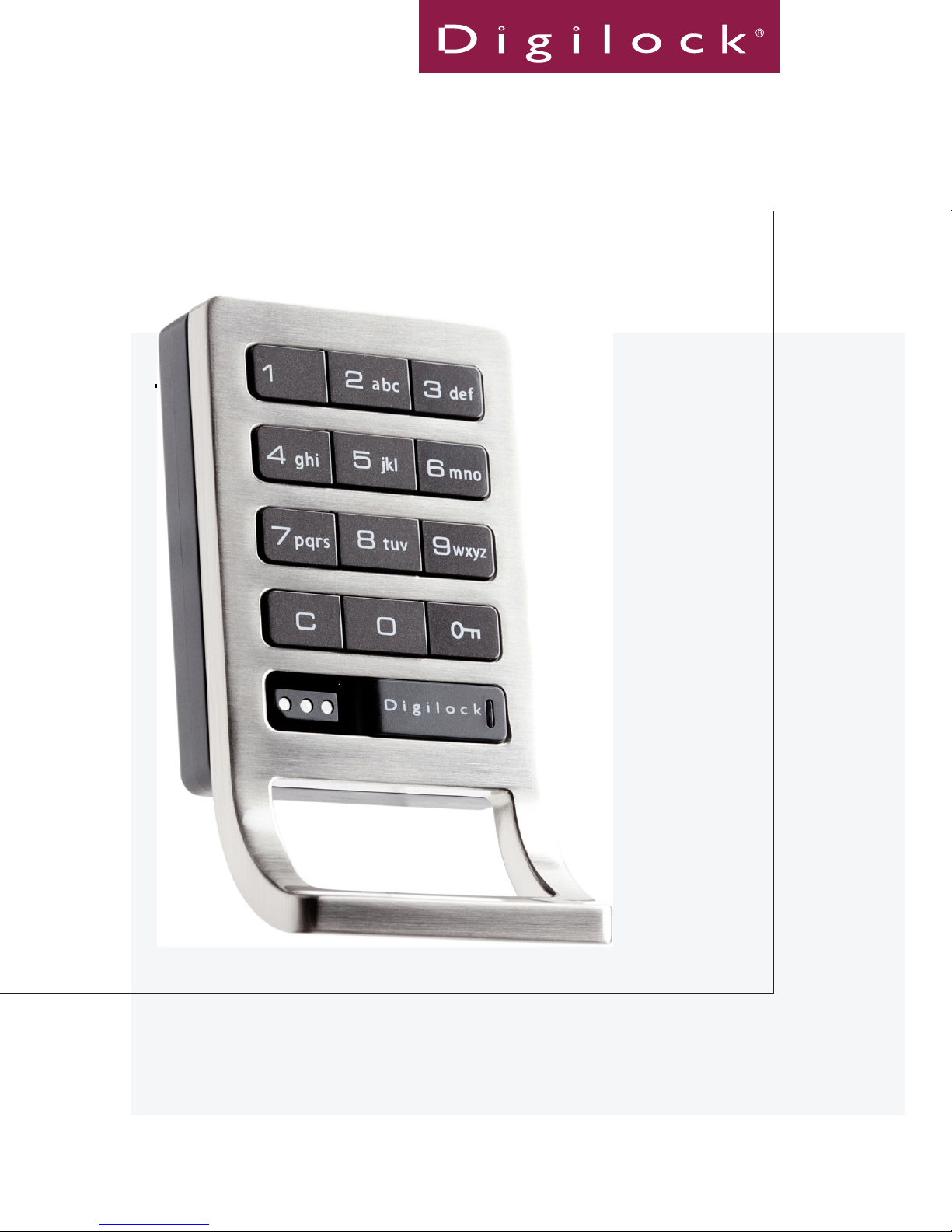
user manual
keypad standard body
DK-ATS & DK-APS
Shared & Assigned Use Functionality
Manual applies to all pull handle & no-pull handle models, surface/recess mounts and wood/metal doors
Advanced Security
Page 2

Table of Contents
Metal Door Installations __________________________________________ 2
Required Components __________________________________________ 3
Metal Door Mounting Types _____________________________________ 4
Surface Mount Metal Door Installation __________________________ 5
Recessed Cup Metal Door Installation ___________________________ 7
3-Hole Lock Plug Removal ______________________________________ 9
Padlock Hasp Removal __________________________________________ 10
Wood Surface Mount ______________________________________________ 12
Required Components __________________________________________ 13
Door Preparation Instructions _________________________________ 14
Installation Instructions ______________________________________ 18
Wood Recess Mount
Required Components __________________________________________ 23
Door Preparation Instructions _________________________________ 24
Installation Instructions ______________________________________ 28
Identifying Your Digilock Lock Function
Programming Instructions ________________________________________ 34
Lock Interface Overview ________________________________________ 35
Key Guide _____________________________________________________ 36
Initializing Locks ______________________________________________ 36
Express Registration __________________________________________ 37
Register Additional Manager Bypass Keys ________________________ 38
For Lost or Stolen Keys ________________________________________ 39
Shared Use Programming
Automatic Unlock Feature ______________________________________ 41
LED Light Function _____________________________________________ 42
Shared Use Instructions __________________________________________ 44
To Operate with a User Code ____________________________________ 45
To Operate with an ADA User Key ________________________________ 45
To Operate with a Manager Bypass Key ___________________________ 46
To Operate with a Programming Key ______________________________ 46
_______________________________________________ 22
_____________________________ 32
__________________________________________ 40
Assigned Use Programming ________________________________________ 48
To Change the User Code ________________________________________ 49
Assign an ADA User Key _________________________________________ 50
Assigned Use Instructions
To Operate with a User Code ____________________________________ 53
To Operate with an Assigned ADA User Key ________________________ 53
To Operate with a Manager Bypass Key ___________________________ 54
To Operate with a Programming Key ______________________________ 54
Troubleshooting
Common Lock Indicators ________________________________________ 57
Battery Replacement ___________________________________________ 58
Overall Dimensions ____________________________________________ 59-60
Contact Information ___________________________________________ 61
_________________________________________________ 56
_________________________________________ 52
i
Page 3

Warranty
LIMITED WARRANTY
Security People, Inc., dba Digilock (the “Company”) warrants to the original purchaser the products manufactured by the
Company (the “Product”) to be free of defects in material and workmanship, provided: (i) The Company has been notied
of such defects within two years of purchase date and been given the opportunity of inspection by return of any alleged
defective Product to the Company, or its authorized distributor, free and clear of all liens and encumbrances,
transportation prepaid, accompanied by the statement of defects and proof of purchase; and (ii) the Product has not been
modied, abused, misused, or improperly installed, maintained, and/or repaired during such period; and (iii) such defect
has not been caused by corrosion, exposure to moisture, or ordinary wear and tear. Digilock lock products are not designed
or intended for exterior use or where exposed to moisture. Any exterior use where exposed to moisture is not covered by
any warranties and voids any warranties. Any resulting damage caused by direct exterior exposure or moisture is at the
purchasers own risk.
This warranty does not cover any labor costs for installation, removal and/or re-installation of the product being serviced
or replaced under warranty. This warranty is strictly limited to product repair or replacement. This warranty does not cover
batteries, normal wear of parts and/or damage resulting from any of the following: improper installation, negligent use or
misuse of the product, use of improper voltage or current, use contrary to operating instructions, and/or disassembly, repair
or alteration by any person other than the Company service personnel.
The Company will not evaluate warranted product without rst obtaining a Return Merchandise Authorization (RMA)
number from the Company. Such returns must be prominently marked with the Return Merchandise Authorization number
and shipped prepaid (return shipping is the responsibility of the end-user). Under no circumstance is the Company liable
for incidental or consequential damages. The Company makes no other warranty, and all implied warranties including any
warranty of merchantability or tness for a particular purpose are limited to the duration of the expressed warranty period
as set forth above.
LIMIT ON LIABILITY
The Company’s maximum liability for any damages resulting from or caused by the Product, whether in contract, tort,
or otherwise is limited to the purchase price of the Product. In no event shall the company be liable for any incidental or
consequential damages of any nature arising from the sale or use of this Product, whether in contract, tort, or otherwise by
either use or purchase of the Product the user or purchaser agrees to this limit on the company’s liability.
Note: Should the Product be considered a consumer product as may be covered by the Magnusson Moss Federal Warranty
Act, please be advised that: (1) some states do not allow limitations on incidental or consequential damages or how long
an implied warranty lasts so that the above limitations may not fully apply; (2) this warranty gives specic legal rights, and
a buyer may also have other rights which may vary from state to state. For warranty service and shipping instructions,
contact the Company. The Company reserves the right to make changes in designs and specications or to make additions
or improvements on its products without notice and without incurring any obligation to incorporate them on products
previously manufactured. The Company is not responsible for any modication, addition or alteration to our products by
others. Purchaser agrees to indemnify and hold Company harmless from all claims causes of actions, lawsuits, administrative
actions, and damages (except as covered by the express limited warranty as set forth above) including reasonable attorney
fees and costs arising out of or pertaining to the Product.
ii
Page 4

1
Page 5

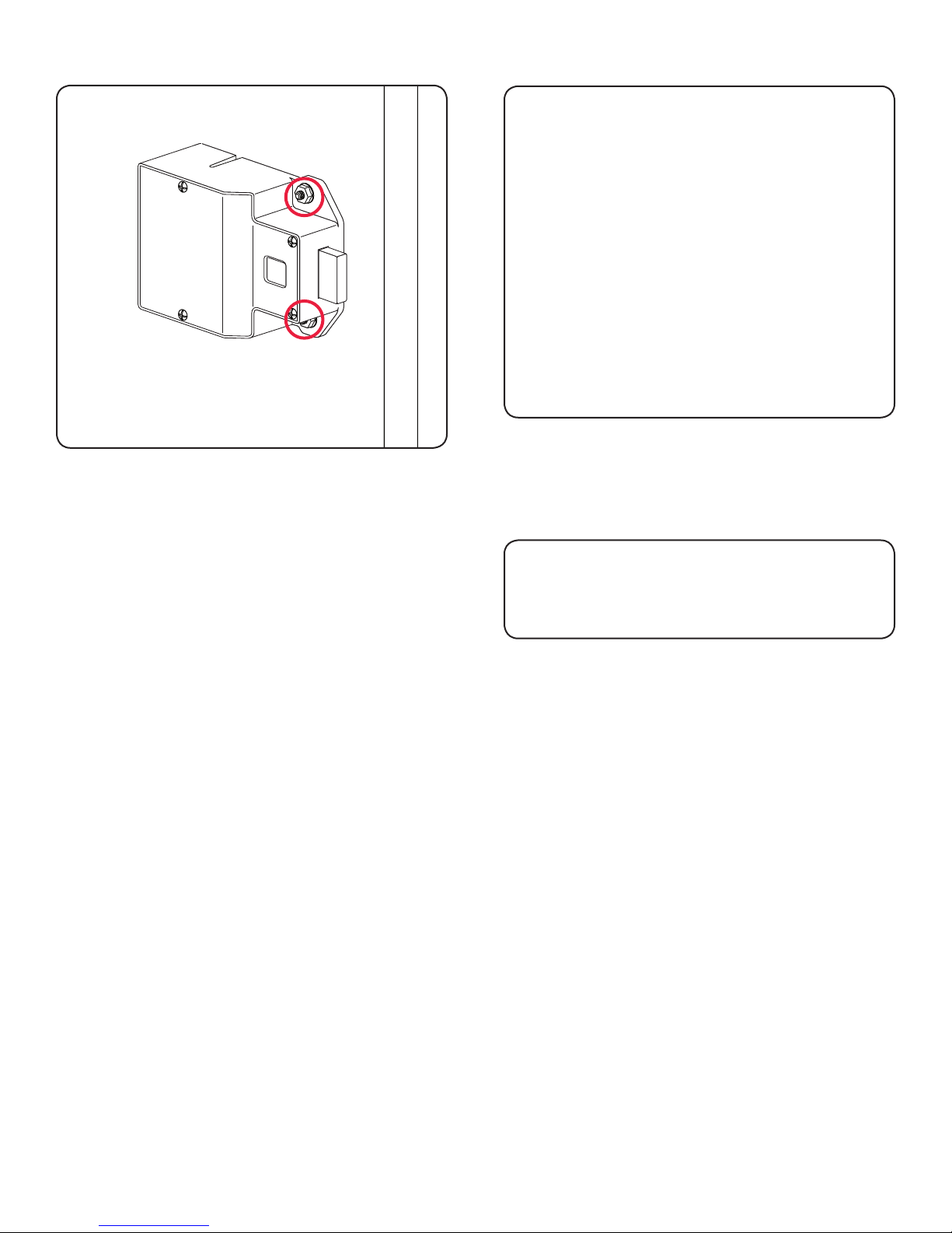
Metal Door Installations
Metal Door Mounting Types
Required Components
3-Hole Lock Plug Removal
Surface Mount Metal Door Installation
Padlock Hasp Removal
2
Recessed Cup Metal Door Installation
Page 6
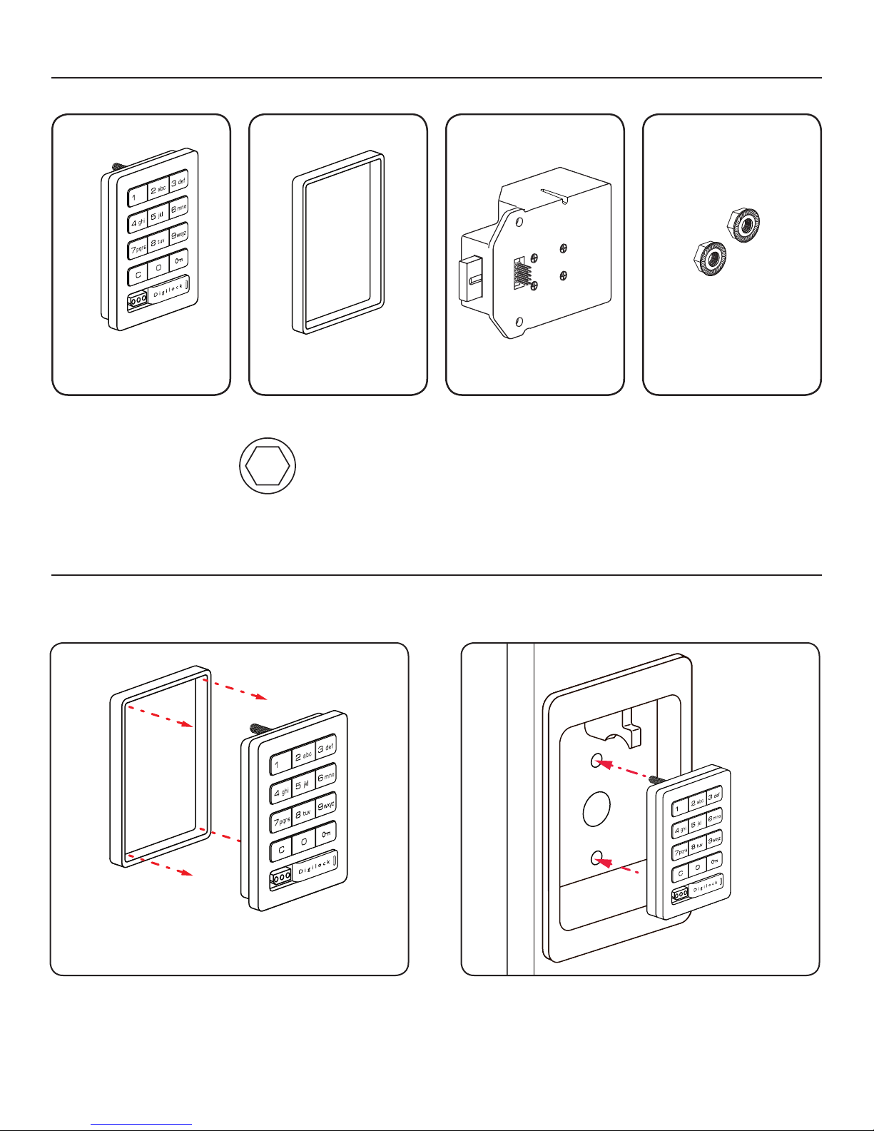
Required Components
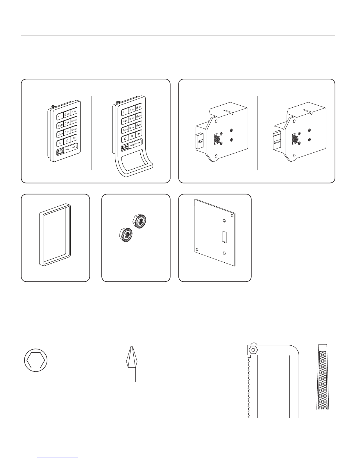
Digilock Lock Parts
Note: Conrm that all lock parts are present. If there are damaged or missing parts contact your
Digilock Product Support Specialist.
1-Front Unit with Screw Posts
No-Pull
(Both body styles shown)
With-Pull
Dead Bolt
1-Motorized Rear Unit
Dead Latch
(Both Dead Bolt & Dead Latch shown)
Optional-Back Plate2-Locking Nuts1-Plastic Ring
Required Tools
3/8” Socket
(deep socket required)
Warning: Do not use an electric screw gun during installation of the
lock unless equipped with a torque adjuster, which must be set on a
low torque setting. Otherwise, damage may be caused to the lock.
Phillips Screwdriver
Head Size #1 & #2
For padlock hasp removalFor lock installation
Hack Saw Metal File
3
Page 7
Metal Door Mounting Types
Digilock is compatible with a majority of industry standard 3-hole conguration, latch and handle types.
Some door types may need disassembly or modications prior to installation.
Recessed Cup with
Single Point Latch
Standard Lift
Multi-Point Latch
Compatible Digilock Body Types:
• Standard Body no-Pull Handle
• Standard Body with-Pull Handle
• Vertical Body no-Pull Handle
• Vertical Body with-Pull Handle
Box Locker Padlock Hasp
Compatible Digilock Body Types:
• Standard Body no-Pull Handle
• Standard Body with-Pull Handle
• Vertical Body no-Pull Handle
• Vertical Body with-Pull Handle
Recessed Cup with
Single Point Latch
Compatible Digilock Body Types:
• Standard Body no-Pull Handle
ADA Handle
Compatible Digilock Body Types:
• Standard Body no-Pull Handle
• Standard Body with-Pull Handle
• Vertical Body no-Pull Handle
• Vertical Body with-Pull Handle
Note: See page 10 for additional
modications for this door type.
Compatible Digilock Body Types:
• Standard Body no-Pull Handle
Note: See page 10 for additional
modications for this door type.
4
Compatible Digilock Body Types:
• Standard Body no-Pull Handle
Page 8
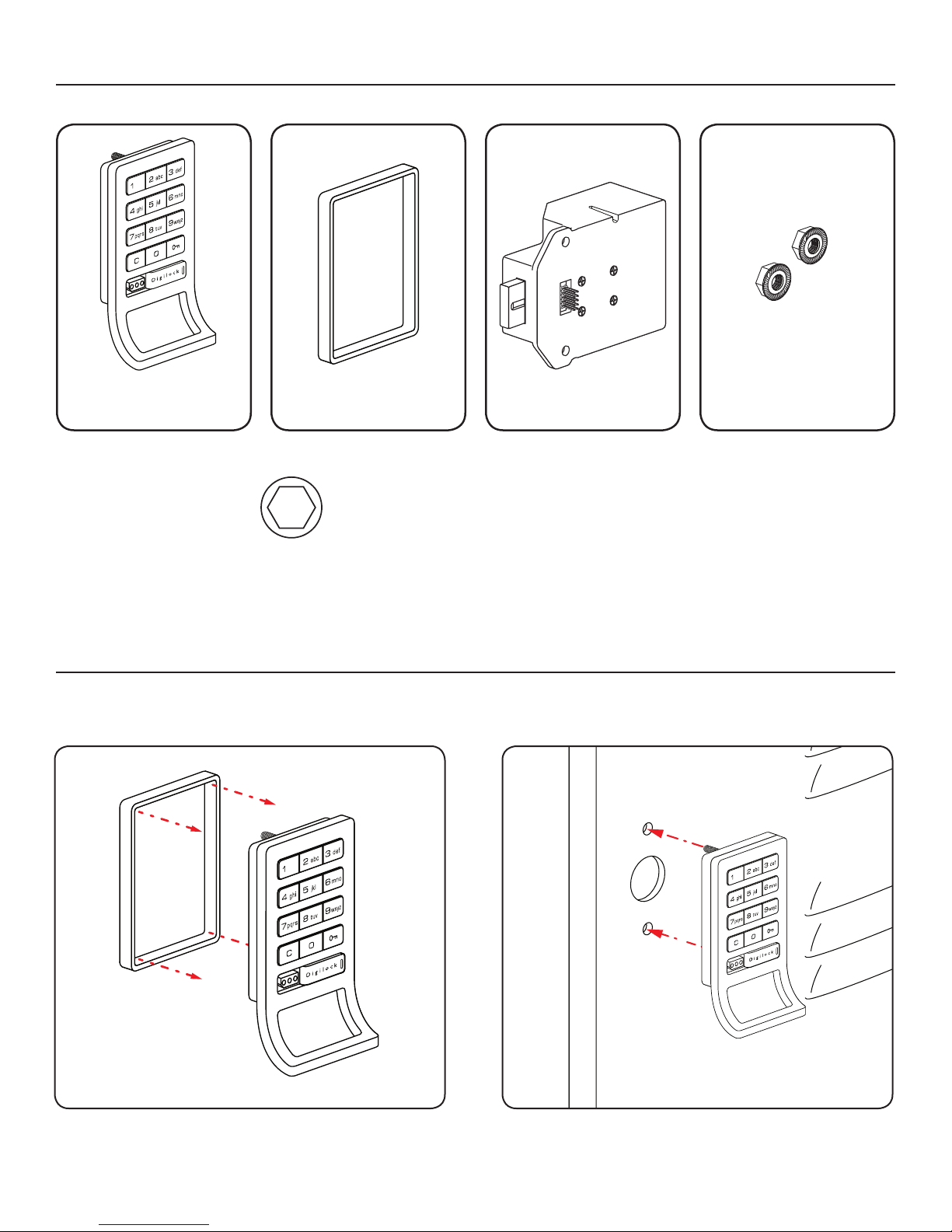
Surface Mount Metal Door Installation Parts
Note: For demonstration purposes the standard body with pull-handle and dead bolt rear unit will be shown.
A
1-Front Unit
With-Pull Handle
Required Tools
B
1-Plastic Ring
3/8” Socket
(deep socket required)
C
1-Rear Unit
D
2-Locking Nuts
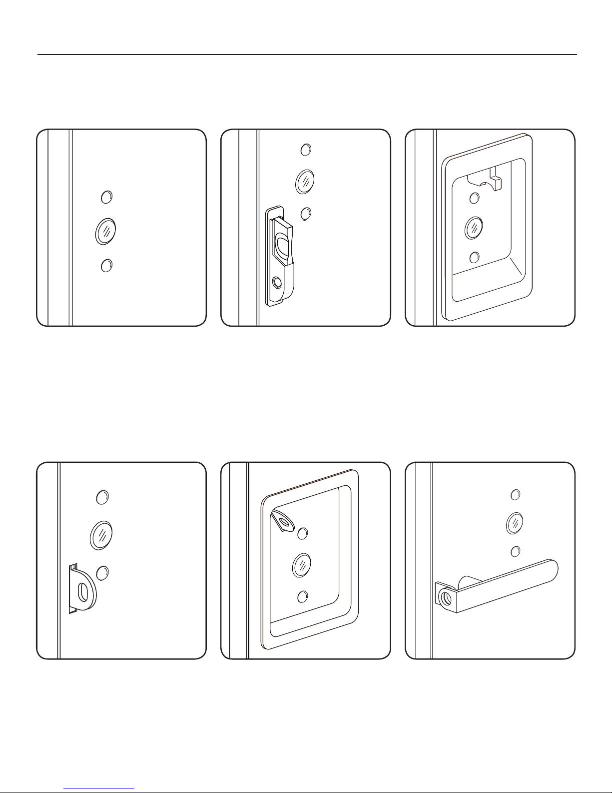
Surface Mount Metal Door Installation Steps
Note: Prior to installation the door must be clear of any obstructions. See page 9 for door prep.
Step 1
Step 2
Place the plastic ring (B) onto the front unit (A).
Place the mounting screw posts of the front unit (A)
through the lock mounting holes on the front
of the door.
5
Page 9
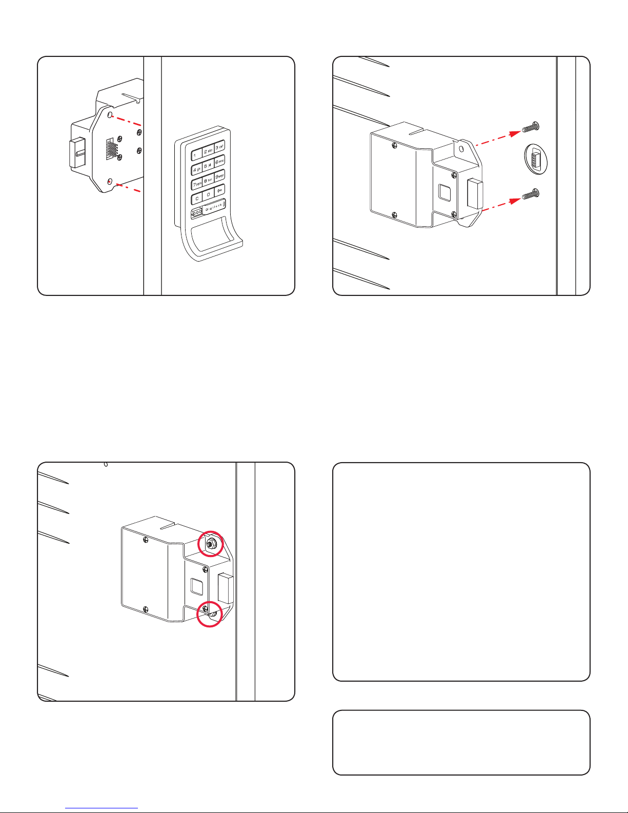
Step 3
Step 4
While holding the front unit (A) against the front of the
door, place the rear unit (C) against the rear face of
the door, aligning its mounting holes with the mounting
screw posts from the front unit.
NOTE: Do not touch the rear unit connector pins
(male connector) against any metal or other conductive
surfaces. This may short the batteries and cause
damage to the lock.
Step 5
Slide the front unit (A) and rear unit (C) together
making sure that the pins of the rear unit connector align
with the female connector of the front unit (A).
NOTE: An audible triple beep and three ashes of
the LED light indicates that the lock was connected
properly. If you do not hear these beeps, separate
the units, press the “C” button on the keypad and
reconnect the front and rear units on the door.
Step 6
Test the operation several times (as indicated
below) while the door is open. Close the door and
test the unit again. Make sure there is no binding
between the bolt/latch and the door strike plate and/
or frame. Adjust alignment if necessary.
To lock and unlock enter: = then `
NOTE: If during operation of the lock, the lock
emits 10 rapid beeps and 10 ashes of the LED
light, it is an indicator that the bolt/latch of the lock
is binding with the door strike plate and/or frame. If
this occurs, the door and/or strike plate may need to
be aligned or adjusted. It may also be an indicator
that the locking nuts are over tightened on the screw
posts or due to overtightening in Step 5.
Place the locking nuts (D) over the mounting screw
posts and hand tighten to secure the lock to the door.
Step 7
Follow the Programming section of this
manual on pages 34-39.
6
Page 10
Recessed Cup Metal Door Installation Parts
Note: For demonstration purposes the dead bolt rear unit will be shown.
A
1-Front Unit
No-Pull Handle
Required Tools
B
1-Plastic Ring
3/8” Socket
(deep socket required)
C
1-Rear Unit
D
2-Locking Nuts
Recessed Cup Metal Door Installation Steps
Note: Prior to installation the door must be clear of any obstructions. See page 9 for door prep.
Step 1
Step 2
Place the plastic ring (B) onto the front unit (A).
Place the mounting screw posts of the front unit (A)
through the lock mounting holes on the front
of the door.
7
Page 11
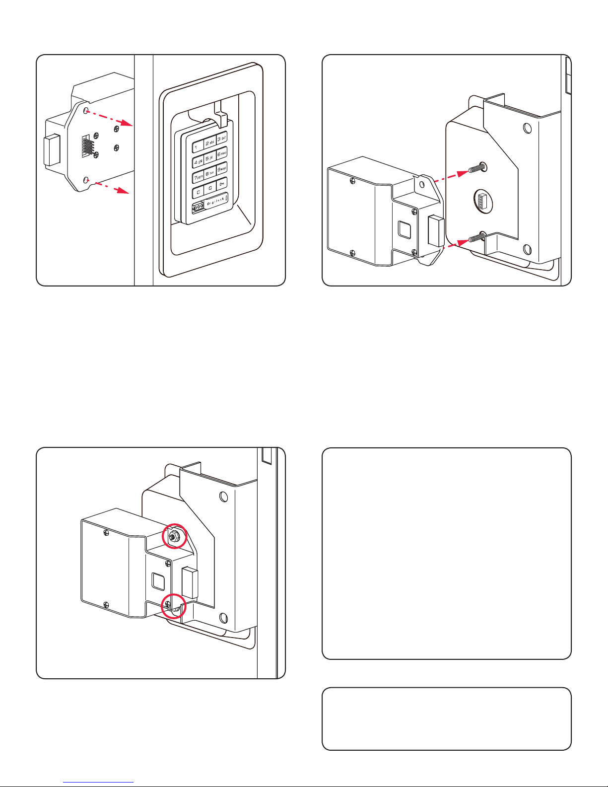
Step 3
Step 4
While holding the front unit (A) against the front of the
door, place the rear unit (C) against the rear face of
the door, aligning its mounting holes with the mounting
screw posts from the front unit.
NOTE: Do not touch the rear unit connector pins
(male connector) against any metal or other conductive
surfaces. This may short the batteries and cause
damage to the lock.
Slide the front unit (A) and rear unit (C) together
making sure that the pins of the rear unit connector align
with the female connector of the front unit (A).
NOTE: An audible triple beep and three ashes of
the LED light indicates that the lock was connected
properly. If you do not hear these beeps, separate
the units, press the “C” button on the keypad and
reconnect the front and rear units on the door.
Step 5 Step 6
Test the operation several times (as indicated
below) while the door is open. Close the door and
test the unit again. Make sure there is no binding
between the bolt/latch and the door strike plate and/
or frame. Adjust alignment if necessary.
To lock and unlock enter: = then `
NOTE: If during operation of the lock, the lock
emits 10 rapid beeps and 10 ashes of the LED
light, it is an indicator that the bolt/latch of the lock
is binding with the door strike plate and/or frame. If
this occurs, the door and/or strike plate may need to
be aligned or adjusted. It may also be an indicator
that the locking nuts are over tightened on the screw
posts or due to overtightening in Step 5.
Place the locking nuts (D) over the mounting screw
posts and hand tighten to secure the lock to the door.
Step 7
Follow the Programming section of this
manual on pages 34-39.
8
Page 12
There are 4 Types of Door Mounts that Require Disassembly or Modications Prior to
your Digilock Lock Installation.
• Single or Standard Lift with Mounted Plug
• Recessed Cup with Multi-Point Latch
• Box Locker Padlock Hasp
• Recessed Cup with Single Point Latch
Door Prep - 3-Hole Lock Plug Removal
Most metal lockers will come with a 3 point dial combo metal plug. This will need to be removed in
order to install your Digilock Lock.
Single or Standard Lift with Mounted Plug
Rear View of
Locker Door
w/Lock Plug
Front View of
Locker Door
w/Lock Plug
Recessed Cup with Multi-Point Latch
Rear View of
Locker Door
w/Lock Plug
Front View of
Locker Door
w/Lock Plug
9
Page 13
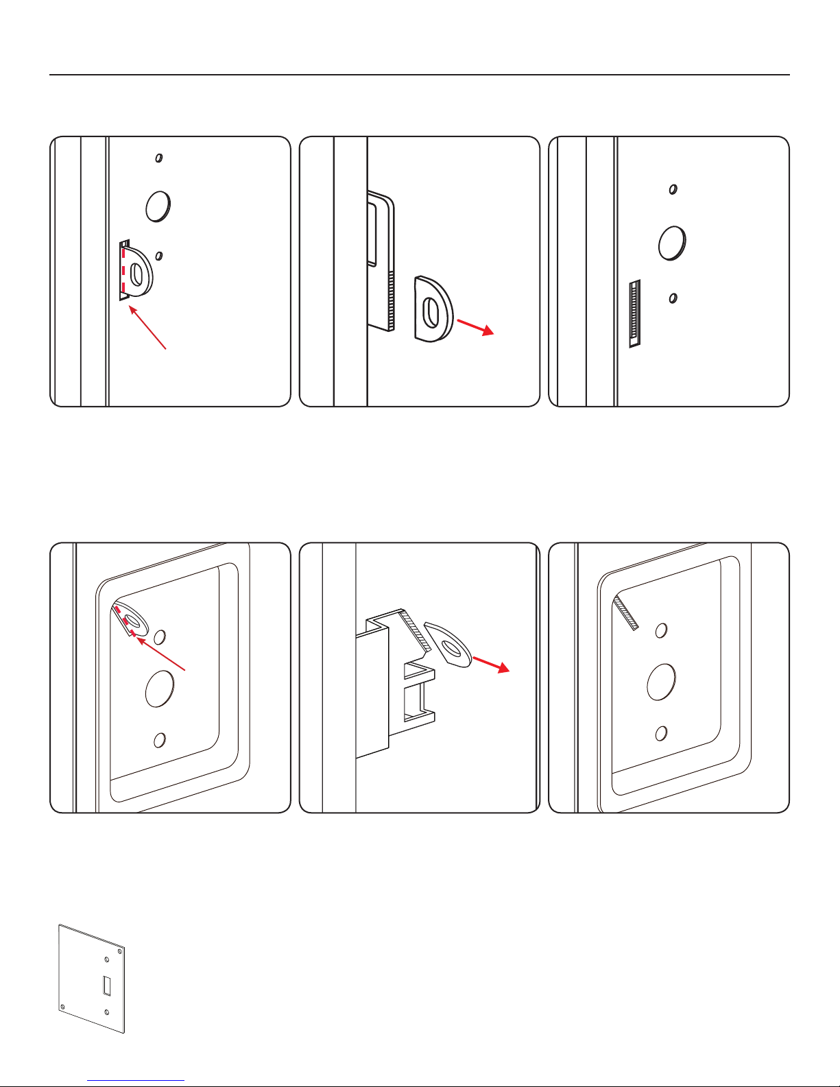
Door Prep - Padlock Hasp Removal
Required Tools: Hack Saw and Metal File.
Box Locker Padlock Hasp
Mark Here
With the locker door closed, mark
the appropriate area (as indicated
above) to remove the padlock hasp.
The cut-line needs to clear the front
face of the locker door.
With the locker door open, use the
hand-held grinder or the hack saw to
cut the protruding part of the padlock
hasp as demonstrated above.
Recessed Cup with Single Point Latch
Mark Here
Smooth out any rough or sharp edges
with a metal le. With the locker door
closed, inspect the locker to ensure
that nothing is protruding above the
face of the locker door.
With the locker door closed, mark
the appropriate area (as indicated
above) to remove the padlock hasp.
The cut-line needs to clear the front
face of the locker door.
Note:
Digilock manufactures an optional Back Plate
to cover the padlock hasp hole.
For more information please contact your
Digilock Product Specialist.
With the locker door open, use the
hand-held grinder or the hack saw to
cut the protruding part of the padlock
hasp as demonstrated above.
10
Smooth out any rough or sharp edges
with a metal le. With the locker door
closed, inspect the locker to ensure
that nothing is protruding above the
face of the locker door.
Page 14

11
Page 15

12
Installation Instructions
Wood Surface Mount
Required Components
Door Preparation Instructions
Page 16

Required Components
Digilock Lock Parts
Note: Conrm that all lock parts are present. If there are damaged or missing parts contact your
Digilock Product Support Specialist.
1-Front Unit with Nut Posts
No-Pull
(Both body styles shown)
With-Pull
Dead Bolt
1-Motorized Rear Unit
Dead Latch
(Both Dead Bolt & Dead Latch shown)
2-Split Lock Washers2-Phillips Head Screws*1-Pin Extender1-Plastic Ring
* Screws lengths vary based on door thickness.
Optional
Required Tools
For lock installation
Phillips Screwdriver
Head Size #1 & #2
1-Strike Plate with
3-Self-Tapping Screws
For door preparation
Power Drill
Drill Bits: 1/16”
5/16”
3/4”
Warning: Do not use an electric screw gun during installation of the lock unless equipped with a torque adjuster,
which must be set on a low torque setting. Otherwise, damage may be caused to the lock.
13
Page 17
Template
Center line
Strike
Plate
Center
Edge of Strike Plate
Strike Edge Marker
Template
Strike
Plate
Center
Edge of Strike Plate
Strike Edge Marker
Mark
Template
Mark Door Edge
Mark Door Edge
Door Edge
Drawn
Marker
Drill x2
5/16” 0.3125 in
(7.94 mm)
Drill 3/4” - 0.75 in
(19.1 mm)
Template
Center line
Plate
Center
Mark
Template
Mark Door Edge
Door Edge
Drawn
Marker
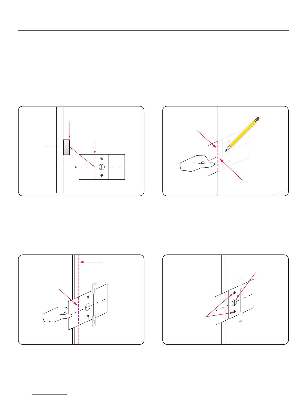
Door Preparation Instructions
Note: Skip these steps if a Digilock compatible industry standard 3-hole conguration already
exists on your door.
Lock Mounting Holes
Required Items: Lock Mounting Drill Template: See page 16 (print and cut out template)
Pencil: To mark door and template
Adhesive Tape: To secure template to door (masking tape recommended)
Required Tools: Power Drill: To drill holes
Drill Bits: 5/16” and 3/4”
Step 1
Step 2
Place the template over the strike plate. Using the
corresponding markers on the template, align the
template to the center and edge of the strike plate as
shown above.
Note: Do not remove the template, it is required for
“Step 2”.
Step 3
Place the template over the door face and align the
template using the marks drawn as directed on “Step 2”.
Note: Secure the template to the door face with tape
for the next step.
With the positioned template, close the door. Draw a
line on the template to mark the door edge. Then using
the template “Center Line” mark a reference line on the
door edge.
Step 4
Mark the door face to drill the necessary holes.
Using the template drill markers, drill two 5/16” holes as
indicated above. Then, if not present, drill one 3/4” hole.
14
Page 18
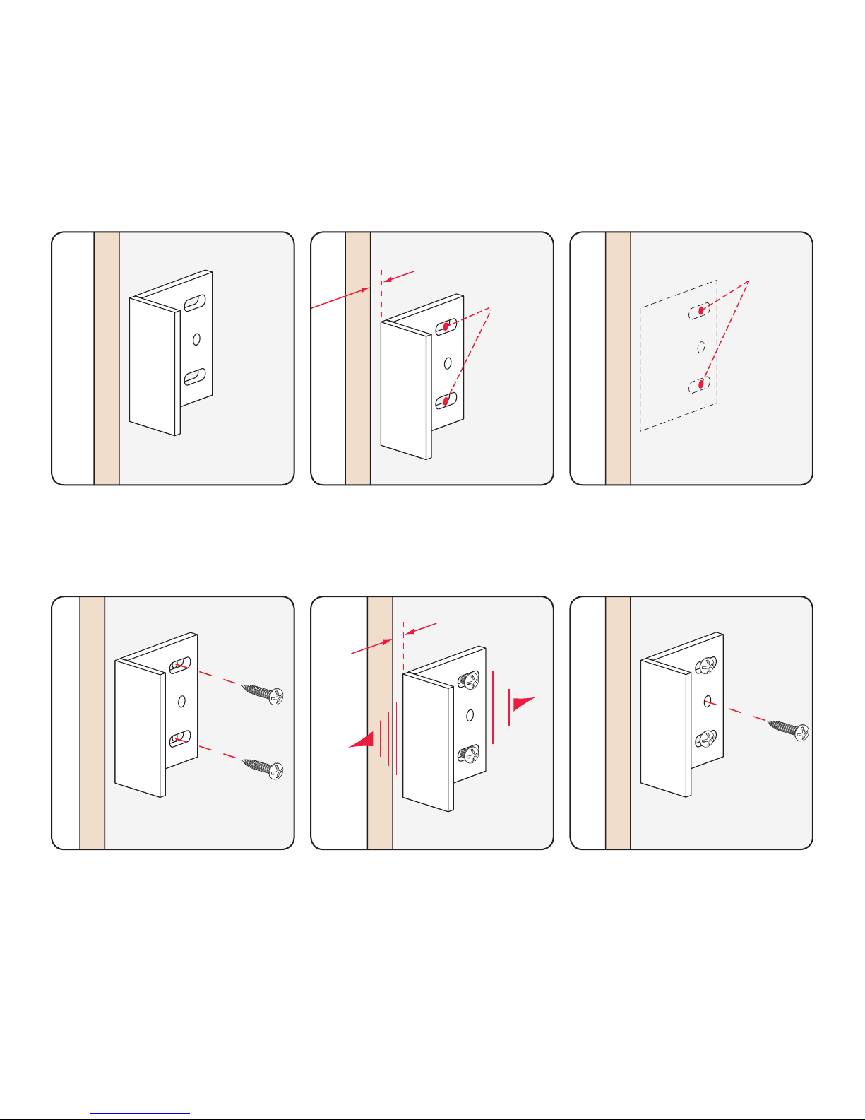
Strike Plate Installation
Door Frame
Door Frame
0.125 in
(3.18 mm)
Mark Here
Door Frame
Drill Pilot
Holes Here
Door Frame
Door Frame
0.125 in
(3.18 mm)
Door Frame
Note: Skip these steps if a Digilock compatible strike plate is already present.
Required Hardware & Tools:
• Digilock Strike Plate with 3-Self-Tapping Screws
• Pencil: To mark screw holes
• Phillips Screwdriver: #1 or Cordless drill (with torque adjustment) and a phillips driver recommended
1
Position the Strike Plate on the
door frame centering it adjacent
to the center of the mounting
holes.
4
2
Allow 1/8” or 0.125 in (3.18 mm)
from door edge and mark pilot
holes for the adjustment slots as
shown above.
5
3
Drill 0.25 in (6.35 mm) pilot holes
using a 1/16 in drill bit.
6
Position the Strike Plate and 2
self-tapping screws into the 2
outer adjustment slots.
NOTE: Do not tighten the screws.
Adjust the Strike Plate to the
proper position (as shown in Step
2). Then tighten the 2 screws in
the adjustment slots.
15
Place and tighten the third screw
into the center Strike Plate hole to
lock the Strike Plate into position.
Page 19
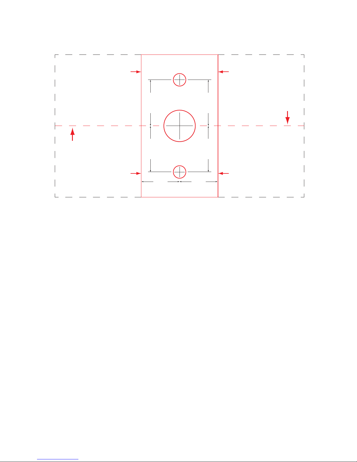
Lock Mounting Drill Template
Note: Use the corresponding side of the template for mounting the lock.
All measurements in thousandths
ALIGN EDGE OF
STRIKE PLATE HERE
FOR LEFT
CLOSING DOOR
CENTER LINE
of an inch and millimeters
)mm( 9.72
001.1
)mm( 9.72
001.1
.300
7.62 (mm)
use 5/16" bit
.750
19.05 (mm)
use 3/4" bit
ALIGN EDGE OF
STRIKE PLATE HERE
FOR RIGHT
CLOSING DOOR
001.1
)mm( 9.72
001.1
)mm(9.72
CENTER LINE
ALIGN EDGE OF
STRIKE PLATE HERE
FOR LEFT
CLOSING DOOR
.905
23 (mm)
.300
7.62 (mm)
.905
23 (mm)
ALIGN EDGE OF
STRIKE PLATE HERE
FOR RIGHT
CLOSING DOOR
NOTE: Templates may not print to scale. Double check all measurements before drilling door.
If printing this page, turn off any auto scaling in printer setup and print at 100%.
16
Page 20

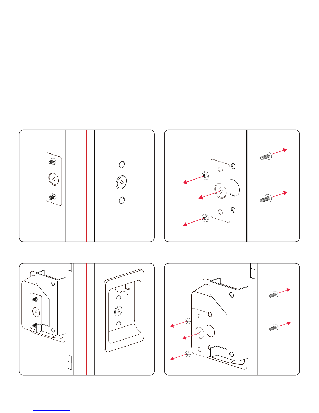
Door Prep Requirements
Before installing, your door must be prepped with a Strike Plate (Figure A)
and lock mounting holes (Figure B).
NOTE: See Door Preparation Instructions for more information on pages 14-16.
FIG. BFIG. A
Strike Plate
Lock Handing
To change handing:
1) Disconnect the front unit from the rear unit.
2) Hold down
3) Reconnect the units with the desired handing or connect them as part of the installation.
Left Handed
NOTE: If the handing has been previously registered by connecting and operating the lock prior to installation on the door,
the lock may not function if the initial handing is different than the installation on the door. Both bolt and latch locks
can be right or left handed. Bolt shown above for demonstration purposes.
Button for one full second.
=
Right Handed
17
Page 21

Installation Instructions
Digilock Wood Surface Mount Lock Parts
Note: For demonstration purposes the standard body with pull-handle and dead bolt rear unit will be shown.
A
D
1-Front Unit
B
E
1-Plastic Ring
C
1-Rear Unit
F
1-Pin Extender
* Screws lengths vary based on door thickness.
Required Tools
Phillips Screwdriver
Head Size #2
2-Phillips Head Screws*
18
2-Split Lock Washers
Page 22

Step 1
Step 1
Place the plastic ring (B) onto the front unit (A).
Step 3
Place the pin extender (D) on the connector pins of
the rear unit (C).
NOTE: Do not touch the rear unit connector pins (male
connector) against any metal or other conductive
surfaces. This may short the pins and cause damage
to the lock.
Step 4
Place the split lock washers (F) on the phillips head
screws (E) and place the phillips head screws (E)
with washers through the holes on the rear unit (C)
as shown above.
Place the mounting nut posts of the front unit (A)
through the lock mounting holes on the front of the
door.
19
Page 23

Step 5
Step 6
While holding the front unit (A) against the front of the
door, bring the rear unit (C) against the rear face of
the door, aligning the screws in the rear unit with the
mounting nut posts from the front unit.
NOTE: An audible triple beep and three ashes of the
LED indicates that the lock was connected properly. If
you do not hear these beeps, separate the units, press
the “C” button on the keypad and reconnect the front
and rear units on the door.
Test the operation several times (as indicated
below) while the door is open. Close the door and
test the unit again. Make sure there is no binding
between the bolt/latch and the door strike plate and/
or frame. Adjust alignment if necessary.
To lock and unlock enter: = then `
NOTE: If during operation of the lock, the lock
emits 10 rapid beeps and 10 ashes of the LED
light, it is an indicator that the bolt/latch of the lock
is binding with the door strike plate and/or frame. If
this occurs, the door and/or strike plate may need to
be aligned or adjusted. It may also be an indicator
that the mounting screws are over tightened or due
to overtightening in Step 6.
Slide the front unit (A) and rear unit (C) together
making sure that the pins of the rear unit connector
align with the pins of the front unit connector and hand
tighten the mounting screws.
WARNING: Do not overtighten screws.
Step 8Step 7
Follow the Programming section of this
manual on pages 34-39.
20
Page 24

21
Page 25

22
Installation Instructions
Wood Recess Mount
Required Components
Door Preparation Instructions
Page 26

Required Components
Digilock Lock Parts
Note: Conrm that all lock parts are present. If there are damaged or missing parts contact your
Digilock Product Support Specialist.
1-Front Unit with Screw Posts
No-Pull
(Both body styles shown)
With-Pull
Dead Bolt
Optional
1-Motorized Rear Unit
Dead Latch
(Both Dead Bolt & Dead Latch shown)
1-Strike Plate with
3-Self-Tapping Screws
Optional-Back Plate2-Locking Nuts1-Pin Extender
Required Tools
For lock installation
3/8” Socket
(deep socket required)
Phillips Screwdriver
Head Size #1 & #2
Warning: Do not use an electric screw gun during installation of the lock unless equipped with a torque adjuster,
which must be set on a low torque setting. Otherwise, damage may be caused to the lock.
For door preparation
Power Drill
Drill Bits: 1/16”
5/16”
3/4”
23
Page 27

Template
Strike
Plate
Center
Edge of Strike Plate
Strike Edge Marker
Mark
Template
Mark Door Edge
Template
Center line
Plate
Center
Mark
Template
Mark Door Edge
Door Edge
Drawn
Marker
Template
Center line
Strike
Plate
Center
Edge of Strike Plate
Strike Edge Marker
Mark Door Edge
Door Edge
Drawn
Marker
Drill x2
5/16” 0.3125 in
(7.94 mm)
Drill 3/4” - 0.75 in
(19.1 mm)
Door Preparation Instructions
Note: Skip these steps if a Digilock compatible industry standard 3-hole conguration already
exists on your door.
Lock Mounting Holes
Required Items: Lock Mounting Drill Template: See page 26 (print and cut out template)
Pencil: To mark door and template
Adhesive Tape: To secure template to door (masking tape recommended)
Required Tools: Power Drill: To drill holes
Drill Bits: 5/16” and 3/4”
Step 1
Step 2
Place the template over the strike plate. Using the
corresponding markers on the template, align the
template to the center and edge of the strike plate as
shown above.
Note: Do not remove the template, it is required for
“Step 2”.
Step 3
Place the template over the door face and align the
template using the marks drawn as directed on “Step 2”.
Note: Secure the template to the door face with tape
for the next step.
With the positioned template, close the door. Draw a
line on the template to mark the door edge. Then using
the template “Center Line” mark a reference line on the
door edge.
Step 4
Mark the door face to drill the necessary holes.
Using the template drill markers, drill two 5/16” holes as
indicated above. Then, if not present, drill one 3/4” hole.
24
Page 28

Strike Plate Installation
Door Frame
Door Frame
0.125 in
(3.18 mm)
Mark Here
Door Frame
Drill Pilot
Holes Here
Door Frame
Door Frame
0.125 in
(3.18 mm)
Door Frame
Note: Skip these steps if a Digilock compatible strike plate is already present.
Required Hardware & Tools:
• Digilock Strike Plate with 3-Self-Tapping Screws
• Pencil: To mark screw holes
• Phillips Screwdriver: #1 or Cordless drill (with torque adjustment) and a phillips driver recommended
1
Position the Strike Plate on the
door frame centering it adjacent
to the center of the mounting
holes.
4
2
Allow 1/8” or 0.125 in (3.18 mm)
from door edge and mark pilot
holes for the adjustment slots as
shown above.
5
3
Drill 0.25 in (6.35 mm) pilot holes
using a 1/16 in drill bit.
6
Position the Strike Plate and 2
self-tapping screws into the 2
outer adjustment slots.
NOTE: Do not tighten the screws.
Adjust the Strike Plate to the
proper position (as shown in Step
2). Then tighten the 2 screws in
the adjustment slots.
25
Place and tighten the third screw
into the center Strike Plate hole to
lock the Strike Plate into position.
Page 29

Lock Mounting Drill Template
Note: Use the corresponding side of the template for mounting the lock.
All measurements in thousandths
ALIGN EDGE OF
STRIKE PLATE HERE
FOR LEFT
CLOSING DOOR
CENTER LINE
of an inch and millimeters
)mm( 9.72
001.1
)mm( 9.72
001.1
.300
7.62 (mm)
use 5/16" bit
.750
19.05 (mm)
use 3/4" bit
ALIGN EDGE OF
STRIKE PLATE HERE
FOR RIGHT
CLOSING DOOR
001.1
)mm( 9.72
001.1
)mm(9.72
CENTER LINE
ALIGN EDGE OF
STRIKE PLATE HERE
FOR LEFT
CLOSING DOOR
.905
23 (mm)
.300
7.62 (mm)
.905
23 (mm)
Door Mortise Template: Standard Body
mm
)
)
2.19 in
(
56
mm
)
.300 (8
2.01 in (51 mm
1.98 in (50
)
mm
2x
ALIGN EDGE OF
STRIKE PLATE HERE
FOR RIGHT
CLOSING DOOR
2.72 in (69 mm
2.68 in (68
mm
)
)
NOTE: Templates may not print to scale. Double check all measurements before drilling door.
If printing this page, turn off any auto scaling in printer setup and print at 100%.
)
.75 (19
mm
0.400/0.425 in DEEP
(
10/11
mm
)
R 0.125(3
mm
4x
)
26
Page 30

Door Prep Requirements
Before installing, your door must be prepped with a Strike Plate (Figure A) and
must be Mortised to receive recessed lock (Figure B).
NOTE: See Door Preparation Instructions for more information on page 24-26.
FIG. BFIG. A
Strike Plate
Lock Handing
To change handing:
1) Disconnect the front unit from the rear unit.
2) Hold down
3) Reconnect the units with the desired handing or connect them as part of the installation.
Left Handed
NOTE: If the handing has been previously registered by connecting and operating the lock prior to installation on the door,
the lock may not function if the initial handing is different than the installation on the door. Both bolt and latch locks
can be right or left handed. Bolt shown above for demonstration purposes.
Button for one full second.
=
Right Handed
27
Page 31

Installation Instructions
Digilock Wood Recess Mount Lock Parts
Note: For demonstration purposes the standard body with pull-handle and dead bolt rear unit will be shown.
A
D
1-Front Unit
B
1-Rear Unit
C
1-Pin Extender
2-Locking Nuts
Required Tools
3/8” Socket
(deep socket required)
28
Page 32

Step 1
Step 2
Place the pin extender (C) on the connector pins of the
rear unit (B).
NOTE: Do not touch the rear unit connector pins (male
connector) against any metal or other conductive
surfaces. This may short the pins and cause damage
to the lock.
Step 3
Place the mounting screw posts of the front unit (A)
through the lock recessed mounting holes on the
front of the door.
Step 4
Place the rear unit (B) against the rear face of the door,
aligning its mounting holes with the mounting screw
posts from the front unit.
NOTE: An audible triple beep and three ashes of the
LED indicates that the lock was connected properly. If
you do not hear these beeps, separate the units, press
the “C” button on the keypad and reconnect the front
and rear units on the door.
Slide the front unit (A) and rear unit (B) together
making sure that the pins of the rear unit connector align
with the female connector of the front unit (A).
29
Page 33
Step 5
Place the locking nuts (D) over the mounting screw
posts and hand tighten to secure the lock to the door.
Step 6
Test the operation several times (as indicated
below) while the door is open. Close the door and
test the unit again. Make sure there is no binding
between the bolt/latch and the door strike plate and/
or frame. Adjust alignment if necessary.
To lock and unlock enter: = then `
NOTE: If during operation of the lock, the lock
emits 10 rapid beeps and 10 ashes of the LED
light, it is an indicator that the bolt/latch of the lock
is binding with the door strike plate and/or frame. If
this occurs, the door and/or strike plate may need to
be aligned or adjusted. It may also be an indicator
that the locking nuts are over tightened on the screw
posts or due to overtightening in Step 5.
WARNING: Do not overtighten screws.
Step 7
Follow the Programming section of this
manual on pages 34-39.
30
Page 34

31
Page 35

32
Assigned Use Lock Model
Identifying Your Digilock
Lock Function
Shared Use Lock Model
Page 36

Identifying Your Digilock Lock Function
Before initializing/programming your locks it is important to identify the functionality of the lock you
have in order to determine which programming instructions will be applicable.
Shared Use Lock Model
• The rear unit has a Dead Bolt.
• When you press the = then ` buttons
the bolt will extend locking the lock.
• When you press the = then ` buttons a
second time the bolt retracts, remaining in the
unlocked position.
• Follow the programming and operating
instructions on pages 34-39 and 40-46.
Dead Bolt
Assigned Use Lock Model
• The rear unit has a Dead Latch.
• When you press the = then ` buttons
the latch retracts allowing you to open the
locker door.
• After 6-8 seconds the retracted latch will
extend and upon closing the door will lock.
• Follow the programming and operating
instructions on pages 34-39 and 49-54.
Dead Latch
33
Page 37

Programming Instructions
USE QR CODES TO WATCH THE VIDEO VERSION
Lock Interface Overview
Key Guide
Initializing Locks
Register Additional Manager Bypass Keys
Express Registration
For Lost or Stolen Keys
3434
Page 38

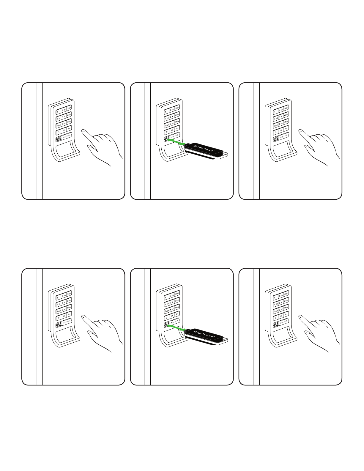
Lock Interface Overview
Key Insertion
Digilock Logo must face up.
C Button Key Symbol Button
Alpha Numeric Keypad
Key Insert
Pull Handle
Key Guide:
Programming Key (Yellow)
• Registers Manager Bypass Key(s)
• Provides external power
• Each lock accepts only (1) Programming Key
• Minimum of (1) required per location
LED light Usage Indicator
Manager Bypass Key (Black)
• Provides management access
• Provides external power
• Each lock accepts up to (25) Manager Key(s)
• Minimum of (1) required per location
3rd Generation - Programming Key (Red)
• Registers Manager Bypass Key(s)
• Provides external power
• Each lock accepts only (1) Programming Key
• Minimum of (1) required per location
ADA User Key (Blue)
• ADA Compliant User Key
• Optional
35
Page 39

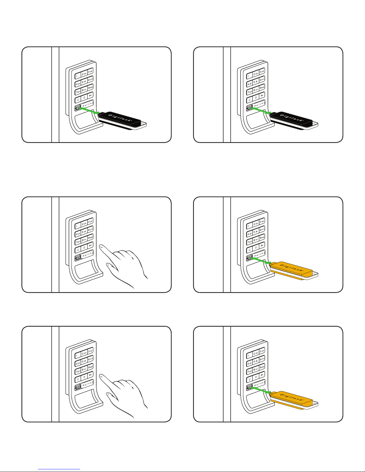
Initializing Lock(s)
These steps will initialize and register one or more Manager Bypass Keys to one lock.
1
Start at locker #1. Touch the Programming Key (yellow)
to the key slot for one full second.
A two tone beep will be heard and the LED light will
turn solid. The lock is now in programming mode.
3
2
While the LED light is solid, touch each of the
Manager Bypass Key(s) (black) to the key slot one at
a time.
A single beep will be heard each time a new key is
touched to the lock indicating acceptance.
4
When you have nished touching all of your Manager
Bypass Keys (black), end programming mode by
reinserting the Programming Key (yellow).
A two tone beep will be heard and the LED light will
turn off. This lock is initialized and programmed with
the Manager Bypass Key(s).
Test the programming by touching each Manager
Bypass Key(s) to the key slot of lock. If programming
is successful, the lock will operate with each Manager
Bypass Key(s) (black).
36
Page 40

Express Registration
These steps help speed registration and initialization of multiple new locks.
1
Go to the lock that was programmed in
Step 1 on page 36.
Press: = ` 66 `
LED light will ash.
2
Touch the Programming Key (yellow) to the key slot.
A two tone beep will be heard and the LED light will
turn off.
The Programming Key (yellow) has copied the lock
programming information from locker #1 and is now
ready to program all other locks in the locker room.
3
Touch the Programming Key (yellow) to the key slot
of all locks to be programmed.
A two tone beep will be heard and the LED light will
ash once to indicate successful programming of
each lock.
4
Test the programming by touching the Manager
Bypass Key(s) (black) to the key slot of the lock(s).
If programming is successful, the lock will operate.
37
Page 41

Register Additional Manager Bypass Keys
To add additional Manager Bypass Key(s) to locks that have been previously programmed.
1
Go to a lock that has been programmed with existing
Manager Bypass Keys.
Press: = ` 55 `
LED light will ash.
2
Touch the Programming Key (yellow) to the key slot of
the lock for one full second.
The LED light will turn solid.
3
Touch each additional Manager Bypass Key (black) to
the lock one at a time.
A single beep will be heard each time a new key is
touched to the lock indicating acceptance.
This lock is now programmed with the additional
5
Manager Bypass Key(s). Test the programming
by touching the Manager Bypass Key(s) (black)
to the key slot of the lock(s). If programming is
successful, the lock will operate.
4
Touch the Programming Key (yellow) to the key slot
of the lock for one full second.
A two tone beep will be heard and the LED light will
turn off.
Repeat Steps 1-4 to all additional locks or use
6
Express Registration Instructions on page 37 to
speed registration of newly added keys.
38
Page 42

For Lost or Stolen Keys
For a Lost Programming Key
Contact your Digilock Product Support Representative
to order a replacement Programming Key.
For a Lost Manager Bypass Key(s)
The following steps will erase registration of all Manager Bypass Keys.
1
Collect all remaining Manager Bypass Key(s) or
order additional keys from your Digilock product
representative.
3
2
Go to locker #1 and press: = ` 55 `
The LED light will ash.
4
Touch the Programming Key (yellow) to the key slot
for one full second.
The LED light will turn solid.
Note: All remaining Manager Bypass Key(s) must be re-registered. Please follow instructions
“To Re-register Additional Manager Bypass Key(s)” on page 38.
Touch the Programming Key (yellow) to the key slot
for one full second.
A two tone beep will be heard and the LED light will
turn off. Any previously registered Manager Bypass
Keys will be erased on this lock.
39
Page 43

Shared Use Programming
USE QR CODES TO WATCH THE VIDEO VERSION
Automatic Unlock Feature
LED Light Function
40
Page 44
Automatic Unlock Feature
Automatic Unlock is an option that will only activate when it is programmed. It can be disabled at any
time with a registered Manager Bypass Key.
To Enable Automatic Unlock
1
Press: = then `
2
Touch a registered Manager Bypass
Key (Black) to the key slot of the lock
for one full second.
A two tone beep will be heard and the
LED light will turn solid.
To Disable Automatic Unlock
3
Press the 1 through 8 for the
number of hours then press:
A two tone beep will be heard and
the LED light will turn off.
`*.
1
Press: = then `
Advanced Security locks do not require the ` to be pressed.
*
2
Touch the Manager Key (Black) to
the key slot of the lock for one full
second.
A two tone beep will be heard and
the LED light will turn solid.
3
Press the 9 to disable the AutoUnlock feature then press: `*.
A two tone beep will be heard and
the LED light will turn off. Disabling
the Automatic Unlock will also enable
the LED light (see page 42).
41
Page 45

LED light Function
The purpose of the LED light is to provide a usage indicator for when the locks are being used in a
shared use environment. In the event that the lock(s) are assigned to one user (converted to assigned
use) it is advisable to disable the LED light with a registered Manager Bypass Key in order to extend
the battery life.
To Disable the Flashing LED light
1
Press: = then `
2
Touch a registered Manager Bypass
Key (Black) to the key slot of the lock
for one full second.
A two tone beep will be heard and the
LED light will turn solid.
To Enable the Flashing LED light
3
Press the 0 to disable the Flashing
LED light feature
A two tone beep will be heard and
the LED light will turn off.
then press: `*.
1
Press: = then `
Advanced Security locks do not require the ` to be pressed.
*
2
Touch the Manager Key (Black) to
the key slot of the lock for one full
second.
A two tone beep will be heard and
the LED light will turn solid.
3
Press the 9 to enable the Flashing
LED light feature then press: `*.
A two tone beep will be heard and
the LED light will turn off. Enabling
the LED light will also disable the
Automatic Unlock (see page 41).
42
Page 46

43
Page 47

44
To Operate with a Programming Key
Shared Use Instructions
Shared Use Lock Use Instructions
USE QR CODES TO WATCH THE VIDEO VERSION
To Operate with a User Code
To Operate with an ADA User Key
To Operate with a Manager Bypass Key
Page 48

To Operate with a User Code
To Lock
1) Find an available lock.
2) Press: = _ _ _ _ `
(any four-digit code)
Note: If an incorrect User Code is entered three consecutive times, the lock will go into “Sleep State”
for one full minute or until a registered Manager Key (black) is touched to the lock.
To Unlock
1) At same lock.
2) Press: = _ _ _ _ `
(same code used to lock)
To Operate with an ADA User Key
To Lock
1) Find an available lock.
2) Touch any ADA User Key (blue) to key slot.
To Unlock
1) At same lock.
2) Touch the same ADA User Key (blue) to key slot.
45
Page 49
To Operate with a Manager Bypass Key
To Lock
Touch a registered Manager Bypass Key (black) to
key slot.
To Operate with a Programming Key
To Lock
1
To Unlock
Touch a registered Manager Bypass Key (black) to
key slot.
2
Press: = then `
To Unlock
1
Press: = then `
Touch the Programming Key (yellow) to key slot.
2
Touch the Programming Key (yellow) to key slot.
46
Page 50

47
Page 51

48
Assign an ADA User Key
Assigned Use Programming
USE QR CODES TO WATCH THE VIDEO VERSION
To Change the User Code
Assigned Use Setting the User Credentials
Page 52

To Change the User Code
Assigned use locks have the default user code of 1 2 3 4 once initialized.
1
Press: = then `
3
2
Insert a registered Manager Bypass Key (black) to
key slot.
The LED light will turn solid.
4
Press: = _ _ _ _ `
(key in any four-digit code)
Lock will emit two tone beep and the LED light will
remain solid.
Note: The lock will accept only one 4-digit code or one ADA User Key (blue) at a time.
Repeat: = _ _ _ _ `
(key in the same four-digit code)
Lock will emit two tone beep and the LED light will
turn off.
49
Page 53

Assign an ADA User Key
1
Press: = then `
3
2
Insert a registered Manager Bypass Key (black) to
key slot.
Lock will emit two tone beep and the LED light will
turn solid.
Touch an ADA User Key (blue) to key slot.
Lock will emit two tone beep and the LED light will
turn off.
Note: The lock will accept only one 4-digit code or one ADA User Key (blue) at a time.
50
Page 54

51
Page 55

52
To Operate with a Programming Key
Assigned Use Instructions
USE QR CODES TO WATCH THE VIDEO VERSION
Assigned Use Lock Use Instructions
To Operate with an Assigned User Code
To Operate with an Assigned ADA User Key
To Operate with a Manager Bypass Key
Page 56

To Operate with an Assigned User Code
To Unlock
1) Press: = _ _ _ _ `
(assigned four-digit user code)
2) Open the door.
The lock will automatically relock after 6-8 seconds.
To Lock
Simply close the door.
Note: If an incorrect User Code is entered three consecutive times, the lock will go into “Sleep State”
for one full minute or until a registered Manager Key (black) is touched to the lock.
To Operate with an ADA User Key
To Unlock
To Lock
1) Touch the assigned ADA User Key (blue) to the
key slot.
2) Open the door.
The lock will automatically relock after 6-8 seconds.
Simply close the door.
53
Page 57

To Operate with a Manager Bypass Key
To Unlock
1) Touch a registered Manager Bypass Key (black)
to key slot.
2) Open the door.
The lock will automatically relock after 6-8 seconds.
To Operate with a Programming Key
To Unlock
To Lock
Simply close the door.
1
Press: = then `
To Lock
2
1) Touch the Programming Key (yellow) to key slot
and then open the locker door.
2) Open the door.
The lock will automatically relock after 6-8 seconds.
Simply close the door.
54
Page 58

55
Page 59

56
Contact Information
Troubleshooting
Troubleshooting
USE QR CODES TO WATCH THE VIDEO VERSION
Common Lock Indicators
Battery Replacement
Overall Dimensions
Page 60

Trouble Shooting
If there is no audible feedback when = button is pressed:
Poor Pin Connection: Poor pin connection can occur if the lock you received is designed for a door thickness that differs from
your door(s). It can also occur from a poor lock installation. If this happens on a new installation, there
may be an installation error where the pins from the front and rear unit are not making good contact.
Simply remove the lock from the door and reinstall. If the issue persists, remove the lock from the door
and assemble the lock in your hand and test. If the lock functions in your hand, but not on the door,
contact Digilock Customer Support.
Dead Batteries: To determine if the batteries are expired you must use the Black Manager Bypass Key that has an external
power source to power the lock. Simply, touch a registered Manager Bypass Key to the key slot for
30 seconds, remove and immediately retouch the same Key to unlock the lock. Note that the Red
Programming Key will also supply bypass power to the lock in case of battery failure. If the lock functions
with this key, you know the batteries need to be replaced. If the lock still fails to function please see the
section in this manual on replacing batteries.
Over-Tightened: To determine if the lock is over-tightened on the door, try loosening the mounting screws. Afterwards,
press the
When installing Digilock we strongly recommend using a hand driven 3/8” deep socket or a #2 Phillips
head screwdriver (depending on lock model). In the event that a cordless power drill is required please
turn the torque adjustment to #4 setting or below. This will prevent the lock from being over tightened
and prevent damage to the ten-pin connection. If the ten-pin connection is damaged and the lock fails
to function on the door, please contact Digilock customer support for additional assistance.
Sleep State: When an incorrect User Code has been entered three consecutive times, to protect the locker from
tampering, the lock will go to sleep. In this sleep state the lock cannot operate with a code. Wait one
minute and try again or touch are registered Black Manager Bypass Key to gain immediate access.
Button. If there is audible feedback, this is an indicator that the mounting screws are too tight.
=
If the lock does not unlock with a User Code or ADA User Key:
When trying to open a lock with a User Code or ADA User Key, the lock will emit audible signals that provide feedback as to what
may be happening. For the next steps, refer to the Lock Indicator list.
The Registered Manager Bypass Key or the Programming Key will also operate the lock to provide access.
If you are unsuccessful, please contact Digilock Customer Support.
Lock Usage Indicators
The Digilock locks are designed to emit audible and visual feedback during regular use as well as when the lock might be
encountering difculties. The following are the most common lock usage indicators and their meanings.
1 beep and 1 ash of
the LED light during
operation.
The lock is indicating
that an invalid code
or invalid key is being
presented to the locker.
10 rapid beeps during
operation. The lock
is indicating that it is
binding during use.
2 sets of three beeps
during operation.
The lock is indicating
that the batteries are low
a) If this occurs while entering a User Code it means that the lock does not recognize this code.
A registered Manager Bypass Key will allow immediate access to the lock. If this is an assigned use
lock, the Manager Bypass Key can then be used to change the User Code.
b) If this occurs while using either a User Key or a Manager Bypass Key, it means this key is not properly
registered to the lock. See instructions on how to register the key to the lock.
a) If locked, the lock is binding with the strike plate or the items in the locker. To address this issue, press
rmly on the door while operating.
b) If binding is a frequent occurrence, the door hinges will need to be aligned with the strike plate to
provide proper lock engagement.
c) If unlocked, the screws/locking nuts may be over-tightened. Loosen the screws/locking nuts and
try to operate. If the binding indicator continues, remove the lock from door. Assemble the lock in your
hand away from the door and test operation. If the lock works, reinstall on door. If the lock still gives
the binding indicator, contact Digilock Customer Support.
a) Replace the batteries located in the rear unit using high alkaline batteries. Instructions are available
below. Contact your Digilock Customer Support representative for a quote on replacement batteries.
b) If batteries fail while in the locked position, the Manager Bypass Key or the Programming Key
will supply external power to the lock. Use one of these keys to unlock the lock and replace the
batteries immediately.
57
Page 61

Battery Replacement
The batteries are located in the rear unit of the lock.
Note: It is not necessary to remove the mounting hardware or remove the lock from door to change the batteries.
1
Remove the four screws as indicated above.
3
2
Remove the cover plate.
4
Gently pull the battery pack from rear housing.
It is not necessary to pull the connector from the
circuit board.
Replace the 4 batteries with AA high alkaline
batteries for optimal performance.
Reinstall the batteries and screw cover plate in place.
58
Page 62

Standard Body Dimensions
Nut Post Length
0.47 in
(12 mm)
0.23 in
(6 mm)
0.38 in
(10 mm)
Standard No-Pull
2.86 in
(73 mm)
2.14 in
(54 mm)
0.79 in
(20 mm)
Screw Post Lenght
0.91 in
(23 mm)
1.28 in
(33 mm)
3.87 in
(98 mm)
Standard Pull
59
Page 63

Rear Unit Dimensions
Motorized Dead Bolt
2.80 in
(71 mm)
0.50 in
(13 mm)
0.25 in
(6 mm)
Motorized Dead Latch
2.64 in
(67 mm)
3.73 in
(95 mm)
1.35 in
(34 mm)
2.80 in
(71 mm)
0.50 in
(13 mm)
0.25 in
(6 mm)
2.64 in
(67 mm)
3.71 in
(94 mm)
1.35 in
(34 mm)
60
Page 64

Contacting Support
For additional product information including instructional videos.
Please visit us online at: www.digilock.com/us/service.html
Via email: support@digilock.com
Directly at: Digilock
9 Willowbrook Court
Petaluma, CA 94954
Phone: (707) 766-6000
Toll-Free Phone: (800) 590-0984 (US only)
Fax: (707) 766-6226
Toll-Free Fax: (800) 989-4221 (US only)
Notes
61
Page 65

Page 66

secu rity si mplif ied
Digilock Lockup Celáre
Numeris
™
security people
inc
C
9 Willowbrook Court
Petaluma • Ca 94954 • USA
phone: 707. 766.6000
fax: 707. 766.6226
www.digilock.com
 Loading...