

Page 1

Installation Guide
Keypad & RFID
Shared & Assigned Use
Standard, Vertical, & Horizontal Body
Page 2

Before Lock Installation
3
16
16
16
17
18
18
19
20
21
21
22
23
24
25
25
26
27
10
10
13
10
13
11
14
4
4
7
4
7
5
8
Surface Mount Installation
For door thickness measuring between .01” - .480” (0.01mm - 12mm)
Required Components
Installation
For door thickness measuring between .480” - 1.998” (12.2mm -50.7mm)
Required Components
Installation
Recess Mount Installation
For door thickness measuring between .370” - .850” (9.4mm - 21.6mm)
Required Components
Installation
For door thickness measuring between .850” - 2.368” (21.6mm - 60.1mm)
Required Components
Installation
Door Preparation
Strike Plate Installation
Required Components
Installation
Door Mounting Holes Drill Instructions and Templates
Drill Instructions
Template for Standard & Vertical Body
Template for Horizontal Body
Routing Instructions and Template
Routing Instructions
Routing Template for Standard Body
Routing Template for Horizontal Body
Routing Template for Vertical Body
Metal Door Preparation
Compatibility Guide
Removal of 3-hole Lock Plug
Removal of Padlock Hasp
Page 3
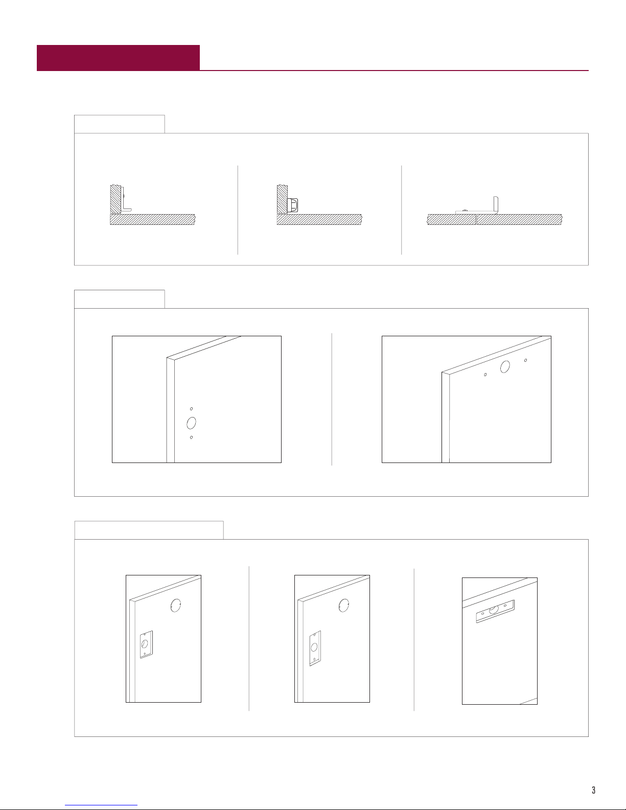
Before Lock Installation
3
The door must be prepared for lock installation.
1.
2a.
Strike Plate
Angled Strike Plate Security Strike Plate Double Door Strike Plate
Door Mounting Holes For surface mount installations, the door must have door mounting holes.
A strike plate must be installed.
2b.
For Standard & Vertical Body For Horizontal Body
Routed Door with Door Mounting Holes
For Standard Body For Vertical Body For Horizontal Body
For recess mount installations, the door must be routed and have door mounting holes.
Page 4
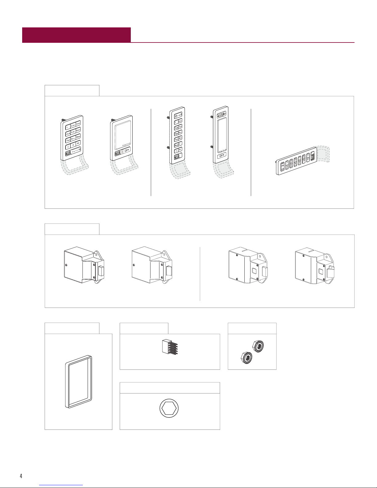
Surface Mount Installation
4
For door thickness measuring between .01” - .480” (0.01mm - 12.0mm)
Required Components
1 - Front Unit
Standard Body Keypad Vertical Body KeypadStandard Body RFID Vertical Body RFID Horizontal Body Keypad
1 - Rear Unit
1 - Plastic Ring
Springbolt Springlatch Deadbolt Deadlatch
1* - Pin Extender
*Required for door thickness measuring between
1* - Ratchet/Screw Gun with a 3/8” Socket
.315”-.480” (8.0-12.2mm)
1 - Locking Nuts
*Not included
u Do not use an electric screw gun unless it is equipped with a torque adjuster and is set to low.
Page 5

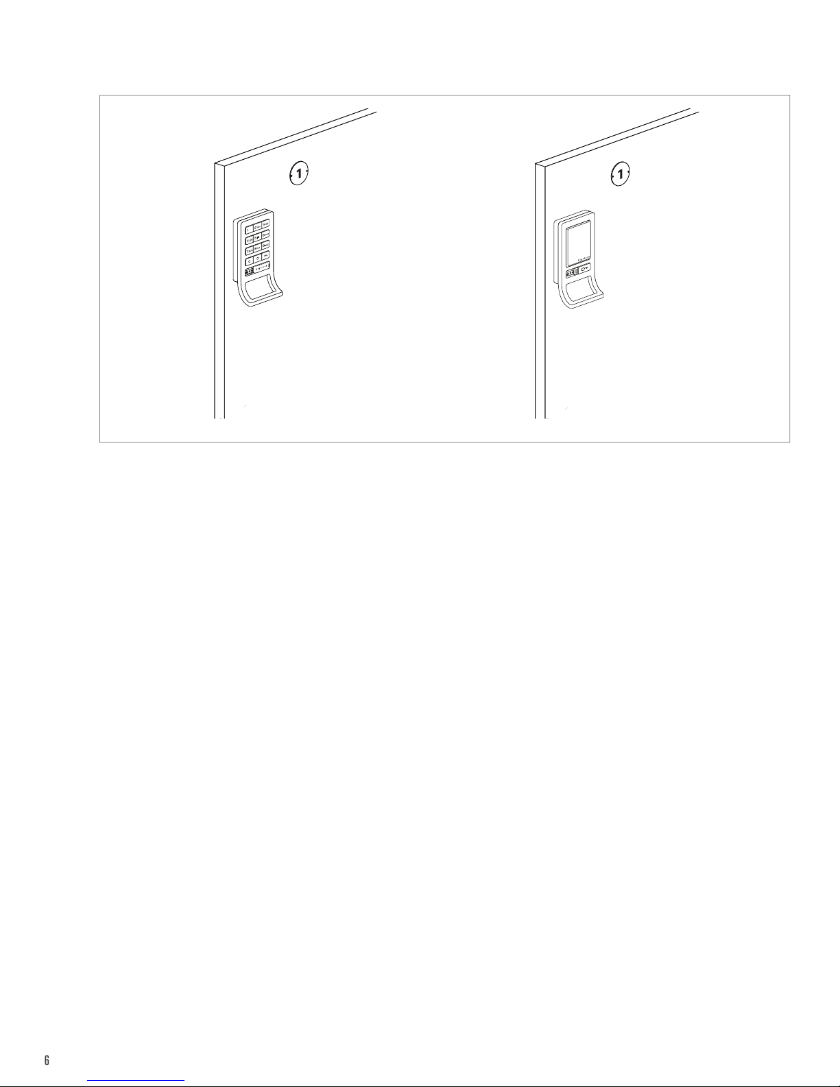
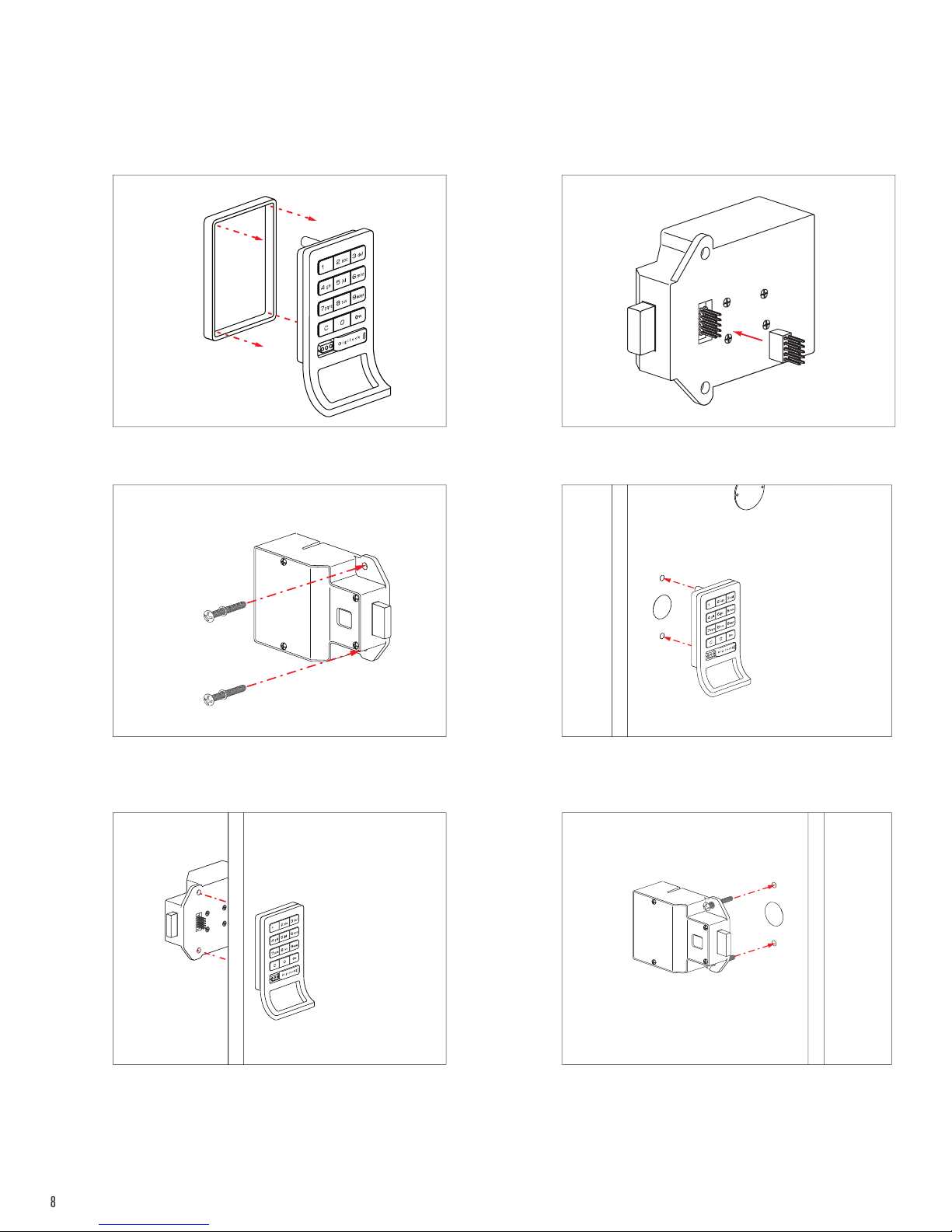
Installation
5
For illustration, a standard body, keypad lock with a bolt rear unit is used.
1 2
Place the plastic ring on the front unit. If required, connect the pin extender to the rear unit.
3
Insert the front unit screw posts through the door
mounting holes.
5
4
Hold the front unit against the front of the door. Use
the rear unit mounting holes as a guide, then slide the
front and rear units together.
6
Make sure the connector pins align properly with the
connector.
If properly connected, a triple beep will be heard and
the LED will flash three times.
Insert the locking nuts on the screw posts and tighten
using the ratchet/screw gun.
u Do not over tighten.
Page 6
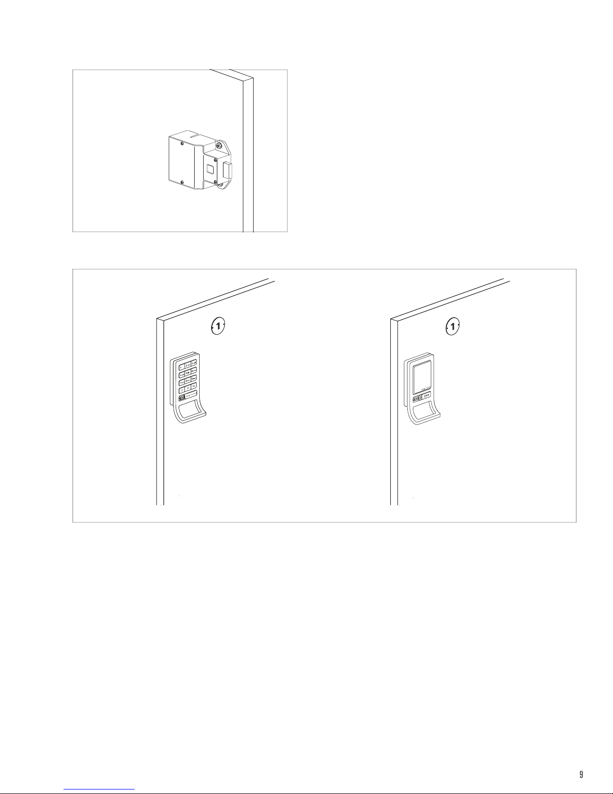
6
7
To test keypad locks: Press = ` To test RFID locks: Press `
Test the locks while the door is open. If locks do not operate, remove and reinstall.
Close the door and test again. If 10 rapid beeps are heard and the LED flashes 10 times, the strike plate and/or the door needs to
be adjusted as it is preventing the lock from operating.
Page 7
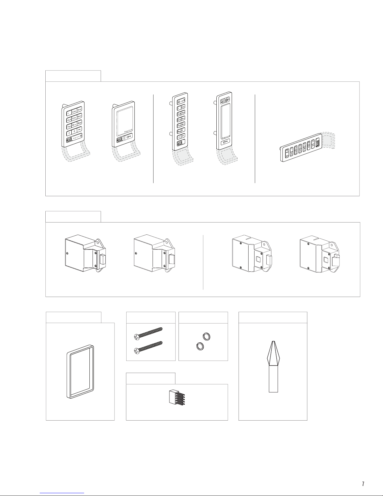
For door thickness measuring between .480” - 1.998” (12.2mm - 50.7mm)
7
Required Components
1 - Front Unit
Standard Body Keypad Vertical Body KeypadStandard Body RFID Vertical Body RFID Horizontal Body Keypad
1 - Rear Unit
Springbolt Springlatch Deadbolt Deadlatch
1 - Plastic Ring 2 - Phillips Head Screws
2 - Split Lock Washers 1* - Phillips Head Screwdriver (#2)
1* - Pin Extender
*Two (2) pin extenders are required for door thickness
measuring between 1.20”-1.998” (30.5-50.7mm)
u Do not use an electric screw gun unless it is equipped with a torque adjuster and is set to low.
*Not included
Page 8
Installation
8
For illustration, a standard body, keypad lock with a bolt rear unit is used.
1
Place the plastic ring on the front unit.
3
2
Connect the pin extender to the rear unit.
4
Place the split lock washers on the phillips head screws
and insert them through the rear unit mounting holes.
5
Hold the front unit against the front of the door. Use
the screws of the rear unit as a guide then slide the
front and rear units together.
Insert the front unit nut posts through the door mounting
holes.
6
Make sure the connector pins align properly with the
connector.
If properly connected, a triple beep will be heard and
the LED will flash three times.
Page 9
9
7
Tighten the screws using the phillips head screw driver.
8
To test keypad locks: Press = ` To test RFID locks: Press `
Test the locks while the door is open. If locks do not operate, remove and reinstall.
Close the door and test again. If 10 rapid beeps are heard and the LED flashes 10 times, the strike plate and/or the door needs to
be adjusted as it is preventing the lock from operating.
Page 10

Recess Mount Installation
10
For door thickness measuring between .370” - .850” (9.4mm - 21.6mm)
Required Components
1 - Front Unit
Standard Body Keypad Vertical Body KeypadStandard Body RFID Vertical Body RFID Horizontal Body Keypad
1 - Rear Unit
Solenoid Spring Bolt Solenoid Spring Latch Motorized Dead Bolt Motorized Dead Latch
1* - Pin Extender
*Required for door thickness measuring between
.685”-.850” (17.4-21.6mm)
u Do not use an electric screw gun unless it is equipped with a torque adjuster and is set to low.
*Not included
2 - Locking Nuts1* - Ratchet/Screw Gun with a 3/8” Socket
Page 11

Installation
11
For illustration, a standard body, keypad lock with a bolt rear unit is used.
1
If required, connect the pin extender to the rear unit. Insert the front unit screw posts through the door
3
2
mounting holes.
4
Hold the front unit against the front of the door. Use the
screws of the rear unit as a guide then slide the front
and rear units together.
5
Insert the locking nuts on the screw posts and tighten
using the ratchet/screw gun.
u Do not over tighten.
Make sure the connector pins align properly with the
connector.
If properly connected, a triple beep will be heard and
the LED will flash three times.
Page 12

12
6
To test keypad locks: Press = ` To test RFID locks: Press `
Test the locks while the door is open. If locks do not operate, remove and reinstall.
Close the door and test again. If 10 rapid beeps are heard and the LED flashes 10 times, the strike plate and/or the door needs to
be adjusted as it is preventing the lock from operating.
Page 13

For door thickness measuring between .850” - 2.368” (21.6mm - 60.1mm)
13
Required Components
1 - Front Unit
Standard Body Keypad Vertical Body KeypadStandard Body RFID Vertical Body RFID Horizontal Body Keypad
1 - Rear Unit
Solenoid Spring Bolt Solenoid Spring Latch Motorized Dead Bolt Motorized Dead Latch
1* - Phillips Head Screwdriver (#2) 1* - Pin Extender
*Two (2) pin extenders are required for door thickness
measuring between 1.570”-2.368” (39.9-60.1mm)
2 - Phillips Head Screws 2 - Split Lock Washers
*Not included
u Do not use an electric screw gun unless it is equipped with a torque adjuster and is set to low.
Page 14

Installation
14
For illustration, a standard body, keypad lock with a bolt rear unit is used.
1
Connect the pin extender to the rear unit. Place the split lock washers on the phillips head screws
3
2
and insert them through the rear unit mounting holes.
4
Insert the front unit nut posts through the door mounting
holes.
5
Make sure the connector pins align properly with the
connector.
If properly connected, a triple beep will be heard and
the LED will flash three times.
Hold the front unit against the front of the door. Use
the screws of the rear unit as a guide then slide the
front and rear units together.
6
Tighten the screws using the phillips head screw driver.
Do not over tighten.
Page 15

15
7
To test keypad locks: Press = ` To test RFID locks: Press `
Test the locks while the door is open. If locks do not operate, remove and reinstall.
Close the door and test again. If 10 rapid beeps are heard and the LED flashes 10 times, the strike plate and/or the door needs to
be adjusted as it is preventing the lock from operating.
Page 16

Door Preparation
16
Strike Plate Installation
Required Components
Strike Plate
1. A strike plate must be installed.
Angled Strike Plate Security Strike Plate Double Door Strike Plate
1* - Phillips Head Screwdriver (#1)
*Not included
Do not use an electric screw gun unless it is equipped with a torque adjuster and is set to low.
Page 17

Installation
17
1
Door Frame
Position the strike plate on the door frame centering
it with the center of the desired location of the door
mounting holes.
3
Drill Pilot
Holes Here
2
0.125 in
(3.18 mm)
Mark Here
Door Frame
Allow .125” (3.18mm) from door edge and mark the
position of the adjustment slot holes.
4
Door Frame
Drill 0.25” (6.35mm) pilot holes using a 1/6” drill bit.
5
0.125 in
(3.18 mm)
Door Frame
Door Frame
Position the strike plate and the self tapping screws into
the adjustment slot holes. Do not tighten the screws.
6
Door Frame
Adjust the strike plate to the proper position (.125”
(3.18mm) from the door edge) then tighten the self
tapping screws.
Position and tighten the remaining self tapping screw
into the center hole.
Page 18

Template
Center line
Strike
Plate
Center
Edge of Strike Plate
Strike Edge Marker
Mark
Template
Mark Door Edge
Template
Center line
Strike
Plate
Center
Edge of Strike Plate
Strike Edge Marker
Mark
Template
Mark Door Edge
Door Edge
Drawn
Marker
Template
Center line
Strike
Plate
Center
Edge of Strike Plate
Strike Edge Marker
Template
Center line
Strike
Plate
Center
Edge of Strike Plate
Strike Edge Marker
18
Door Mounting Holes Drill Instructions and Templates
Drill Instructions
For illustration, the mounting holes template for standard & vertical body locks is used.
1
Align both the center line and strike plate edge of the
installed strike plate.
Hold the template in place and close the door.
2
Mark
Template
Mark Door Edge
Mark the edge of the door on the template. Mark the
center line of the template on the edge of the door.
3
Door Edge
Drawn
Marker
Place the template on the front of the door.
Align the edge of the door with the mark on the template,
and then align the center line of the template with the
mark on the door.
Secure the template with removable tape.
4
Drill 3/4” - 0.75 in
(19.1 mm)
Drill x2
5/16” 0.3125 in
(7.94 mm)
Mark the center point of the three door mounting drill
holes on the front of the door.
Use the drill bits specified on the template to drill
appropriately sized door mounting holes.
Page 19

Template for Standard & Vertical Body
19
Templates may not print to scale. Check all measurements before proceeding.
Before printing, turn off auto scaling in printer setup and print at 100%.
All measurements in thousandths
ALIGN EDGE OF
STRIKE PLATE HERE
FOR LEFT
CLOSING DOOR
of an inch and millimeters
)mm( 9.72
001.1
.300
7.62 (mm)
use 5/16" bit
ALIGN EDGE OF
STRIKE PLATE HERE
FOR RIGHT
CLOSING DOOR
001.1
)mm( 9.72
CENTER LINE
CENTER LINE
ALIGN EDGE OF
STRIKE PLATE HERE
FOR LEFT
CLOSING DOOR
)mm( 9.72
001.1
.905
23 (mm)
.750
19.05 (mm)
use 3/4" bit
.300
7.62 (mm)
.905
23 (mm)
001.1
)mm(9.72
ALIGN EDGE OF
STRIKE PLATE HERE
FOR RIGHT
CLOSING DOOR
Page 20

Template for Horizontal Body
20
Templates may not print to scale. Check all measurements before proceeding.
Before printing, turn off auto scaling in printer setup and print at 100%.
CENTER LINE
ALIGN EDGE OF
STRIKE PLATE HERE
FOR TOP
CLOSING DRAWER
23 (mm)
.905
7.62 (mm)
.300
23 (mm)
.905
ALIGN EDGE OF
STRIKE PLATE HERE
FOR BOTTOM
CLOSING DRAWER
001.1
)mm( 9.72
19.05 (mm)
use 3/4" bit
.750
001.1
)mm( 9.72
ALIGN EDGE OF
STRIKE PLATE HERE
FOR TOP
CLOSING DRAWER
001.1
)mm( 9.72
use 5/16" bit
7.62 (mm)
.300
001.1
)mm(9.72
ALIGN EDGE OF
STRIKE PLATE HERE
FOR BOTTOM
CLOSING DRAWER
All measurements in thousandths
of an inch and millimeters
CENTER LINE
Page 21

Routing Instructions and Template
21
Routing Instructions
1. Choose the appropriate routing template (standard, vertical, or horizontal).
2. Drill the appropriate door mounting holes. Refer to the door mounting holes drill instructions and template.
3. Align the mounting holes drawn on the template with the mounting holes drilled on the door.
4. Route the door according to the measurements shown on the template.
Page 22

Routing Template for Standard Body
(
)
4x
22
Templates may not print to scale. Check all measurements before proceeding.
Before printing, turn off auto scaling in printer setup and print at 100%.
2.19 in
56 mm
)
.300 (8
.75 (19
mm
)
)
2.01 in (51 mm
1.98 in (50
)
mm
2x
)
mm
0.400/0.425 in DEEP
(
10/11
mm
)
2.72 in (69 mm
2.68 in (68
mm
R 0.125(3
)
)
mm
Page 23

Routing Template for Horizontal Body
)
)
.400/.425 DEEP
23
Templates may not print to scale. Check all measurements before proceeding.
Before printing, turn off auto scaling in printer setup and print at 100%.
(
10/11mm
R 0.125”
(
3mm
4x
0.75”
(
)
)
19mm
)
2.185” (56mm
3.80” (97mm
3.78” (96mm
0.30”
(
8mm
)
)
)
2x
)
1.25” (32mm
1.23” (31mm
Page 24

Routing Template for Vertical Body
)
R 0.125”
)
)
24
Templates may not print to scale. Check all measurements before proceeding.
Before printing, turn off auto scaling in printer setup and print at 100%.
1.25” (32mm
(
3mm
4x
)
1.23” (31mm
)
.400/.425 DEEP
(
10/11mm
0.30”
(
)
8mm
2x
3.80” (97mm
2.185” (56mm
0.75”
(
)
19mm
)
)
3.78” (96mm
Page 25

Metal Door Preparation
25
Compatibility Guide
Digilock is compatible with a majority of 3-hole configuration, latch, and handle door types. Some doors may require modification
to clear obstructions.
Single Point Latch
Handle
Standard Lift
Box Locker Padlock Hasp
Recessed Cup with Multi-point Latch
Recessed Cup with Single Point Latch
Page 26

Removal of 3-hole Lock Plug
26
Remove any obstructions to the door mounting holes.
Example 1Example 2
Rear View of
Locker Door
with Lock Plug
Rear View of
Locker Door
with Lock Plug
Front View of
Locker Door
with Lock Plug
Front View of
Locker Door
with Lock Plug
Page 27

Removal of Padlock Hasp
27
The padlock hasp must be removed
1 - Metal File1 - Handheld Grinder or Hack Saw
Close the door and make sure that
nothing is protruding above the
surface of the door.
Example 1Example 2
Open the door then cut the padlock
hasp on the marked cut-line.
Smooth out rough or sharp edges.
Close the door and mark the area to
cut the padlock hasp.
IG-XXXX-XX-DEN
071114
Phone: 707 766 6000
www.digilock.com | support@digilock.com
 Loading...