

Page 1

PULSE MX-EX
PROFESSIONAL LIGHT DESK
FOR UPDATE AND FIXTURE VISIT www.digilite.eu
USER MANUAL
English version
Rev. 03 -10/13
digilite.eu
Page 2

Page 3

TABLE OF CONTENTS
PULSE MX
3
Safety
General instructions
Warnings and installation precautions
General information
Introduction
Description
Technical specications
PART 1: QUICK-START GUIDE
1 Overview of the console
1. 1 Operating elements and connections
1. 2 Edit Keys
1. 3 Playback keys
1. 4 Controllers
1. 5 Grand Master and DBO
1. 6 Pan/Tilt pointing
1. 7 Encoder wheels
1. 8 Console setup
2 Create a new show
2. 1 Adding xtures to the library
2. 2 Fixture patch
2. 3 Editor
2. 4 Saving a cue
2. 5 Editing cue
2. 6 Palette
2. 7 Playing or transmitting a cue
2. 8 Store menu
PART 2: USER MANUAL
4
5
5
6
6
8
9
10
10
10
11
11
11
12
13
14
16
17
17
17
19
2. 3 Grand master and group masters gruppo
3 Cue list
3. 1 Qlist mode
3. 2 Chase mode
3. 3 Sequence mode
3. 4 Live mode
3. 5 Context-specic menu
4 Controllers
4. 1 Controller conguration
5 Setup
5. 1 Add Fixtures
5. 2 General Options
5. 3 Fixture conguration
5. 4 Controller conguration
5. 5 Pan/Tilt options
5. 6 Artnet conguration
5. 7 Backup/restore
5. 8 Library manager
5. 9 Diagnostic
5. 10 Fixture builder
6 SMPTE Timecode
7 MIDI Interface
8 DMX-IN Ingresso
9 Expansion
9. 1 Operating elements and connections
9. 2 Connection to the console
9. 3 How the expansion works
32
33
35
36
37
38
39
44
46
47
47
47
48
50
52
54
56
62
64
66
70
71
71
1 Editor
1. 1 Fixture display
1. 2 Group display
1. 3 Palette display
1. 4 Predened palettes
1. 5 Context-specic menu
1. 6 Fan
1. 7 Eects
1. 8 Color picker
2 Playback
2. 1 Cue input
2. 2 Controllers input
20
22
22
24
24
26
27
29
30
31
10 Appendix
10. 1 Glossary
Warranty
Packing content:
• PULSE MIXER
• Main cable
• USB keys
• User manual
72
Page 4

4
WARNING! Before carrying out any operations with the unit, carefully read this instruction
manual and keep it with cure for future reference. It contains important information about
the installation, usage and maintenance of the unit.
NOTE
This manual is divided into two parts: the Quick-Start Guide, which gives a general overview of the console and enables the operator to be immediately operational using the basic functions. The second part
is the actual user manual where many of the concepts seen in the rst part are examined in greater detail.
It is recommended that you rst read the Quick-Start Guide in order to have a global overview of the
console's features and settings and to be able to contextualize the information in the second part more
accurately.
PULSE MX
SAFETY
General instruction
• The products referred to in this manual conform to the European Community Directives and are
therefore marked with .
• The unit is supplied with hazardous network voltage (230V~). Leave servicing to skilled personnel
only. Never make any modications on the unit not described in this instruction manual, otherwise
you will risk an electric shock.
• Connection must be made to a power supply system tted with ecient earthing (Class I appliance
according to standard EN 60598-1). It is, moreover, recommended to protect the supply lines of the
units from indirect contact and/or shorting to earth by using appropriately sized residual current
devices.
• The connection to the main network of electric distribution must be carried out by a qualied electrical installer. Check that the main frequency and voltage correspond to those for which the unit is
designed as given on the electrical data label.
• This unit is not for home use, only professional applications.
• Never use the xture under the following conditions:
- in places subject to vibrations or bumps;
- in places with a temperature of over 45 °C or lower than 2°C.
• Make certain that no inammable liquids, water or metal objects enter the xture.
• Do not dismantle or modify the xture.
• All work must always be carried out by qualied technical personnel. Contact the nearest sales point
for an inspection or contact the manufacturer directly.
• If the unit is to be put out of operation denitively, take it to a local recycling
plant for a disposal which is not harmful to the environment.
Page 5

PULSE MX
5
Warnings and installation precautions
• The unit for indoor use only. To prevent or reduce the risk of electrical shock or re, do not expose the
unit to rain or moisture.
• If this device will be operated in any way dierent to the one described in this manual, it may suer
damage and the guarantee becomes void. Furthermore, any other operation may lead to dangers like
short circuit, burns, electric shock, etc.
• When carrying out any work, always comply scrupulously with all the regulations (particularly regarding safety) currently in force in the country in which the xture’s being used.
• Keep any inammable material at a safe distance from the xture.
• Before starting any maintenance work or cleaning the xture, cut o power from the main supply.
GENERAL INFORMATION
Warranty and returns
The guarantee covers the xture in compliance with existing regulations. You can nd the full version of
the “General Guarantee Conditions” on our web site www.digilite.eu
All rights reserved by Digilite No part of this instruction manual may be
reproduced in any form or by any means for any commercial use.
In order to improve the quality of products, Digilite reserves the right to modify the characteristics stated in
All revisions and updates are available in the ‘manuals’ section on site www.digilite.eu
this instruction manual at any time and without prior notice.
Page 6

6
PULSE MX
INTRODUCTION
PULSE MX
DESCRIPTION
PULSE-MX is a professional lighting console by DIGILITE featuring a familiar and exible GUI interface,
ideal for controlling large and small lighting systems. PULSE-MX has been designed to be easily transportable and compact in its sizes, without the need of external monitors or control hardware for the
setup and programming. The large integrated touch-screen LCD color display and linear fader displays
make additional external monitors unnecessary, every control are at your ngertips. PULSE-MX can
support up to 3072 DMX channels, 2 independent direct output and 4 universes over ArtNet, and all
programming operations are executed through 4 encoder wheels (for controlling the parameters of Palettes during editing or for assigning values in programs), one JogBall for Pan/Tilt control (with Fine and
Lock control), Grand Master fader and DBO. Playback section is composed by 12 programmable control
buttons and faders (playback master, master group, manual cue) and 24 playback keys, which can be
expandable with 24 extra controllers and 48 playback keys with 2 PULSE-EX playback wings. PULSE-MX
is a versatile and multi-purpose console, ideal for rental companies and professionals who are in search
of a high-performance work tool, with compact sizes and fast/easy programming, which can be used in
almost all events.
TECHNICAL SPECIFICATIONS
Controls
• 7’’ 800x480 pixel touchscreen TFT LCD color display
• 2 backlit LCD display with 72 characters (2 lines x 36 digits) to show the fader congurations
• 12 controllers buttons for direct access to playback and programming functions
• 12 faders with key buttons individually congurable as Playback master, Group master, Manual Cue
• 24 keys for direct access to playback registers
• 4 Encoder wheels to control the features and eects during programming
• Jog Ball for Pan and Tilt control with Lock and Fine resolution buttons
• GrandMaster fader and DBO button
• Internal memory with SD slot
Performance
• Powerful GUI interface able to easily manage the programming and playback up to 576 Cue-lists (organized in 24 pages with 24 cue-list each), each having a maximum of 999 cues
• 3072 DMX channels: 2 direct univere DMX OUT through XLR 3p e 5p, 4 universes over Art-Net ethernet, 1 DMX IN line (independent)
• Playback up to 48 simultaneous cue-lists
• Advanced eect generator
• Updatable personalities library
• 6 genres of programmable palettes for a quick and exible programming of moving projectors
• Pre-programmed Chris/Gam/Lee/Rosco palettes for use on all xtures with RGB or CMY color mixing
• Maximum number of cues per show: 9999
• 1 Flexible LED light
• Universal switching power supply: 85-265 Volt
• Internal processor 454 Mhz with 128Mb RAM
• Internal 4Gb SD memory card to store libraries, cues and data
Page 7
PULSE MX
Connections
• DMX out: 2 x XLR-3p; 2x XLR-5p; 1x RJ45 Art-net
• DMX in: 1 x XLR-5p
• SMPTE in: 1x XLR-3p
• MIDI in/out/thru: DIN-3p
• Backup and memory: USB port
• Service light: 1x USB port
• PULSE-EX wings: 2x RJ12
Dimensions and weight
• Net weight: 12 kg
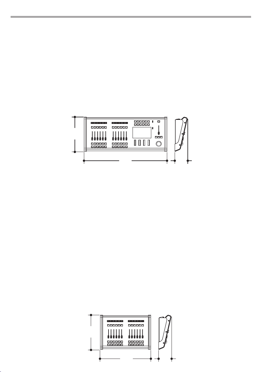
• Dimensions: 692x288x105 mm
288
7
692
105
PULSE EX
DESCRIPTION
PULSE-EX is a playback wing for PULSE-MX DIGILITE console, conceived to oer a wider surface of available controls. The playback wing PULSE-EX is composed by 12 programmable fader, 12 control buttons
and 24 playback key. PULSE-EX connects to PULSE-MX via cable, no extra software required, just connect
the Wing to the console and the Playbacks are ready to control your show.
TECHNICAL SPECIFICATIONS
• 2 backlit LCD display with 72 characters (2 lines x 36 digits) to show the fader congurations
• 12 controllers buttons for direct access to playback and programming functions
• 12 faders with key buttons individually congurable as Playback master, Group master, Manual Cue
• 24 keys for direct access to playback registers
• Power supply directly from PULSE-MX
• Weight: 5kgs
288
422
105
Page 8
8
PULSE MX
PART 1: QUICK-START GUIDE
- 1 - OVERVIEW OF THE CONSOLE
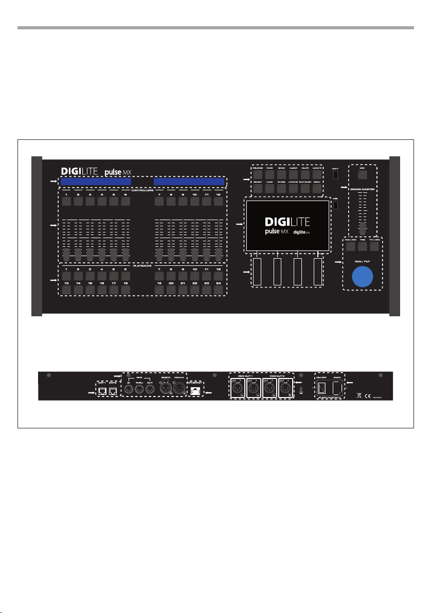
1.1 OPERATING ELEMENTS AND CONNECTIONS
1
2
3
Front panel
Rear panel
4
7
5
8
6
10
9
1. CONTROLLER STATUS
2. CONFIGURABLE CONTROLLERS
3. PLAYBACKS
4. EDIT KEYS
5. MAIN TOUCHSCREEN
6. ENCODER WHEELS
7. GRAND MASTER E DBO
8. PAN & TILT POINTINGS
9. EXPANSION CONNECTOR 1 AND 2
10. MIDI, SMPTE AND DMX-IN SOCKETS
11. ARTNET OUTPUT 6 UNIVERSES
12. DMX OUTPUT UNIVERSE 1 AND 2
13. POWER SOCKET WITH SWITCH
11
12
13
Fig.1
Page 9

PULSE MX
1.2 EDIT KEYS
Release
Used to interrupt:
• a single playback (Release + playback key)
• a single controller (Release + ash controller key)
• all playbacks (Release + Page)
• all controllers (Release + Bank)
• all registers and all controllers (double click on the key releases in quick succession)
Page
Used to select a new playback page; the console manages 24 pages each of which contains 24 cue
lists. To select a new page, simultaneously press the Page key and playback key corresponding to
the new desired page (or press these two keys in quick succession). Press the Page key twice in quick
succession to go to the next page.
Bank
Used to select a new controller bank; the console manages 24 ‘banks’ each of which contains up to
12 controllers (depending on the conguration of the console). To select a new bank, press Bank +
the playback key corresponding to the new desired bank (or press the two mentioned keys in quick
succession). Press the Bank key twice in quick succession to go to the next bank.
Clear
Pressing once only erases the contents of the editor limited to the selected xtures; pressing twice in
quick succession erases the entire content of the editor and unchecks all xtures (“Clear all” function)
9
Hilite
Two-state key, alternatively activates and deactivates the hilite status. When the hilite is active, the
Hilite palette, which usually opens the shutter and sets the dimmer at 100%, is forced in the xtures
selected in the editor. The hilite is typically used to create a cue without dimmer information; in fact,
the operator can see the xture’s behaviour, but such information is not inserted into the editor and
therefore is not saved in the cue.
Locate
Apply the Locate palette to the selected xtures; it denes a denitive status for all cue parameters
(typically dimmer = 100%, pan & tilt = 50%, wheel color = white, etc.). Normally used before starting
to program a series of cues.
Select
Used to display the current playback or select a new playback.
By pressing the Select key, the current playback LED turns on; if while the LED is turned on you press
the new playback key, this playback becomes the current new playback. You can also select a current new playback by pressing the Select key and the playback key in quick succession. Selecting
the current playback also occurs when pressing a playback key to transmit a cue; the selected key is
therefore used to change the current playback without transmitting any further cue.
Pressing the select key twice in quick succession selects the next playback.
Page 10

10
Load
Used to load a cue or a palette into the editor for any amendments. The Load key loads the last cue or
palette selected into the editor or, if pressed simultaneously with the ash key of a controller, it loads
the controller cue into the editor (only if the controller is congured in ‘manual cue’).
Store
Activates the Store menu. When the store menu is active, it is possible to save a palette (yellow buttons), a cue (brown buttons) or save the currently selected xtures as a new group.
If a controller is congured in manual cue, by simultaneously pressing the Store key and its ash key,
the contents in the editor are saved in the cue associated with the controller itself.
Pressing the Store key twice in quick succession saves the contents of the editor as a new cue in the
current playback.
Update
Updates and saves the last cue or palettes loaded into the editor. During loading, the console keeps
track of the amount loaded into the editor; the Update key overwrites the original cue or palette with
the current contents of the editor.
Edit/Qlist
Key that alternately recalls the windows of the editor and cue lists.
Menu
Activates a pop-up menu that allows access to auxiliary functions of a particular window. In each
window, for reasons of space or opportunity, less frequently used functions are placed in the context
specic menu.
PULSE MX
1.3 PLAYBACK KEYS
When you press a playback key, it activates the rst cue on the cue-list contained in the playback, or
activates the next cue, if the cue list was already active (“Go” function); this last playback also becomes
the current registry playback.
Can be used in conjunction with the Release Select, Page and Bank keys (see Edit Keys section).
1.4 CONTROLLERS
The controllers can be individually congured in three dierent ways: Playback master, manual cue or
group master. Conguration of the controllers is carried out by means of the Controller conguration
window retrievable from the Setup menu (see Chap. 4 — Controllers.); the default value (after a Clear
show) is Playback master.
1.5 GRAND MASTER AND DBO
The grand master slider only regulates the level of the console HTP channels (usually the channels that
regulate the brightness of the xtures);
Pressing the DBO key (Dead Blackout) will immediately force all HTP channel levels to zero and these will
remain at zero as long as the key is pressed.
Page 11

PULSE MX
1.6 PAN/TILT POINTING
For all pan and tilt pointing, the console features a 38 mm trackball and three keys: Pan lock, Tilt lock
and Fine. The Pan lock and Tilt lock keys are two-state keys which allow to respectively lock the pan and
tilt movements while the Fine key is a three-state key that, when repeatedly pressed, activates three
dierent types of trackball sensitivity: 8, 12 and 16 bits. The Fine key aects the behavior of the encoder
wheels too.
1.7 ENCODER WHEELS
Encoder wheels are used dierently depending on which windows are active, but their main use is to
change values or scroll to lists of names and/or objects. On a case by case basis, on the graphic screen in
correspondence of each wheel, the function completed by the wheel itself will be indicated.
1.8 CONSOLE SETUP
The setup of the console is very easy and consists of the following points:
• Plug the power cable into the corresponding socket. The console can be supplied with a voltage between 90 and 260 volts at a frequency of between 40 to 60 Hertz.
• Connect the DMX outputs to the xtures or, alternately, the Artnet output to an Artnet/DMX converter; in the case of the latter, enable the Artnet output (see Cap. 5—Setup, Artnet paragraph).
• Connect any expansion units
• Turn on the power switch located on the rear panel of the console
IMPORTANT: Each DMX output foresees two xlr connectors, one 5 pin and one 3 pin, that are internally
connected in parallel. Connect the xtures to only one of these two connectors; do not use both otherwise a
mismatching of impedances may occur, leading to a malfunction of the DMX.
11
Page 12
12
PULSE MX
- 2 - CREATE A NEW SHOW
The creation of a new show requires a conguration phase in which the console is congured with all
the settings, and more importantly the number and type of xtures involved in the show are set on the
console.
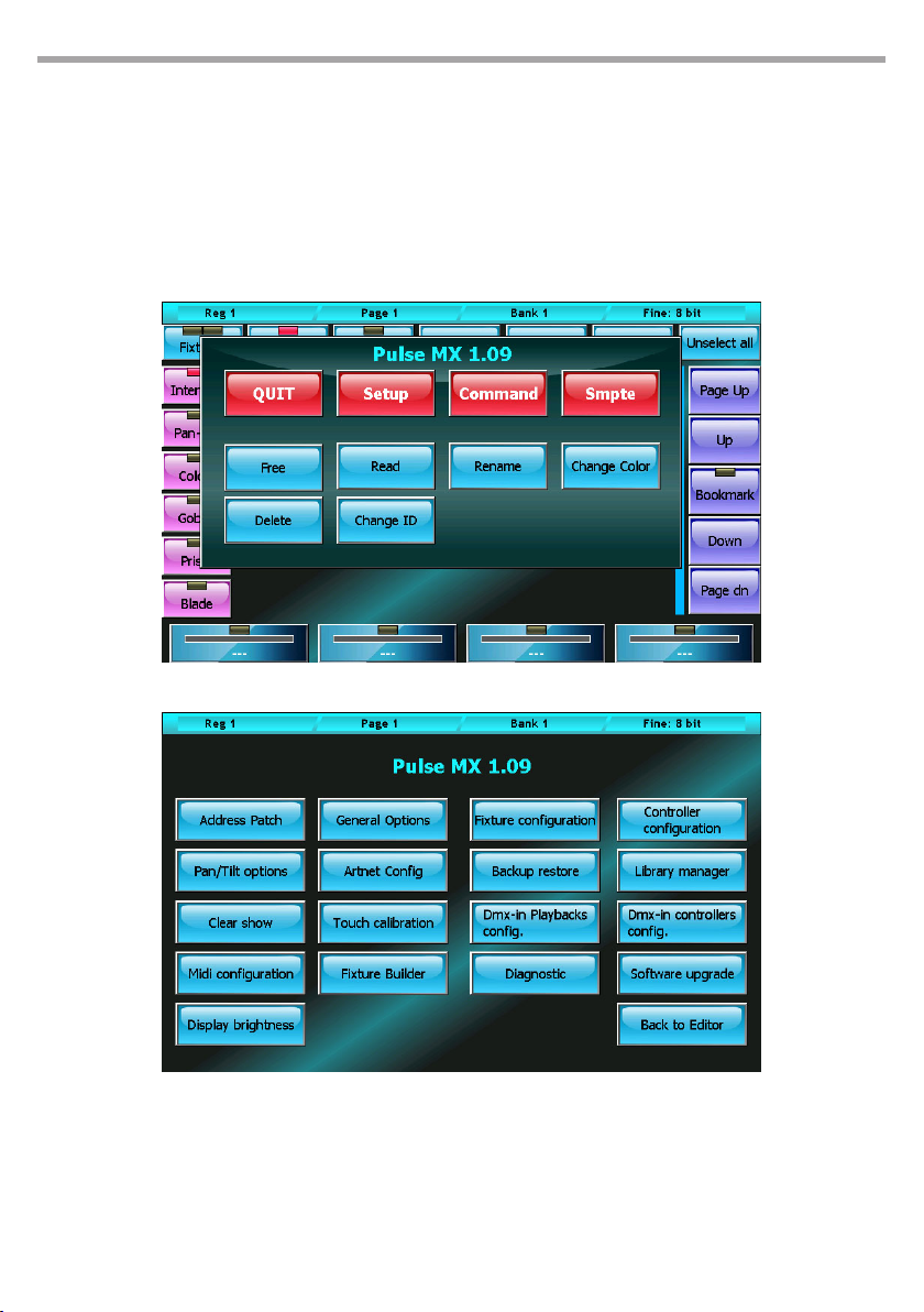
All these operations are accessible from the Setup menu which in turn can easily be recalled by pressing
the Menu key and selecting the Setup button (located on the context-specic menu).
Fig.2Context-specic menu
Fig.3Setup menu
2.1 ADDING FIXTURES TO THE LIBRARY
The console uses FDF les (xture denition les) or Pilot 3000 FXR les as it is fully compatible with the
latter.
To import fdf (or fxr) les into the console, use a normal USB drive: on the USB, create an FDFLIB folder
which will contain the folders of the brands which contain fdf les; then, place the USB in the USB port
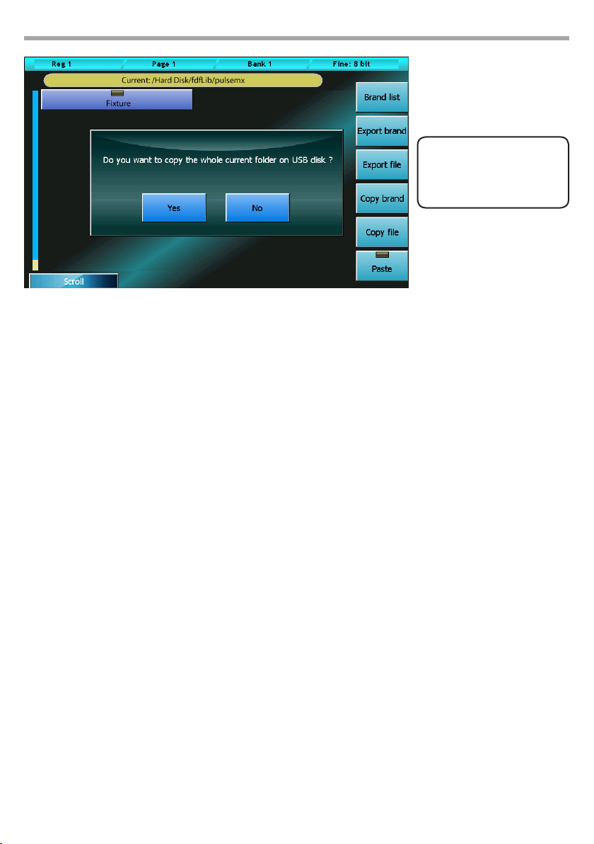
of the console and, using the Library manager (Setup menu), import/copy single les or entire folders.
Page 13
PULSE MX
13
THE FIXTURE PROFILES
CAN BE DOWNLOADED
FROM THE WEB SITE AT
www.digilite.eu
Importing a xture into the console library
For example: importing a FIXTURE Ex.fxr le
Supposing the USB memory is recognised as a disk G: of our PC
1. We create the G:\FDFLIB folder and then a G:\FDFLIB\BRAND folder; we then copy the FIXTURE.fxr le
into the G:\FDFLIB\BRAND we have just created.
2. We place the USB drive into the USB port of the console, press the Menu key to recall the Setup menu
and select Library manager.
3. From the Library manager, we press the Menu key and then USB disk: all the folders available in FDFLIB will be displayed; by pressing the BRAND button, all existing les in the \FDFLIB\BRAND folder
will be displayed
4. We select our xture by pressing the BRAND button and then again on the FIXTURE. fxr button; the
LED of the FIXTURE button will turn red to conrm the selection.
5. We press the Import button and conrm. In this way, by going back to the internal disk (Internal disk
button of the context-specic menu) we will nd the new FIXTURE xture in the BRAND.
2.2 FIXTURES PATCH
This window enables you to tell the console which and how many xtures are involved in the show and
the information related to their DMX addressing.
Pressing the Address Patch button from the Setup Menu activates the patch window. This window is
divided into two sections: the left section allows us to navigate in the xtures library, while the right section show the xtures which have already been added to the show enabling us to edit them.
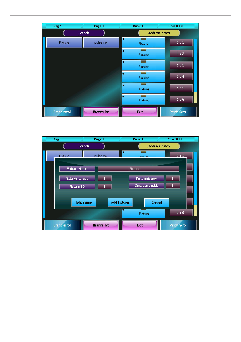
For example, if we wanted to add 8 identical xtures, connected to the DMX 2 line and mapped next to
one another starting from the DMX 120 addressing, we would rst have to select the BRAND button on
the left-hand side of the window and then the FIXTURE button; the Add xtures window will appear and,
using the encoder wheels, we will set 8 in the Fixtures to add eld, 2 in the DMX universe eld and 120
in the DMX start add eld; nally, we will have to conrm the data by pressing the Add xtures button.
Fig.4
Once this has been completed, the Add xtures window disappears and the right-hand side of the Address patch window is populated with 8 buttons, one for each xture added.
Page 14
14
PULSE MX
(Add xtures window)
2.3 EDITOR
The console manages 24 pages of 24 playbacks, each of which contains a cue-list which in turn can be
made up of, in the simplest of cases, one single cue, or a maximum of 999 cues.
To create or edit a cue, use the editor window (or simply editor); the editor allows you to control all attributes of all xtures of the show and save their values as playback cues, manual cues or palettes.
To edit a parameter of one or more xtures, rst select them by pressing the buttons of the xtures involved (editor in xture mode) or by pressing the group buttons (editor in group mode); then with the
buttons on the left select the family of attributes you wish to edit and nally, using the wheels, set the
values.
To set the value of a previously set attribute to Empty, click on the button of the wheel which controls it.
The trackball is always active on the pan and tilt of the selected xtures.
Values can be conveniently set by using the palettes instead of the wheel and trackball (see Palette paragraph). In this case, programming the cue is limited to selecting the xtures (single or in groups) and to
selecting the various palettes to use (position, colors, gobo, etc.)
Fig.5Inserting new xtures in the show
Fig.6Address patch window
Page 15
PULSE MX
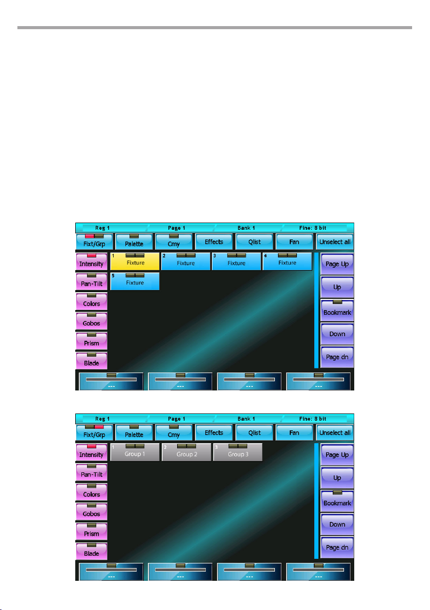
Each button of the xtures and groups has two “leds”: the left LED shows the status of the xture parameters:
• Green: all xture/group parameters are under the editor’s control,
• Orange: not all xture/group parameters are under the editor’s control,
• O: the editor does not control any parameter.
The right LED indicates whether the xture/group is selected or not. In the case of the groups, it can also
turn yellow to indicate that the group has been partially selected.
By pressing the Fixt/Grp button, you switch from xture to group display and vice versa.
The Clear key deletes all editor content of the selected xtures. Pressing the same key twice in quick succession deletes ALL editor content.
The wheels enable you to set or edit the attribute values of the selected xtures. The left buttons (Intensity, Colors, ...) allow you to scroll through the attributes which are controlled by the wheels.
The trackball is always active on the pan and tilt of the selected xtures.
15
Editor: xture display mode Fig.7
Fig.8Editor: group display mode
Page 16

16
2.4 SAVING A CUE
When you want to save a new cue, press the Store key to activate the Store menu and then select the
Cue button; doing this will add a new cue to the current playback in which the contents of the editor
will be copied.
WARNING: normally the programming of a cue begins by selecting the xtures involved and pressing the
Locate key in order to set all the xture attributes to a dened value. Only in advanced use for expert users it is
possible to program the cues by leaving Empty attribute
Press the Qlist button at the top of the editor to activate the cue-list window.
By selecting one or more cues and moving the encoder wheels it is possible to modify the Delay, Fadein, Wait and Fade-out times of each cue; if you omit the Wait and Fade-out times, the cue continues to
control the channels until a second cue intervenes or the Release playback is performed.
PULSE MX
Menu store (1=store palette, 2=store cue) Fig.9
Fig.10Cue-list window
Page 17

PULSE MX
2.5 EDITING A CUE
From the cue-list display windows (Qlist, Chase, Sequence or Live windows), select the cue you wish to
edit and press the Load key; in this way, a copy of the cue in question is loaded into the editor. Thanks
to the editor, it is now very easy to perform the required editing tasks. Finally, press the Update key to
substitute the original cue.
2.6 PALETTE
Palettes are predened memories which speed up programming; each xture usually already has some
predened palettes in the fdf le, but the user can create new personalised ones. The preparation of pantilt palettes is very useful in that, once having nished preparing the palettes, xture pointing is done
by simply by selecting the xtures concerned and then clicking on the palette of the desired location.
IMPORTANT: it is useful to program a show by using the palettes, because the time spent preparing the palettes
is recovered with interest during the programming phase which entails selecting the xtures (individual or in
groups), and various palettes to use (positions, colors, gobo, etc.)
To recall the palette window, simply press the Palette button located at the top in the editor.
To save a new palette bring up the Store menu by pressing the Menu key and then select one of the yellow buttons relating to the ‘family’ of values that we want to save; in fact when saving a palette, not all
the content in the editor is saved, but only the parameter values that belong to the same family of the
button pressed.
The palettes, like the parameters of the xtures, are organized into 6 families: Intensity, Pan/tilt, Colors,
Gobos, Prism and Blade; the palettes displayed in the window are those relating to the current family
(which can be changed by pressing the buttons on the left of the screen) and ONLY those relating to the
selected xtures. In the case that no xture is selected, all xtures of the current family are displayed.
17
The console also contains 4 sets of default palettes (Chris, Gam, Lee and Rosco) usable on all xtures that
have RGB or CMY color mixing systems. The current set can be selected in the General options window
accessible from the Setup menu.
2.7 PLAYING OR TRANSMITTING A CUE
To activate a cue, just press the corresponding playback key. Once the playback key is pressed, the following cue is activated (once the last one is reached, it starts again from the rst one.)
The intensity master is set at 100% with the exception of playbacks which have controllers congured as
playback masters, in which case the slider becomes the intensity master.
When two cues belonging to two dierent playbacks clash on a same channel, the console applies the
following criteria:
• if the channel is LTP, the LTP criteria is always applied (the most recently activated cue has priority)
• if the channel is HTP, the LTP or HTP criteria is applied (the highest values appears) as specied in the
Playback mode eld of the General options page (Setup Menu)
You can productively choose the Live window to transmit cues without a predened order.
ATTENTION: The editor has priority over the playbacks, therefore ensure it is not checking any xtures prior to
transmitting a cue. To reset the editor, press the Clear key twice in quick succession.
Page 18
18
PULSE MX
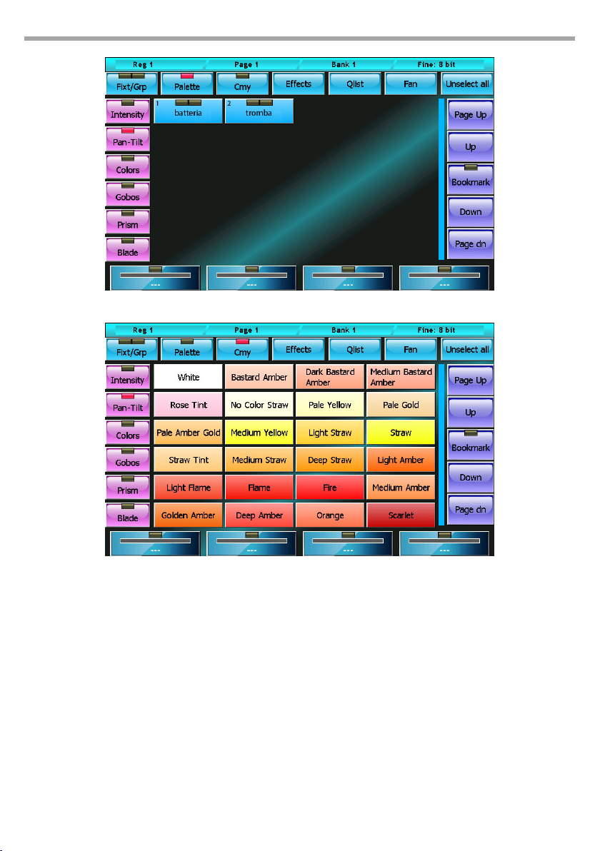
Pan/tilt palette window
Predened Rosco palettes
To ‘turn o’ a playback, press the Release key and the playback key in quick succession (before the LED of
the Release key switches o) or alternatively press and hold the Release key while pressing the playback
key. This action puts all projectors involved by the cue to Stand-By mode (dened by the Stand-by values
in the xture conguration window); the dimmer is typically reset to 0, while the remaining channels
stay set the way they are.
Fig.11
Fig.12
Page 19
PULSE MX
2.8 STORE MENU
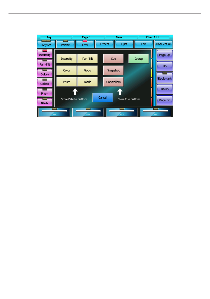
The Store menu, which is activated by pressing the Store key, enables you to save dierent types of objects:
Menu store Fig.13
BUTTONS
Intensity, Pan-Tilt, Color, Gobo, Prism and Blade
Save the editor content, limited to the selected type of parameters, in a new corresponding palette.
19
Cue
saves the editor content, adding it as new cue into the current playback
Snapshot
Saves the status of the channels controlled by the Editor, Playbacks and Controllers by adding it like
a new cue to the current playback
Controllers
Saves the status of the channels controlled by the Controllers, adding it like a new cue to the current
playback
Group
Creates a new group containing the selected xtures
Page 20
20
PULSE MX
PART 2: USER MANUAL
- 1 - EDITOR
The editor is the programme which enables you to set (and edit) the values of all parameters of the xtures and to save their status as a cue or palette.
The editor has various windows and displays; when switched on, the console shows the editor in display
xtures mode.
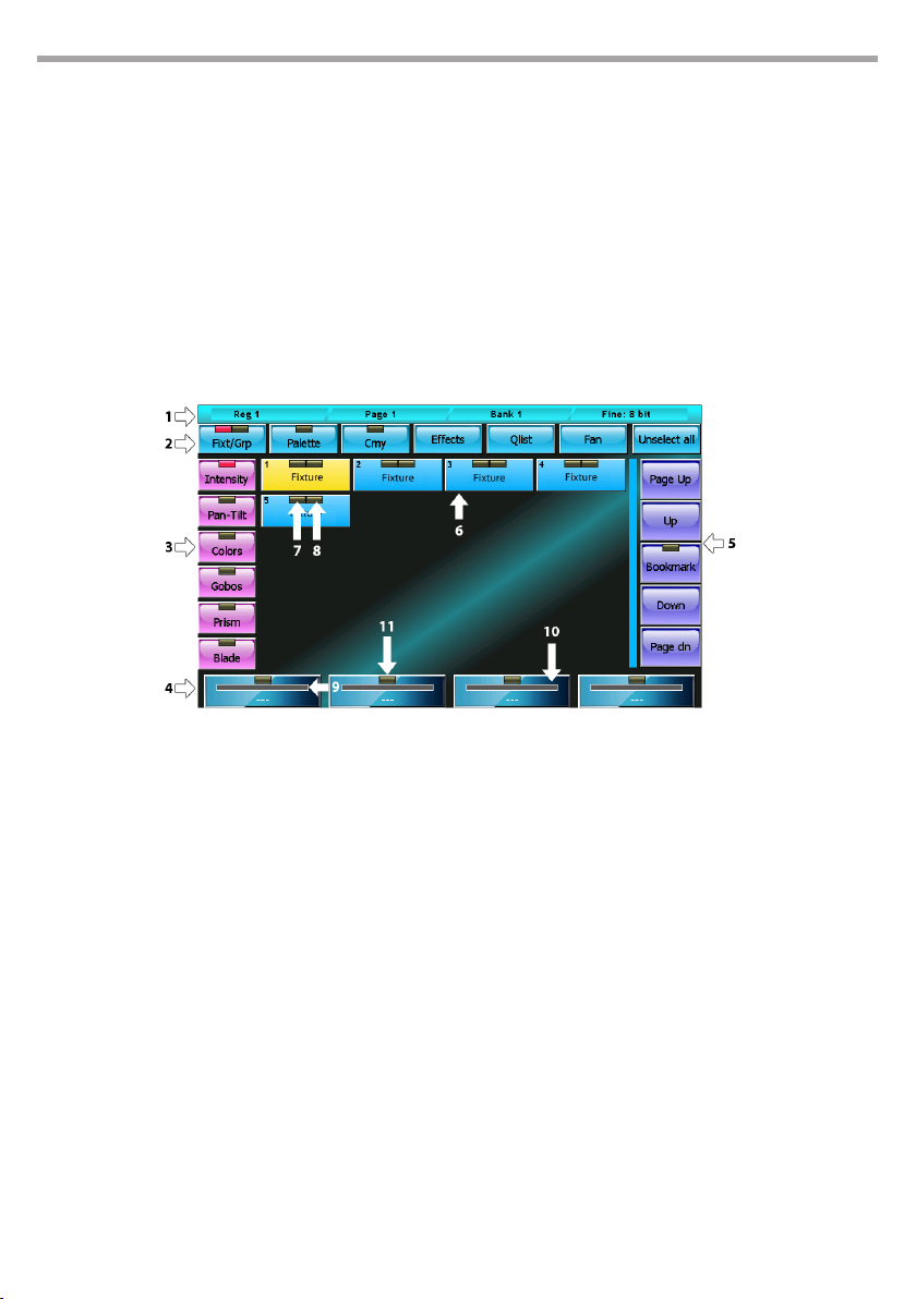
1.1 FIXTURES DISPLAY
Fixture display editor mode
Window contents
1 – status bar
From left to right: Current playback, Current page and Current Bank.
2 – command buttons
Each of these buttons carries out a specic command or opens a dierent window:
• Fixt/Grp: Switches between Fixture display and Group display
• Palette: recalls the Palette display
• Cmy: Recalls the default palette window which can be used on all xtures with RGB or CMY color
mixing systems
• Eects: Recalls the Eects window
• Fan: Recalls the Fan window
• Unselect All: Deselects all selected xtures
3 – parameter selection buttons
Pressing one of these buttons, the 4 parameters of the corresponding family, limited to selected
xtures, are displayed on the wheels and can be edited. If the selected family has more than 4 parameters, press the button again to scroll through them all, 4 at a time.
Fig.14
Page 21

PULSE MX
4 – Wheel buttons
Each wheel is associated with the parameter displayed on the corresponding button relating to all
selected xtures; with the wheel, it is possible to contemporaneously edit the xture values.
Pressing the wheel button resets all the attributes associated with it to ‘Empty’
There are three reporting and status features on each button: The tag (9), the representation of the
anaplayback value (10) and the status of the LED channels (11).
5 – Slider fixture buttons (scroll bar)
The scroll bar is also provided with a Bookmark button. This button is used to move quickly to an
exact location on the list. Press and hold the Bookmark button for more than 0.5 seconds; in doing
so, the current position is saved and the LED on the button is lit; each time you press the Bookmark
button, the list is taken to the stored position.
6 – list of fixtures that make up the show
Each button has two ‘leds ‘; the rst (7) indicates whether the xture is being controlled by the editor:
if it is green, then all parameters are controlled by the editor; if it is switched o, the editor does not
control any parameter of the xture; in the other cases, the LED turns orange.
The second LED (8) indicated whether the xture is selected (red led) or not (led o).
7 – report of fixtures controlled by the editor
This LED can be:
• switched o: the editor does not control any parameter of the xture
• green: the editor controls all xture parameters
• orange: the editor controls only certain channels of the xture
21
8 – report of selected fixture
This LED can be:
• switched o: the xture is not selected
• red: the xture is not selected
9 – wheel tag
This tag indicates both which attribute is being controlled by the wheels and its value. If the value is
not absolute, but “paletted”, the name of the palette is displayed.
When the wheel controls the parameters of two or more xtures that do not have the same value, ‘
*** ‘ is displayed.
If the wheel does not control any attribute, the string ‘----’ is displayed.
10 – value bar
Anaplayback representation of the parameter value controlled by the wheels
11 – parameter status
This LED can be:
• switched o: all parameters associated to the wheel are ‘Empty’ (i.e. they are free, the editor is not
controlling them)
• red: all parameters associated to the wheel are controlled by the editor
• yellow: only some parameters associated to the wheel are controlled by the editor; the remaining
are ‘Empty’
Page 22
22
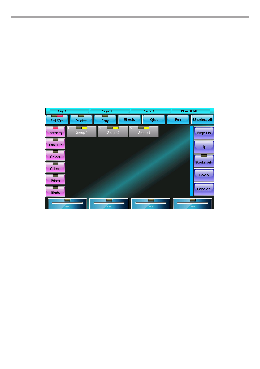
1.2 GROUP DISPLAY
The groups window is identical, in both form and features, to the xtures window, except for the fact that
the selection is made for groups; by pressing a group button, all the xtures therein can be alternately
selected and de-selected.
The organization of the xtures into groups is particularly useful when a show includes many xtures
and these are often managed together in recurring groups.
As for the xtures, each group button has two leds: the rst informs us on the status of the channels
(when switched o, all parameters of all the group xtures are Empty; when red, all parameters of all the
group xtures are controlled by the editor; for all other cases, the LED is orange).
The context-specic menu is identical to the context-specic menu of the xtures window, with the
exception of the Select Range button which does not appear here.
PULSE MX
Group display editor mode Fig.15
Create/edit a group
To create a new group you must select the xtures that will be part of the group, press the Group button
on the Store Menu (recall by pressing the Store key), and then type the name of the new group to be
created using the virtual keyboard.
IMPORTANT: If a group already exists with the same name, the old group is overwritten.
To edit a group you proceed as just described, paying attention when inserting the name of the group
you want to edit
1.3 PALETTES DISPLAY
Palettes are predened memories which speed up programming; each xture usually already has some
predened palettes in the fdf le, but the user can create new personalised ones. The preparation of
pan-tilt palettes is very useful in that, once preparation of the palettes is complete, the pointing of the
xtures is done simply by selecting the xtures concerned and then clicking on the palette of the desired
location.
IMPORTANT: When programming the cues with the palette, make sure the reference to the palette is saved
rather than the values contained in it; in this way, when you edit a palette, the changes made will be reected
on all its cues. This photo is particularly useful to make positioning amendments on previously programmed
shows.
The palettes are organised in the 6 parameter families: Intensity, Pan/Tilt, Colors, Gobos, Prism and Blade
Page 23
PULSE MX
which can be selected by pressing the corresponding button.
The palette window displays all available palettes for the set of xtures selected in the current family; if
no xture is selected, then all the palettes in the current family’s show will be displayed.
The palette window shows a context-specic menu which button is practically identical to the contextspecic menu of the xtures window, however the Select Range does not appear.
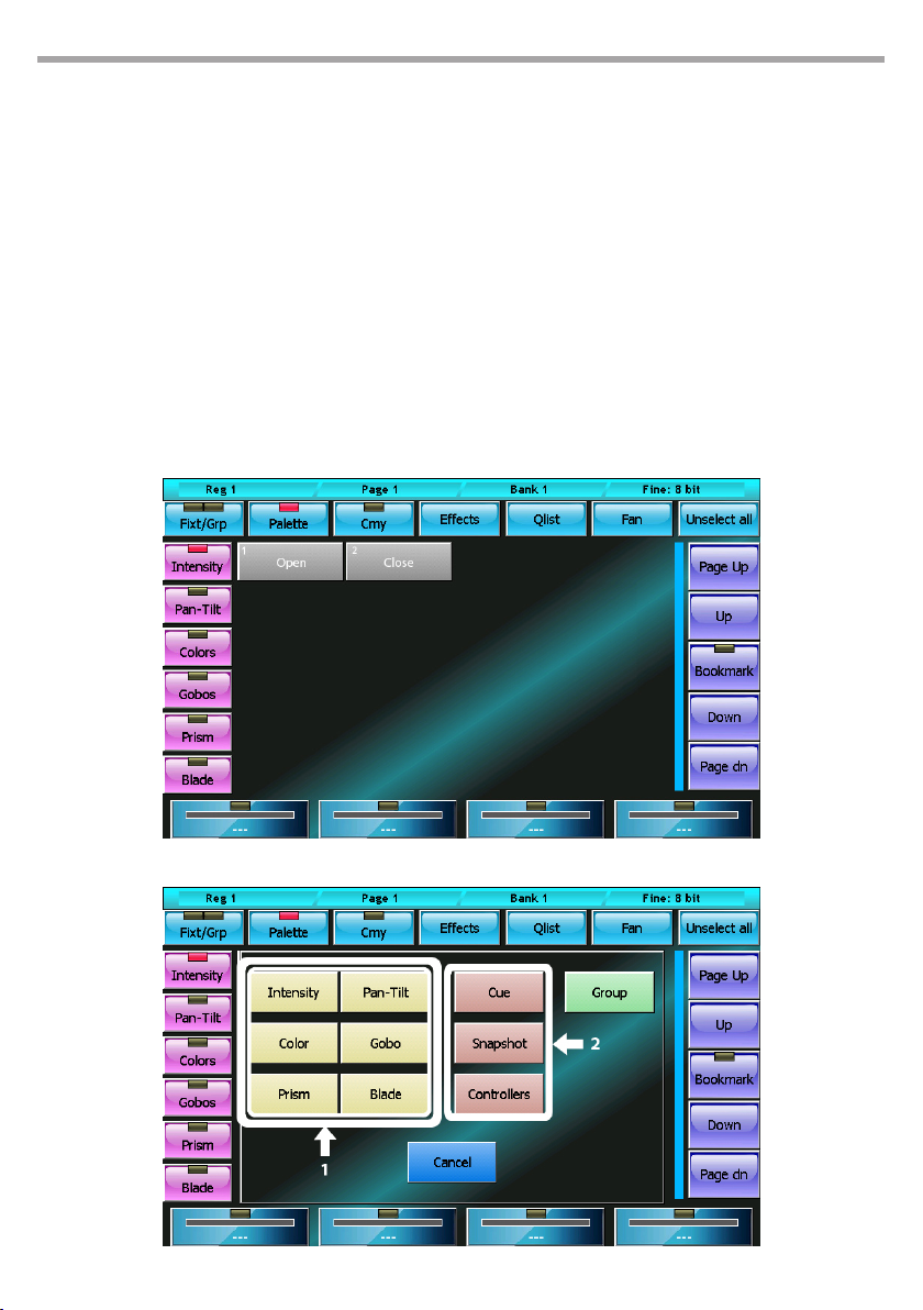
CREATING A NEW PALETTE
After having set the parameters of the xtures to the desired value, you can save their status in a new
palette by recalling the Store menu which is done by clicking the Store key; select the type of palette
you wish to save (buttons 1) and then insert the name of the new palette you wish to create by using
the virtual keyboard.
IMPORTANT: when creating a new palette, only the parameters which belong to the same type of the created
palette are saved.
23
Palette display editor mode
Store menu
Fig.16
Fig.17
Page 24
24
Editing an existing palette
To edit an existing palette, do as follows:
• Select the palette by pressing the corresponding button,
• Press the Load key (the Load key loads the last palette used into the editor)
• by using the features of the editor, carry out the necessary changes
• nally, press the Update key, which will substitute the old palette with the new values.
IMPORTANT: if you edit a palette, all the cues which referred to this palette will consequently be modied.
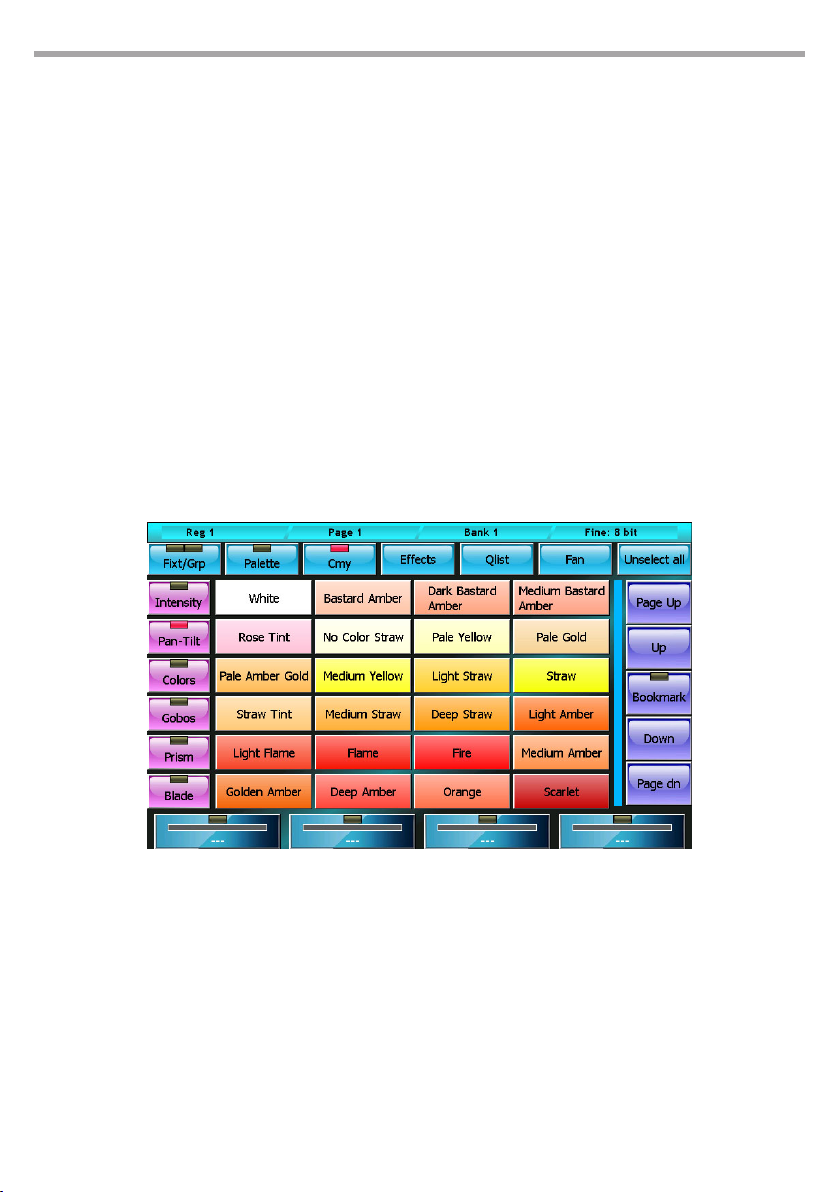
1.4 PREDEFINED PALETTES
The console has four sets of predened palettes (Chris, Gam, Lee and Rosco) with RGB and CMY color
mixing system.
The window of the predened palettes (to display, press the CMY button) displays the palettes of the
current set which can be set in the General Options menu located in the Setup Menu.
The predened palettes can be identical to the user palette, but these cannot be edited.
In this display mode, the wheels and the Intensity, Pan-Tilt, Colors, Gobos, Prism and Blade buttons
maintain the same features as in the xtures display mode.
PULSE MX
Editor: Rosco Palette display Fig.18
1.5 CONTEXT-SPECIFIC MENU
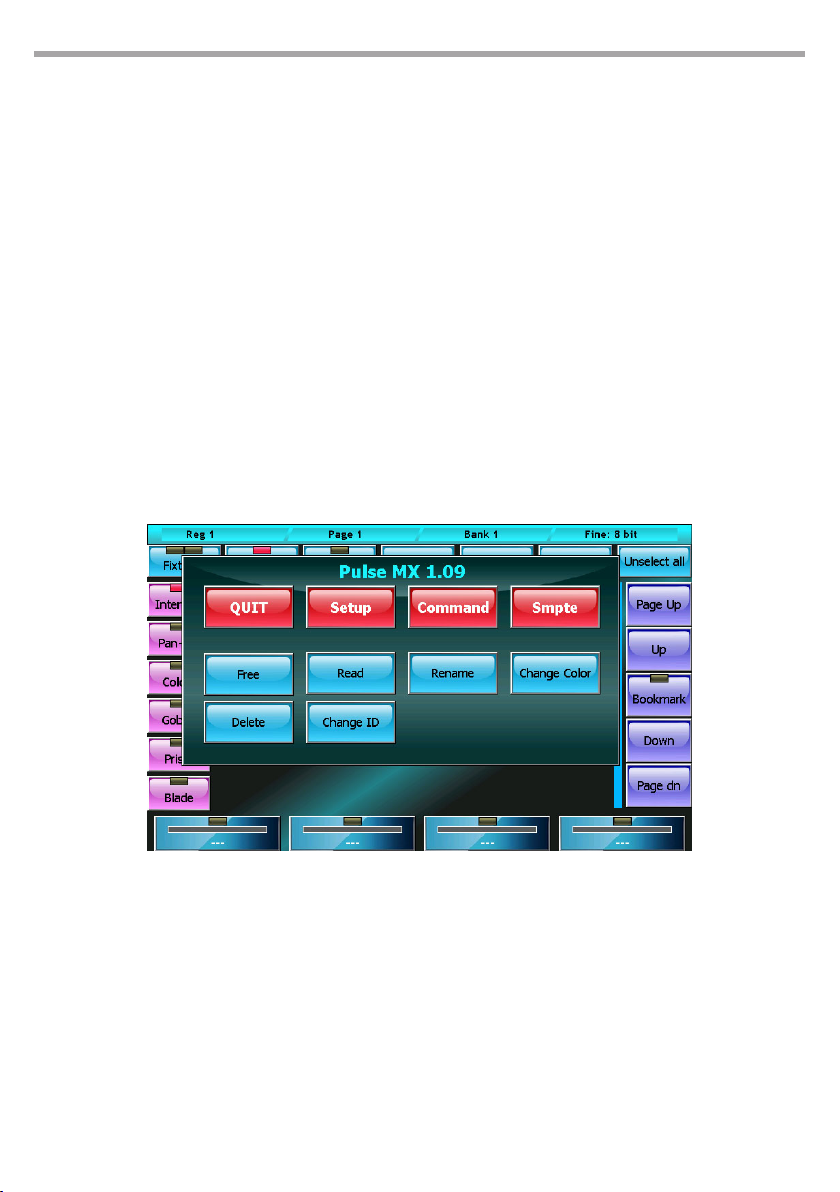
The context-specic menu of the editor has the following buttons:
Free
Sets all the parameters of the selected xtures to “Empty”
Read
Copies all the current available output values into all the parameters of the selected xtures This command ensures that all parameters of the selected xtures are set to a not Empty value and therefore
saving a cue stores the complete status of the xtures (and not just the directly assigned parameters)
Page 25
PULSE MX
IMPORTANT The Read command reads the status of the DMX and therefore loses the information of any
paletted values or eects. In this case, the instant value of the parameter is considered.
Rename
Opens the virtual keyboard to edit the name of the selected xture
Change color
Opens the color picker window to select a new color to apply to the buttons of the selected xtures.
Change Id
opens the virtual number keyboard to edit the IDs of the selected xtures. The xtures ID determines
the order in which the xtures are displayed in the editor; the IDs can be whole numbers or numbers
with two decimals.
If two or more xtures are selected, they will be assigned progressive IDs.
Select Range
The xtures can be selected directly from the ID as well as by pressing the corresponding buttons.
By pressing the ID button, a virtual number keyboard appears: insert the maximum and minimum ID
values corresponding to the xtures to be selected, separating them with a dot, and conrm.
25
Context-specic menu Fig.19
Page 26
26
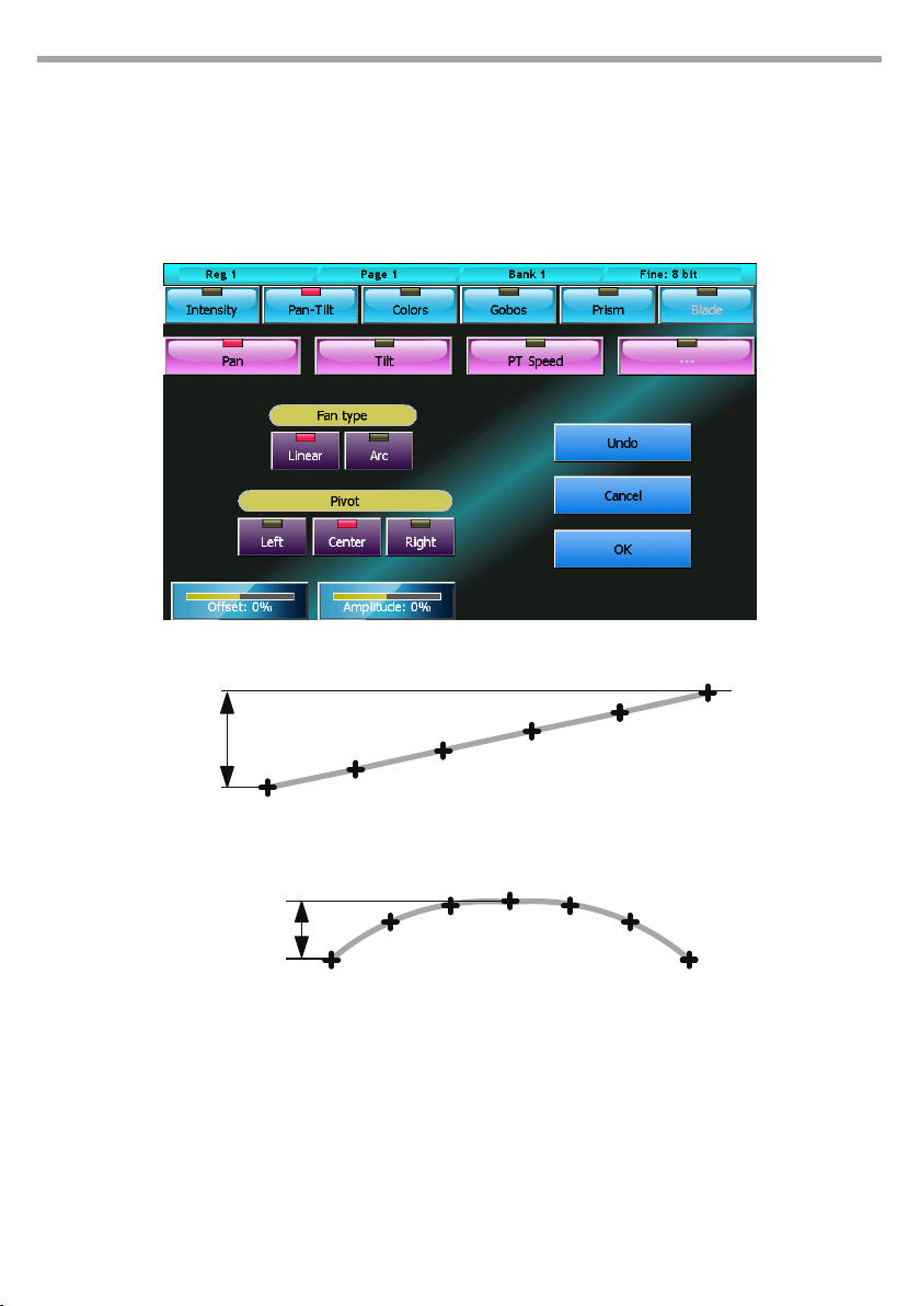
1.6 FAN
The fan feature assigns a sequence of values to the same attribute of the selected xtures. The sequence
of values can follow the trend of a ramp or of a semicircle.
Once having selected all the xtures involved in the editor, press the Fan button and the corresponding
window will appear.
PULSE MX
Fan window
Fig.20
Amplitude
Linear Fan
Amplitude
Arc Fan
Example of a Linear to Arc Fan
The two series of buttons at the top allow you to select the parameter you wish to edit; in the illustrated
case, we are working on the pan. The distribution of the values assigned is inuenced by 4 factors:
Fan-type buttons
• Linear: selects a linear distribution of the values (that is to say that the values assigned to the
xtures will be equally spaced)
• Arc: assigns values according to an arc path
Fig.21
Page 27
PULSE MX
27
Pivot buttons
Enables to select the pivot element of the group, that is to say the element which remains xed in
position and around which the others move. It is possible to select the rst xture (left), the last
xture (right) or the central xture (Center); if the number of xtures is even, the xed value will be
the intermediate value between the two central xtures.
Offset wheel
Moves all values in parallel in the same direction, increasing or reducing them in equal measure.
Amplitude wheel
Increases or decreases the amplitude of distribution; negative values are also acceptable.
1.7 EFFECTS
An eect is the predened trend of a value which is repeated in cycle in time and which can be applied
to any parameter of one or more xtures; speed and amplitude can be edited by the operator.
A typical eect is the Circle which, when applied to the pan and tilt of the xture, force them to follow
circular trajectories on the stage. Dierent xtures can share the same eect in order to move in a
coordinated fashion.
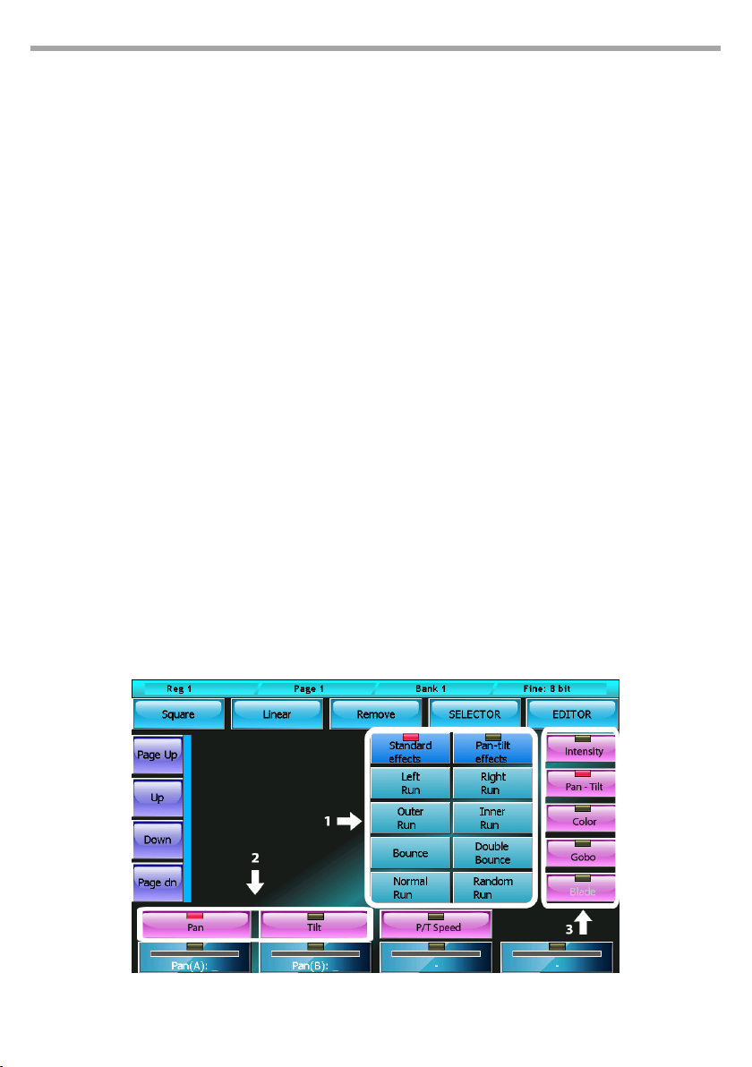
To apply an eect to an attribute of the previously selected xtures, do as follows:
• select the attribute interested by the eect by choosing its family; to do so, press one of the buttons
on the right and then press one of the attribute buttons placed horizontally on the wheels
• select the minimum and maximum values of the wave-form by clicking on the palette buttons or
operating on the rst two wheels
• with the linear and square buttons, it is possible to select the wave-form (respectively sinusoid and
square wave)
• The third wheel (Period) enables to vary the speed of the eect.
When two or more xtures are involved, it is possible to obtain “Mexican wave” type eects by operating
on the fourth wheel (Spread) and on the phase eect selection buttons
Movement eects generator for pan and tilt
1)1. Selection phase 2)2. Parameter selection 3)3. Family attribute selection
Fig.22
Page 28
28
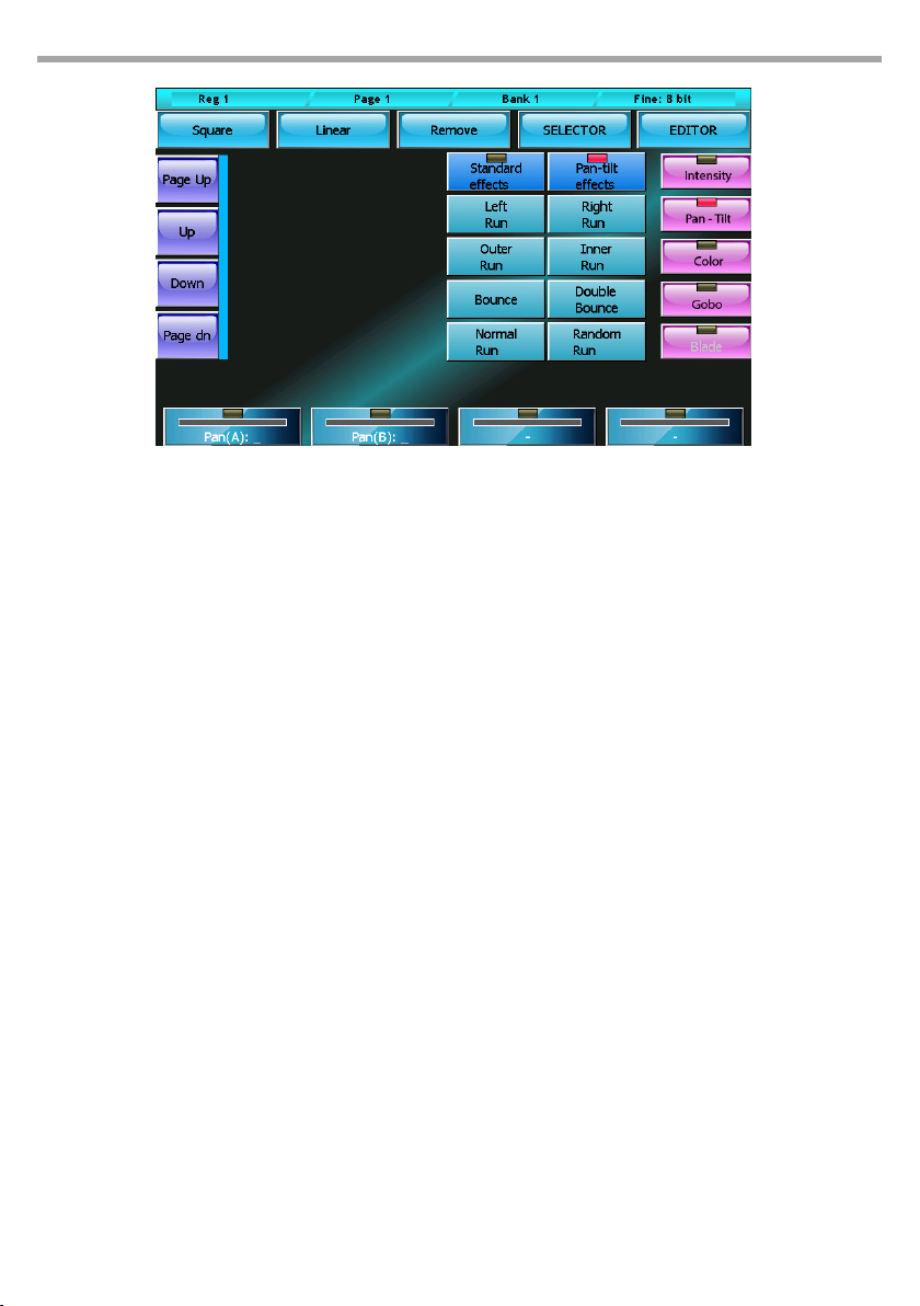
Eects window Fig.23
In the case of movement eects applied to the pan and tilt of the xtures, the situation is slightly dierent
as the movement is dened by the central or base point (which is set by pressing the palette buttons or
operating on the rst wheel) and the amplitude (set by using the second wheel). In the case of the Circle
eect, the pan e tilt share the same amplitude value, while the two values are independent from one
another in all other cases. The two Left/Right and Sync/No Sync buttons at the top are used to generate
chasing eects in case two or more xtures are used.
PULSE MX
The Remove button removes the applied eect.
The Selector button recalls the selector window.
EDITING AN EFFECT
To edit an eect which had previously been saved in a cue: load the cue into the editor, select the xtures
involved and nally open the window of the eects generator to edit. If the show contains many xtures
and if one cue contains more groups of xtures with dierent eects, selecting the xtures may be a
dicult task. In this case, the Selector window helps analyse the content of the cue and recreates the
groups of xtures which have the same eect. To open, simply press the Selector button when you are
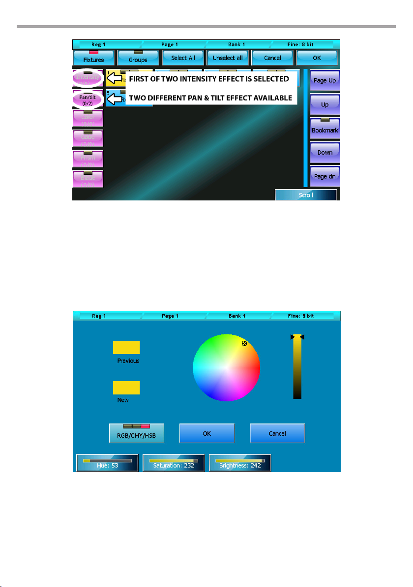
in the eects generator window. The column button on the left highlights how many groups of xtures
contain eect for each family of attributes. (for example, in the picture there is a cue which contains 4
groups of xtures having as many eects: two Intensity eects and two Pan/Tilt eects).
Press the buttons on the left to scroll (and select) in sequence the groups of xtures having the same
eect.
Once having identied the group which contains the eect to be edited, press OK to go back to the
eects generator window and edit.
Page 29
PULSE MX
Selector window Fig.24
1.8 COLOR PICKER
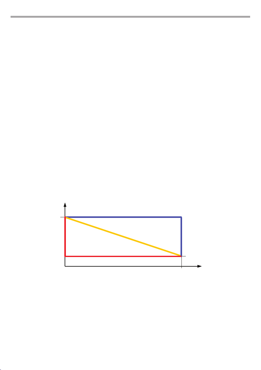
The color picker window is used to change the color of the buttons relating to dierent types of objects
(Fixtures, palettes, cues...)
Colors can be selected directly from the bitmap (1) or using the rst three wheels; the RGB/CMY/HSB
button selects the input mode scrolling through the three available colors (Red/Green/Blue, Cyan/
Magenta/Yellow and Hue/Saturation/Brightness).
29
Color picker Fig.25
Page 30

30
PULSE MX
- 2 - PLAYBACK
Playback is the moment when the programming activity of the show is nalised or the execution phase
of the show.
The console provides the operator with up to 48 qlists at the same time (24 if the expansions are not
connected) and up to a maximum of 12 manual cues (according to how the controllers have been congured)
The result of the elaboration of the parameters is dened by the active cues and the controllers (controllers here are to be intended as those which have been congured in manual cue). The parameters which
aren’t involved by the active cues and the manual cues are set in Standby mode; if the Standby mode is
not dened, then the output remains stable on the last value set by a cue or a manual cue.
IMPORTANT: the editor and Hilite key always have priority on playbacks and controllers, therefore, with the
exception of specic cases, the transmission of a show occurs after having set the editor to zero (double click
on the Clear key).
2.1 CUE INPUT
When two or more cue lists compete for a channel, the following criteria is applied (depending on the
Playback mode option setting in the General Options window):
• HTP channel: the cue which has received the most recent trigger gains control of the channel, regardless of the Playback mode settings
• HTP channel and Playback mode=LTP the criteria of the previous point is applied
• HTP channel and Playback mode=HTP is considered the highest value of all the cues contending the
channel
For each channel, the console stores the organised list of cues which in time have passed the control of
the channel to one another, so that if the last cue were to be disabled, the control of the channel would
be given back to the previous cue and so on until the rst cue.
If no cue controls the channel, the channel is put in standby mode (if the stand by value has been dened), otherwise it is left as it is; the dimmers are usually set to zero while the remaining channels remain
unaltered.
Activating a cue
To activate a cue, just press the corresponding playback key. Following this operation, other cues
may activate in sequence, depending on how the cue list is congured (see Chap.3 Cue-list, paragraph Qlist Mode).
The master playback is internally set at 100% with the exception of playbacks which have controllers
congured as playback masters, in which case the slider becomes the master playback.
A cue can also be activated through the cue-list window in Live mode (see Chap.3 Cue-list, paragraph Live Mode).
IMPORTANT: the default conguration of the controller is Playback master which means that playbacks 1
to 12 have both an intensity slider and a ash key, while playbacks from 13 to 24 only have a trigger key.
Switching off a playback
To ‘turn o’ a playback, press the Release key and the playback key or alternatively press in quick succession the Release key and playback key (before the LED of the Release key switches o).
Change page
When changing page, all playbacks are assigned a cue list in the new page, with the exception of
playbacks which aren’t switched o; active playbacks continue to control the cue list until they are
disabled. Only after the playbacks are disabled, they will be assigned a new cue list.
Page 31
PULSE MX
31
2.2 CONTROLLER INPUT
After having calculated the input of the active cues of the playbacks, the console determines the input
of the controllers: in Manual cue mode, the controller slider controls the cross-fade between the manual
cue and the cue playback processing result; in practice, when the slider is at zero, the controller cannot
give any input; if the slider is at 100%, the playback cues are ignored and the controller cue takes priority;
in intermediate cases, to determine the nal value, the following criteria, which also depends on how the
manual cue was saved, is applied.
• All channel fade: the nal value is the linear combination between the value of the controller and the
result of the processing of the cues: the closer the slider is to 100%, the greater the inuence is of the
controller and the lower the Cue input and vice versa (linear path).
• Snap Start: channels which have path = Linear follow the All channel fade criteria, while to channels
with path = Snap_start or Snap_end the following criteria is applied: if the slider is 0, the value of the
playback cues appears (the controller gives no input); if the slider is above 0, the controller value
appears.
• Snap End: the channels which have path = Linear follow the All channel fade criteria, while the channels with path = Snap_start or Snap_end the following criteria is applied: If the slider is lower than
100%, the value of the playback cues appears (the controller gives no input); if the slider is equal to
100%, the value of the controller appears.
A direct consequence of this algorithm is that if the manual cue contains a zero, then by raising the controller slider to 100%, the value of the channel is taken to zero. The elaboration of the controllers is done
according to the chronoplaybackical order of their activation, therefore if one same channel is involved
in two manual cues, an intermediate result is calculated rst, by applying the calculation criteria while
considering the “oldest” controller, and then the intermediate result is elaborated again using the most
recent controller.
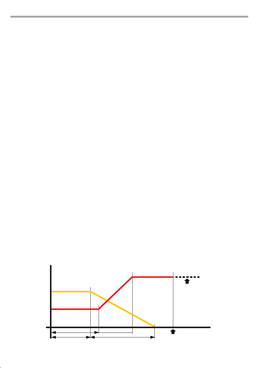
Resultant Value
Cue Value
0%
The drawing above is the graphical representation
of 3 algorithms
Snap end path
Linear path
Snap start path
100%
Fig.26
Manual cue
Value
Slider position
Activating a manual cue
To activate a controller, just move the slider away from zero; if the slider of a controller is place on
a value other than zero, rst take the slider to zero. In any case, pressing the ash key activates the
controller which returns to its previous status when the key is released.
Switching off a controller
A controller can be disabled by setting its slider at zero. It is automatically disabled if other controllers or the editor take away channel control. To reactivate the controller, set the slider at zero and
then raise it to the desired value.
Page 32

32
Change Bank
When changing bank, all controllers congured in manual cue mode One for each bank, will control
the manual cue it has been assigned in the new bank. If a manual cue is active, it will stay active and
continue to give its contribution even by changing bank.
It is important to note that in such a situation, there is no control on the console capable of controlling the above-mentioned manual (except Release All); to regain control, it is necessary to change
the bank once again and return to the previous bank and then move the controller slider until crossing the original value of the manual cue.
A controller congured in Manual cue, Fixed mode is not inuenced by the bank change and keeps
controlling the same manual cue.
2.3 GRAND MASTER AND GROUP MASTERS
You can intervene in real time on the result of the cue and manual cue elaboration using the Grand Master (and DBO key) and group masters.
The Grand Master only inuences the HTP channels (typically the xtures dimmer) proportionally reducing their value.
The controllers can be congured as group masters (see Controllers paragraph); in this case, we could
have up to 12 intensity masters corresponding to as many groups..
A group master, just like a Grand Master, proportionally reduces all HTP channels of the xtures belonging to the group itself.
IMPORTANT: if a xture belongs to more groups, the lowest master is considered.
PULSE MX
Page 33
PULSE MX
33
- 3 - CUE LIST
A cue list (or qlist) is an organised group of cues. Each cue contains information on the status of one or
more parameters belonging to one or more xtures and the information relating to its trend in time.
Each cue list can be congured according to four dierent modes: Qlist, Chase, Sequence or Live. Depending on the mode, the way in which the cues are triggered and the calculation of their timing changes.
3.1 QLIST MODE
The evolution of a cue in time is determined by the trigger and evolves according to the times inserted.
Delay, Fade-in, Wait e Fade-out. Cues are triggered either by pressing the playback key which controls it
or due to a predened event on one of the input ports.
• Delay: time between the trigger and actual activation of the cue
• Fade-in: fade in time of the cue
• Wait: time between the trigger and fade out
• Fade-out: fade out time
IMPORTANT: Delay+Fade-in and Wait+Faid+out times dene two time lines and are not in sequence
Time evolution of a cue which has received a trigger:
• At the Delay stage, the LTP e HTP attributes set at values other than zero, start to move towards the
nal value will reach it in a time equal to the Fade-in.
• At the Wait stage, the LTP e HTP set at zero or Empty start to move towards zero and will reach it in a
time equal to the Fade-out.
• At the Delay+Fade-in stage, the entrance stage of the cue is completed (all LTP and HTP attributes
with values other than zero and not Empty will have reached the nal value)
• At the Wait+Fade-out stage, all the HTP attributes with values other than zero and not Empty will
have completed the fade-out and will be at zero value.
• Once the fade-in is completed, if the Link next cue button is active, the next cue will automatically
receive a trigger; otherwise, all outputs remain the same until the following trigger arrives.
Wait and Fade-out times are optional; if not inserted, they are considered to be equal to Delay and Fadeout times.
HPT fade out
LPT & HTP fade in
Delay
Wait
Fade-in and Fade-out trend in time Fig.27
Fade in
Fade out
Next trigger
Value
controlled by
next cue
time
Page 34
34
PULSE MX
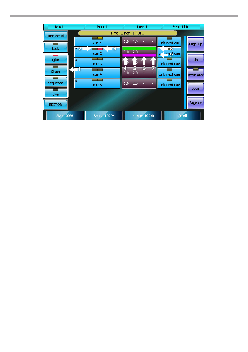
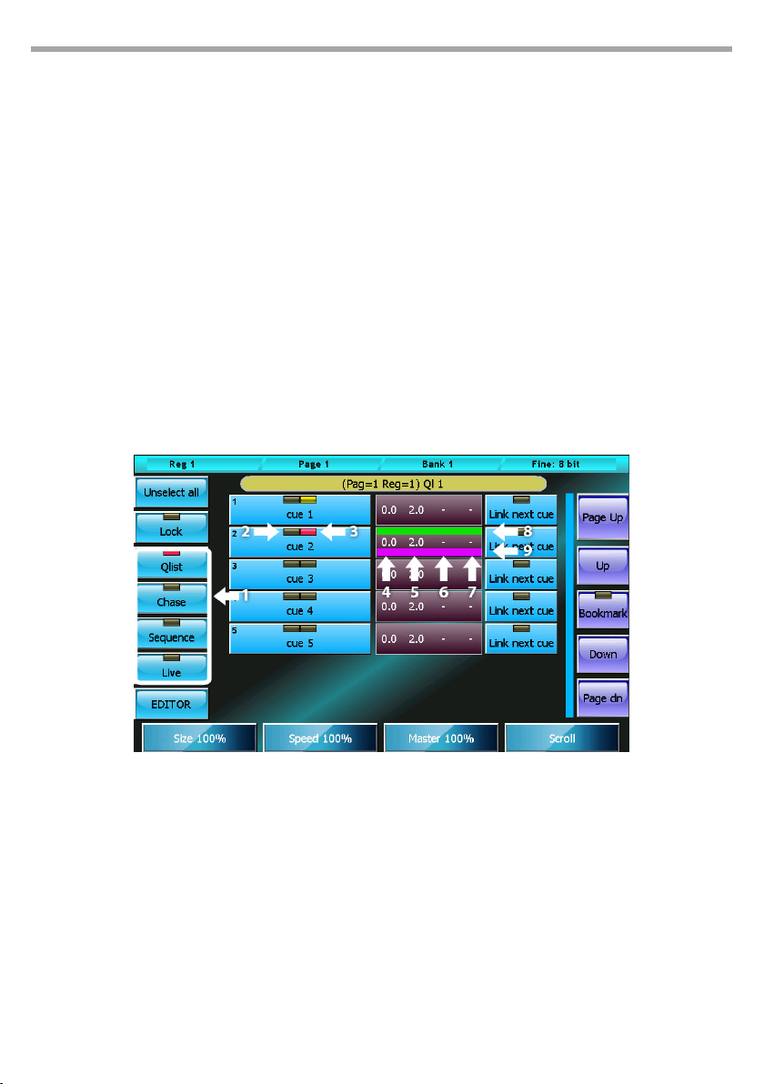
Cue list in Qlist mode
Fig.28
1. Cue list mode selection buttons
2. Cue selection leds: red=selected, o=not
selected
3. Execution led: o, cue not in execution, yellow=
cue execution completed, red= in execution
4. Delay time in seconds
5. Fade-in time in seconds
6. Wait time in seconds, '-' means value not inserted
7. Fade-out time in seconds, '-' means value not
inserted
8. Delay+Fade in timeline bar
9. Wait+Fade-out timeline bar
Buttons:
• Unselect all: Deselects all cues
• Lock: when activated to edit the current qlist, a clear command is needed; this can be done via the
Select button, otherwise simply trigger a qlist to make the cue list current.
• Qlist, Chase, Sequence, Live: cue list mode selection buttons
• EDITOR: recalls the editor window.
• Link Next cue: if activated, upon completion of the Fade-in, it sends an automatic trigger to the
following cue
Wheels:
When one or more cues are selected, the wheels allow you to respectively set Delay, Fade-in, Wait
e Fade-out times; if there are no cues selected, the wheels respectively become Master Size, Master
Speed, Master Intensity and Scroll wheel.
IMPORTANT: during playback, it could be useful to use the wheels to regulate in real time the amplitude
(Master Size) and the speed (master Speed) of the eects of the cue or the intensity of the dimmer (Master
Intensity). These three values are not saved on the disk and every time the cue list is activated they return
to their default values.
Page 35
PULSE MX
3.2 CHASE MODE
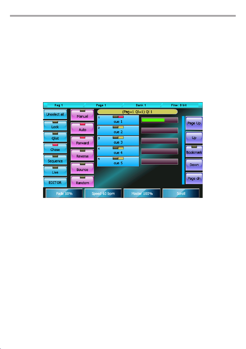
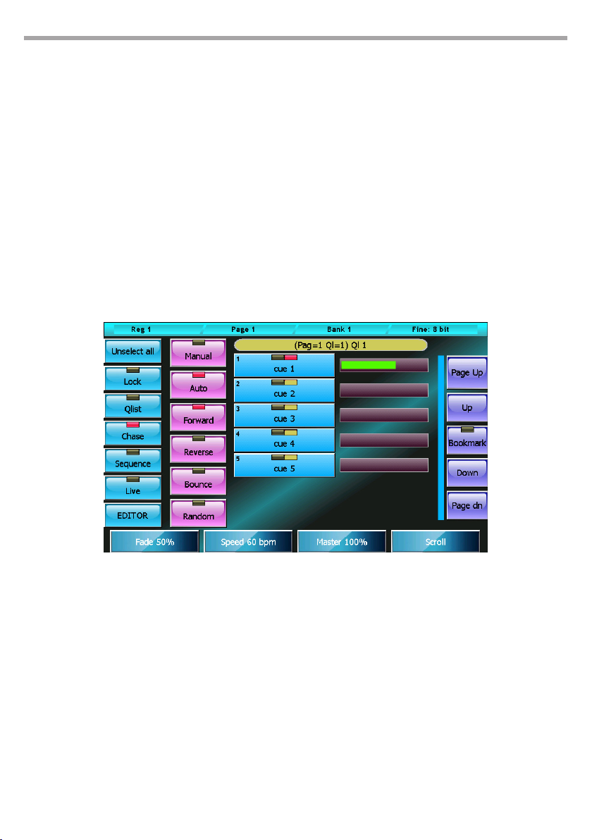
In a cue list congured in Chase mode, all cues are assigned a common timing, and timings at single cue
level are disregarded. If the Auto mode is active, upon every Fade-in completion, a trigger is automatically sent to the following cue; on the other hand in Manual mode, to activate the following cue a clear
trigger is necessary. One of four options can be selected for the execution order of the cues:
• Forward: the cues are executed in the natural order, that is to say from the rst to the last and then
starting again from the rst
• Reverse: the cues are executed in a reversed order
• Bounce: the cues are executed from the rst to the last and then backwards from the last to the rst
and so on
• Random: the cues are executed in a random order.
35
Cue list in chase mode Fig.29
Bottons:
• Unselect all: Deselects all Qlists
• Lock: when activated to edit the current qlist, a clear command is needed; this can be given via
the Select button, otherwise simply trigger a qlist to make the cue list current.
• Qlist, Chase, Sequence, Live: cue list mode selection buttons
• EDITOR: recalls the editor window.
• Manual: each cue must be activated by a manual trigger
• Auto: the cues are automatically activated in sequence
• Forward, Reverse, Bounce e Random: cue activation order selection buttons
Wheels:
The rst three wheels are used to set the timings which refer to all cues, while the fourth wheel controls the window scrolling. The common values which can be set with the wheels are:
• Fade: percentage of cue time dedicated to Fade-in
• Speed: speed of the cue expressed in beats per minute; the cue time in seconds is calculated as
60/Speed.
• Master: master of intensity
If for example we had set Fade=40% and Speed=15 bpm in Auto mode, we would have a total cue
time of 60/15=4 seconds with a Fade-in of 4*40/100= 1.6 seconds; therefore, the cues would take
1.6 seconds to perform the fade-in and would be activated every 4 seconds. In any case, in Manual
Page 36
36
mode we would have a Fade-in time of 1.6 seconds, but activation of the cues would remain under
the control of the operator.
IMPORTANT: during playback, it could be useful to use the wheels to regulate in the real time the amplitude
(Master Size) and speed (master Speed) of the cues or the intensity of the dimmer (Master Intensity). These
three values are not saved on the disk and every time the cue list is activated they return to their default values.
3.3 SEQUENCE MODE
In Sequence mode, the cues are automatically activated upon fade-in completion of the previous cue;
the order of activation is the natural one, that is to say from the rst cue to the last and then starting
again from the rst.
IMPORTANT: when the rst cue of the sequence is activated for the rst time, the Delay time is disregarded,
that is to say that when a trigger is sent to a sequence, this is done disregarding the Delay of the rst cue,
which will be considered normally in the following automatic activations.
Wait and Fade-out times cannot be inserted in this mode and are considered identical to the Delay and
Fade-in times
PULSE MX
Cue list in sequence mode
1. Cue list mode selection buttons
2. Cue selection leds: red=selected, o=not
selected
3. Execution led: o, cue not in execution, yellow=
cue execution completed, red= in execution
4. Delay time in seconds
5. Fade-in time in seconds
6. Delay+Fade in timeline bar
Buttons:
• Unselect all: Deselects all Qlists
• Lock: when activated to edit the current qlist, a clear command is needed; this can be given via
the Select button, otherwise simply trigger a qlist to make the cue list current.
Fig.30
Page 37
PULSE MX
• Qlist, Chase, Sequence, Live: cue list mode selection buttons
• EDITOR: recalls the editor window.
• Link Next cue: button disabled in this mode
Wheels:
The wheels are used in two separate ways: if one or more cues operating on the wheels are selected,
the Delay e Fade-in times are set; otherwise, the wheels allows you to set the Master Size, Master
Speed, Master Intensity. The fourth wheel is always used for window scroll.
IMPORTANT: during playback, it could be useful to use the wheels to regulate in real time the amplitude
(Master Size) and the speed (master Speed) of the eects of the cue or the intensity of the dimmer (Master
Intensity). These three values are not saved on the disk and every time the cue list is activated they return
to their default values.
3.4 LIVE MODE
A cue list in Live mode allows you to activate single cues directly from the touchscreen: by pressing a button of the window, a trigger is sent to the corresponding cue which becomes active and is transmitted.
In this way, the cues of the cue list can be activated in any given order depending on your requirements
at any given time.
The timings of the cues are the ones inserted in Qlist mode; this window, due to space and opportunity,
does not allow to insert times; therefore this activity is to be performed with the cue list in Qlist mode.
Once the timings have been inserted, the Live mode can be set; of course, it is possible to return to the
Qlist mode at any point to make amendments to the times and then return to the Live mode.
37
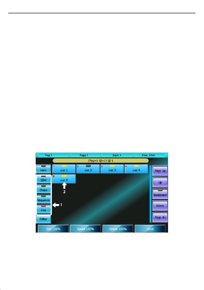
Cue list in Live mode
1. Cue list mode selection buttons
2. Cue status led: red=last triggered cue,
yellow=previously triggered cue
Fig.31
Page 38
38
Buttons:
• Lock: when activated to edit the current qlist, a clear command is needed; this can be given via
the Select button, otherwise simply trigger a qlist to make the cue list current.
• Qlist, Chase, Sequence, Live: cue list mode selection buttons
• EDITOR: recalls the editor window
IMPORTANT: in this mode, the Lock button is particularly important as it ensures control of the cue list is
not lost when other playbacks are activated.
The Live window is to be considered as an extension of the physical commands of the corresponding
playback; when changing page, the Live window will show the cue list corresponding to the new page
regardless of the Lock button status.
Only if the cue list is active will the window continue to show the same cue list, until this cue list is released.
3.5 CONTEXT-SPECIFIC MENU
The four cue list modes share the same context-specic menu:
PULSE MX
Cue list context-specic menu Fig.32
Buttons:
• Rename Qlist: activates the digital keyboard in order to assign an new name to the cue list.
• Copy Qlist: duplicates the current cue list and assigns it to a new playback: when open, the virtual
numeric keyboard digits the number of the page and of the destination playback separated by
a dot.
• Delete Qlist: deletes the current cue list and all the cues contained in it.
• Rename Cue: opens the virtual number keyboard to edit the name of the selected cue.
• Copy Cue: duplicates and adds the selected cues to the end of the Qlist
• Delete Cue: permanently deleted all selected cues after conrmation
• Move Cue: opens the virtual number keyboard to assign a new ID to the selected cue; IDs can be
whole numbers or numbers with two decimals.
• Change color: opens the color picker to change the color of the buttons of the selected cues.
Page 39
PULSE MX
39
- 4 - CONTROLLER
The controllers can be congured in three dierent ways using the Controller Conguration feature, accessible from the Setup menu:
• Playback master (default conguration)
• Group master
• Manual cue
The conguration of each controller is completely independent; therefore, it is possible to obtain any
combination of modes.
4.1 CONTROLLER CONFIGURATION
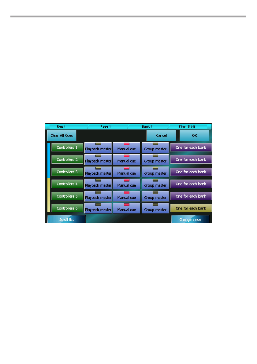
Press the Controller conguration button from the Setup Menu to access the window.
Controller conguration window Fig.33
Buttons:
• OK: saves the changes and returns to the Setup menu
• Cancel: returns to the Setup menu without saving any changes
• Clear all cues: deletes, after conrmation, all controller cues of all banks.
Playback master mode:
In this mode (playback master), the slider and the controller key become master and ash of the
corresponding playback (i.e. controller 1 becomes master and ash of playback 1, controller 2 of
playback 2 and so on until controller 12; playbacks 13 to 24 cannot have a master)
Group master mode:
In Group master mode (group master), the slider becomes the master of intensity of all xtures belonging to the group allocated to the controller.
IMPORTANT: If a xture belongs to two or more distinct groups that are assigned to as many controllers,
the xture will be lowered according to the lowest value of the sliders.
Page 40
40
Manual cue mode:
In this mode, it is possible to associate a single cue to the controller (Fixed mode) or up to 24 dierent
cues organized in as many banks (mode One for each bank).
In Manual cue mode the slider controls the cross-fade between the controller’s cue and the playback
processing result; in practice, when the slider is at zero, the controller cannot give any input; if the
slider is at 100%, the controller’s cue is transmitted; in intermediate cases, the actual contribution of
the controller depends on how the controller cue has been saved:
• All channel fade: the nal value is the linear combination between the value of the controller and
the result of the processing of the cues: the closer the slider is to 100%, the greater the inuence
is of the controller and the lower the cue input and vice versa (linear path).
• Snap Start: channels which have path = Linear follow the All channel fade criteria, while to channels with path = Snap_start or Snap_end the following criteria is applied: if the slider is 0, the
value of the playback cues appears (the controller gives no input); if the slider is above 0, the
controller value appears.
• Snap End: the channels which have path = Linear follow the All channel fade criteria, while the
channels with path = Snap_start or Snap_end the following criteria is applied: If the slider is lower
than 100%, the value of the playback cues appears (the controller gives no input); if the slider is
equal to 100%, the value of the controller appears.
Saving a manual cue:
To save a cue in a controller, press Store + the ash of the controller (press and hold the Store key
while pressing the ash key on the controller).
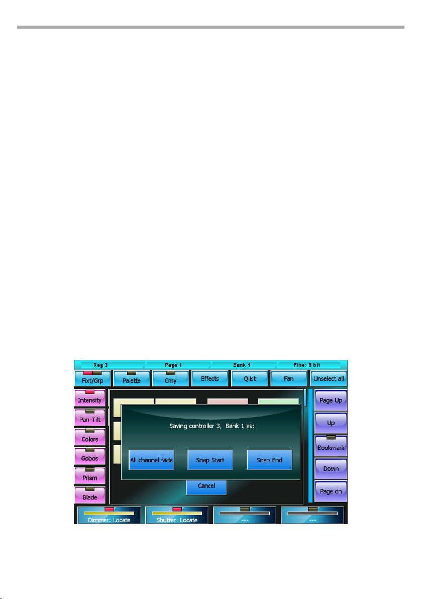
Cues can be saved in 3 dierent ways: All channel fade, Snap Start, or Snap end.
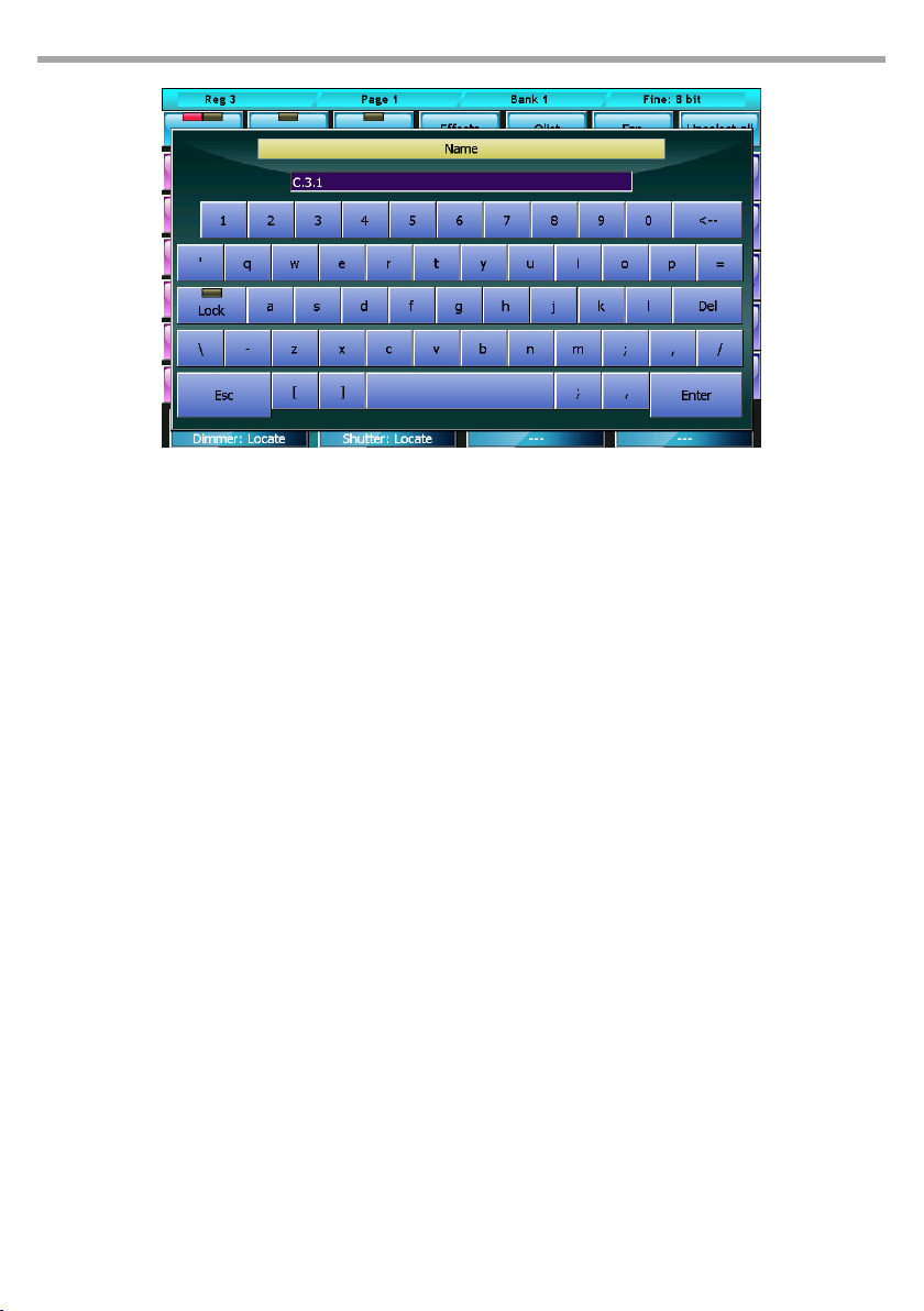
When you save, the console allows you to assign a reminder tag to the controller; although you can
enter up to 30 characters, due to space constraints, only the rst 10 appear on the alphanumeric
console display on the controller.
PULSE MX
IMPORTANT: The manual cue does not support eects; potential eects in the editor will not be saved.
Save controller: select mode Fig.34
Page 41
PULSE MX
Save controller: insert tag Fig.35
Editing a manual cue:
to load it in the editor, press the key Load + the ash of the controller (Press and hold the Load key
while pressing the ash key of the controller). Once you have completed your changes, simply press
the Update key to Update the values of the manual cue.
Changing the current Bank
To move to the next bank, press the Bank key twice in quick succession. To switch to a random bank,
press the Bank key in quick succession and the playback key of the desired new Bank (or press bank
key + playback key). The status bar of the console will reect the change.
The bank change inuences only the number One controllers of each bank (the Fixed controllers
always control the same cue, regardless of the current bank).
When you change a bank, you can no longer intervene on the active manual cues of the previous
bank, as the sliders and the controller keys control the cues of the new bank. Activation of new cues
happens when the slider passes through 0.
To regain control of the cues which are active in a bank other than the current one, you must activate
the bank in question crossing the old controller value with the slider.
41
Page 42
42
PULSE MX
- 5 - SETUP
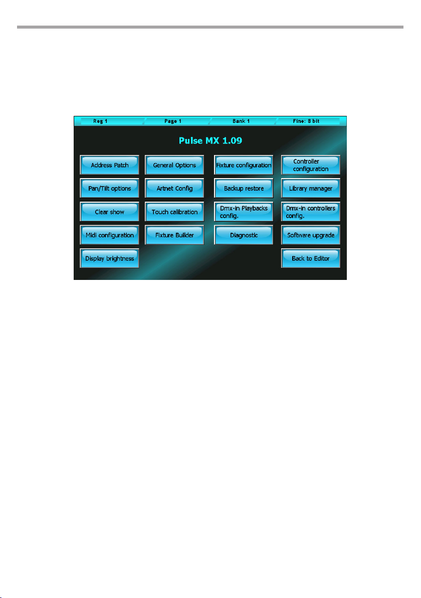
Setup and utility functions can be accessed from the console Setup menu. To access the Setup menu,
press the Setup button which always appears in the context specic menu. A brief overview of the single
functions is given below:
Setup menu Fig.36
Address patch:
Allows access to the patch window which enables to add or take out xtures from the conguration
of the show and set their DMX addresses.
General options:
Allows to set up general options which modify some specic behaviour of the console.
Fixture configuration:
Allows to edit the conguration of xtures used in the current show. All changes applied through this
function only aect the current show, leaving the xture library unchanged.
Controller configurations:
Conguration and personalisation of all Controllers.
Pan/Tilt options:
Allows to invert and swap the Pan and Tilt function of the show’s xtures.
Artnet configuration:
Conguration of Ethernet port and Artnet connector.
Backup restore:
For managing and restoring saved show les (both from internal memory and USB drive)
Library manager:
Manages the xture library. Allows to import and/or export single les or folders from the internal
Page 43

PULSE MX
memory to a USB drive and vice versa.
Clear show:
Completely erases all show data including cue lists and patch data, and restores default conguration Fixture libraries and all backup les stored in the internal memory are not erased.
Touch calibrations:
Touchscreen calibration. In general, the console is delivered with a properly calibrated touchscreen,
but it can be newly calibrated whenever needed. To calibrate the screen, touch the spots pointed out
by the programme. To go back to the Setup menu, touch a blank spot on the screen.
DMX-in Playbacks configuration:
Program to congure the remote control of console playbacks by DMX input.
DMX-in Controllers configuration:
Program to congure the remote control of manual cues by DMX input.
Midi configuration:
Program to congure the remote control of the console by MIDI protocol.
Fixture builder:
A programme to create conguration les for a xture not included in the library. In order not to
display the dierent xture’s technical details, the console needs a “xture denition le” for each of
them, consisting in an fdf or fxr le (the console has full compatibility with fxr les from Pilot 3000),
which form the xture library. This library can be expanded by the user by creating new fdf les with
the programme ‘xture builder’ which can be recalled by clicking on the xture builder button.
43
IMPORTANT: it is recommended not to use this program while executing particularly complex shows
Diagnostic:
Launches the diagnostic programme allowing to verify the good functioning of all hardware and of
the whole system.
IMPORTANT: this function interrupts the console's normal functioning, suspending DMX and Artnet
transmission.
Software upgrade:
This function updates the console to a newer software version. Once the software update is completed, the console must be restarted. Where specic instructions are not given with the update, insert
the USB drive containing the update le and conrm. After about ten seconds, an “update complete”
message will appear, together with a reminder to restart the console.
Back to editor:
Exits Setup menu and opens the editor.
Page 44
44
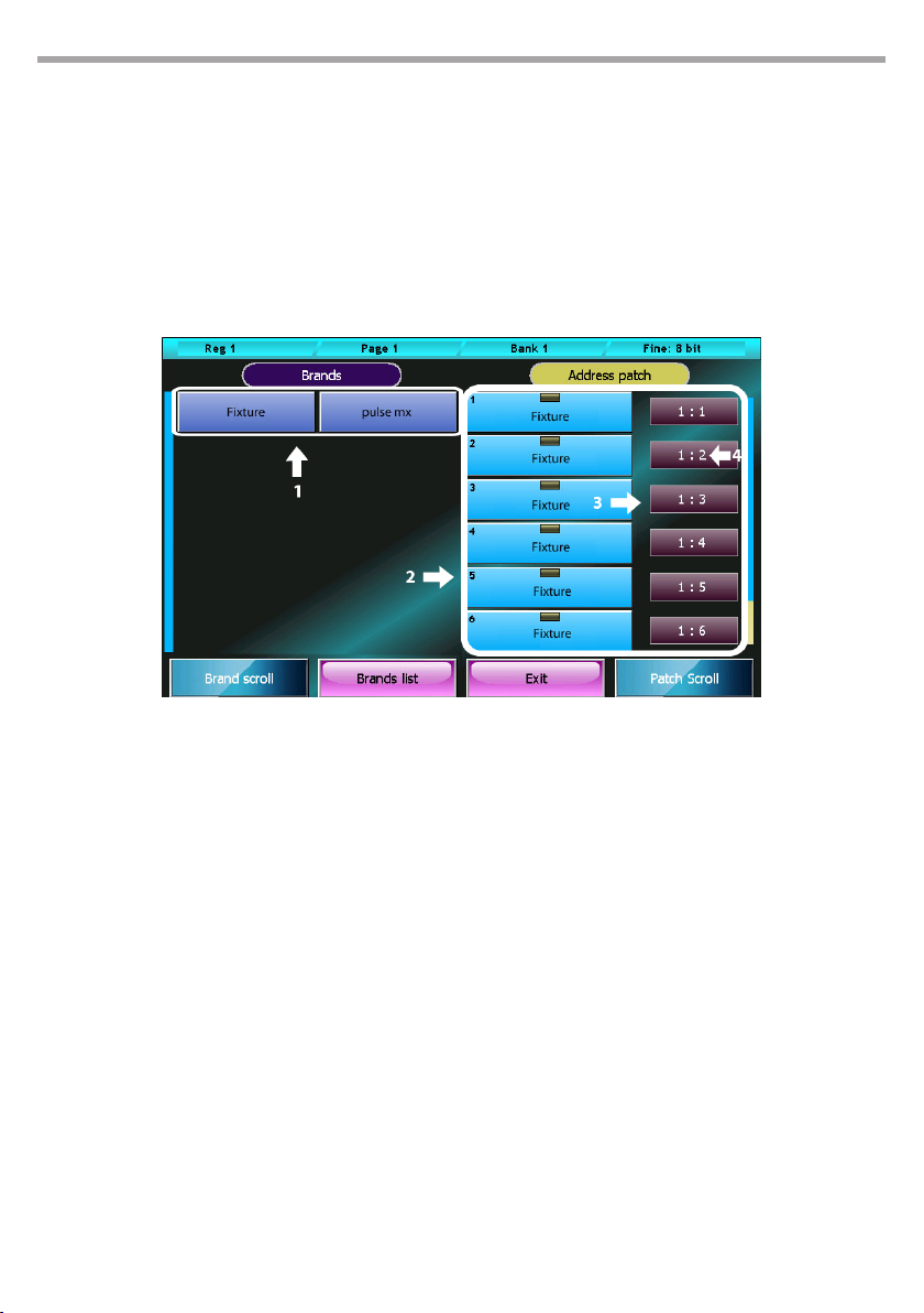
5.1 ADD FIXTURES
The console can manage a maximum of 3072 channels (6 DMX Universes) and, in any case, no more than
1024 xtures.
IMPORTANT: Universe 1 and 2 are also available on the console's xlr connectors, while universe 3, 4 and 5 are
only available on Artnet.
Patch window
The Address Patch button in the Setup menu opens the Patch window, which is divided in two main
parts: one to navigate the xture library and the other to view the list of xtures included in a show.
PULSE MX
Patch window
1. Fixture library browsing area
2. Elenco delle xture inserite nello show
3. DMX universe (valid values are from 1 to 6)
4. DMX start address
Buttons:
• Brand List: Back to the Brand list.
• Exit: Back to Setup menu.
• Pressing one of the brands’ buttons directly display the list of xtures belonging to the corre-
sponding brand.
• Pressing one of the xtures’ buttons directly displays the Add Fixture window allowing to add a
xture to the show.
• The context specic menu in the Patch window contains the following buttons:
• Disable xture: Disable the selected xtures Disabled xtures do not take up any DMX channel
and are not taken into account in any computation; they are easily recognisable, as their address
is displayed in grey font and preceded by an asterisk.
• Enable xture: Opposite to the “disable xture” button, it re-enables the selected xtures. If this
command creates an overlapping, the programme automatically disables some of the xtures
in order to restore a valid conguration, and noties the user of this measure through a specic
message.
• Change Address: Displays the digital numeric keyboard to allow editing the universe and the
DMX address of the selected xtures; type in the value for the universe and for the address, separated by a full stop. If two or more xtures are selected, the programme will assign them consecu-
Fig.37
Page 45
PULSE MX
tive DMX addresses, passing to the following universe if necessary. If the newly assigned address
creates an overlapping, the programme automatically disables some of the xtures in order to
restore a valid conguration, and noties the user of this measure through a specic message.
• Delete: After asking to conrm, this command deletes the selected features from the show. Deletion is nal: it cannot be undone and eliminates all settings for the deleted xtures. This command, however, does not modify in any way the xture library les.
IMPORTANT: if the xture denition le for the show is incorrect, it is necessary to remedy the mistake
through the Fixture conguration programme. Editing the corresponding fdf library le does not have any
eect. In order to apply changes to a library le, it is necessary to erase from the show all corresponding
xtures (thereby losing their programming, including palettes) and subsequently re-insert them.
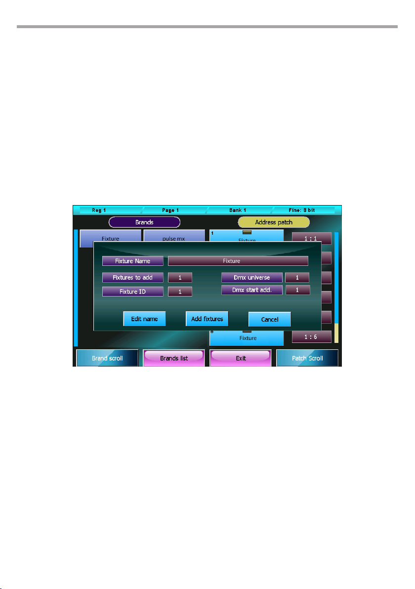
Add fixtures window
Pressing one of the xtures’ buttons in the navigation section of the Patch window displays the Add
xture window.
45
Add Fixtures window Fig.38
Buttons:
• Edit name: opens the digital keyboard allowing to edit the name to be used for a xture during
the show.
• Add xture: this button closes and nalizes the addition of a xture to the show.
• Cancel: this button cancels the operation, closes the Add Fixture window and goes back to the
Patch window.
Wheels:
• Fixture to add: how many xtures of the selected kind must be added to the show.
• Fixture ID: identication number of the xtures to be added. If two or more xtures are being
added, the programme will assign them progressive ID numbers.
• DMX universe: valid values for a DMX universe range from 1 to 6 (both included).
• DMX start add: starting DMX address. If two or more xtures are being added, the programme
will assign them progressive DMX addresses, taking into account the number of channels used by
each xture and passing, if necessary, to the following universe.
IMPORTANT: Universe 1 and 2 are also available on the console's xlr connectors, while universe 3, 4 and 5
are only available on Artnet.
Page 46
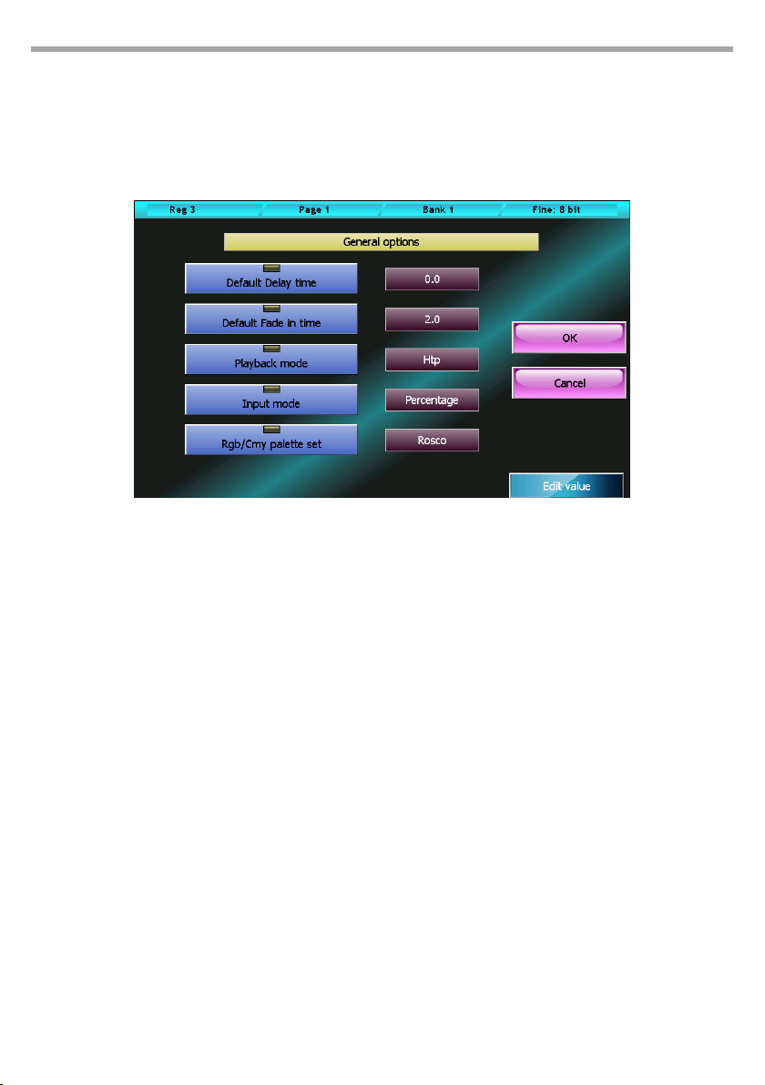
46
5.2 GENERAL OPTIONS
This window allows to edit the console’s general options. To edit a value, select it by pressing one of the
two corresponding buttons and use the fourth wheel.
The OK button saves all changes made and goes back to the Setup menu, while the Cancel button goes
back to the Setup menu without saving any change.
General options window Fig.39
PULSE MX
Default delay time:
Default value of the cue’s delay time. When a new cue is created, it will be assigned this value..
Default fade in time:
Default value of the cue’s fade in time. When a new cue is created, it will be assigned this value.
Stand by time:
Default value of the cue’s stand by time. When a new cue is created, it will be assigned this value.
Playback mode:
Valid values: Htp (highest take precedence) or Ltp (Latest take precedence).. This value aects the
computing criteria applied to the xture’s Htp channel (usually for dimmers).
In Ltp mode, the nal value calculation uses the value of the cue activated most recently, while in Htp
mode the value used is the highest among all the cues aecting the channel.
Input mode:
Valid values: Percentage or Raw. This parameter only aects the way in which the values are displayed. In percentage mode, values are displayed on a per cent basis (from 0 to 100%), while in Raw
mode values are numbers going from 0 to 255 for 8-bit channels, or two values going from 0 to 255
for 16-bit channels.
Rgb/Cmy palette set:
Set of all palettes that can be used in the editor. Valid values: Chris, Gam, Lee, Rosco. The editor
provides the selected palette set to be used with all the xtures having a CMY or RGB color mixing
system.
Page 47
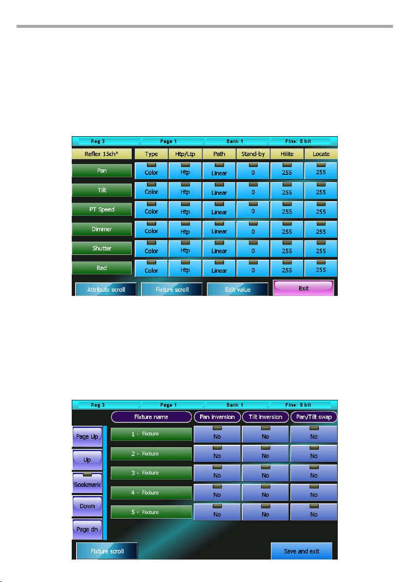
PULSE MX
5.3 FIXTURE CONFIGURATION
This window allows to edit the conguration of all xtures used in the current show. All changes applied
through this function only aect the current show, leaving the xture library unchanged. All changes are
automatically saved, without any conrmation needed. The rst wheel allows too scroll down the list of
features for the currently selected xture. The second wheel allows to select one of the show’s xtures.
To edit a value, it is necessary to select it by pressing the corresponding button and using the third wheel
(Edit value) to set the new value.
The exit button closes the window and goes back to the Setup menu.
47
Fixture conguration window Fig.40
5.4 CONTROLLER CONFIGURATION
See Controllers section.
5.5 PAN/TILT OPTIONS
This window allows to invert and swap the Pan/Tilt functions for each xture used in the show.
Pan/tilt options window Fig.41
Page 48
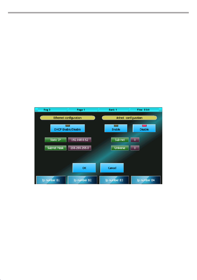
48
The rst wheel, together with the scrolling buttons on the left, allows to scroll down all the show’s xtures which include a Pan/Tilt function.
By clicking the option buttons for each xture, it is possible to separately select the Pan/Tilt inversion
and their swap.
The Save and Exit button saves all data and goes back to the Setup menu. Data are also saved if the window is closed by using the context specic menu or the Edit/Qlist button.
5.6 ARTNET CONFIGURATION
The conguration window for the Ethernet port and the Artnet connector is divided in two parts: the left
part allows to congure the Ethernet port on the console, while the right part allows to congure Artnet.
To edit the Static Ip, Subnet Mask, Sub-net and Universe elds, it is necessary to push the corresponding
button and then use the wheels.
IMPORTANT: the Artnet connector uses a 100Mbit Ethernet connection. It is necessary to verify that the device
connected to the console supports such speed.
PULSE MX
Artnet conguration window Fig.42
Ethernet configuration
DHCP Enable/Disable:
This function can be enabled only if the console is connected to an Ethernet network with a DHCP
server. In this way, the console will automatically acquire the IP number and the subnet mask from
the DHCP server.
Static IP:
If the function DHCP Enable/Disable is enabled, this eld will be ignored. Otherwise, it should be set
accordingly to the other devices connected with the network. While editing this eld, each wheel
modies one octet of the eld.
Subnet Mask:
If the function DHCP Enable/Disable is enabled, this eld will be ignored. Otherwise, it should be set
in accordance with the other devices connected with the network: in general, it is set to 255.0.0.0 or
255.255.255.0 . While editing this eld, each wheel modies one octet of the eld.
Page 49

PULSE MX
The IP number and the subnet mask are each composed of 4 octets ranging from 0 to 255, separated
by a full stop. A simplied rule to assign IP numbers to a network without a DHCP server is as follow:
all devices must have the same octets for the subnet mask 255, while the octets corresponding to the
0s in the subnet mask must form a unique combination for each device.
Artnet configuration
To congure Artnet, simply press the Enable button and set the Sub-Net and Universe values to the same
ones assigned to the Artnet receiver. These two values indicate the rst DMX Universe of the console.
The other 5 DMX Universes are sent through the same Sub-net and the following Universe.
Enable:
Enables/disables Artnet output.
Sub-Net:
Set a value between 0 and 15 accordingly to the receiver connected to the console.
Universe:
Set a value between 0 and 15 accordingly to the receiver connected to the console. This value constitutes the rst of the six DMX Universes transmitted by the console, while the other 5 are sent through
consecutive Universe values.
Certain Artnet systems use the naming Net and Universe, whose validity range is respectively 0-127 and
0-255. In this case, Net must be set to 0, while Universe must equal 16 x SubNet) + Universe.
49
• The OK button saves all changes made and goes back to the Setup menu.
• The Cancel button goes back to the Setup menu without saving any change.
Page 50
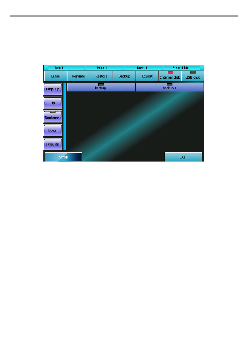
50
5.7 BACKUP/RESTORE
The Backup/Restore window allows to access a number of functions for the managing of copies and for
restoring a show. It is highly recommended to save a copy of the whole show also on an external USB
drive every time a show is modied. This operation, while taking up only a few minutes, can be of vital
importance in case of emergency.
Backstore/restore window Fig.43
Buttons:
PULSE MX
Erase
This button completely erases, after asking to conrm, the selected backup le.
Rename
This button activates the virtual keyboard allowing to rename the selected backup le.
Restore
This button erases, after asking to conrm, the current show and substitutes it with the selected
backup le. All data of the current show is deleted. If necessary, create a backup le for the current
show before launching the Restore command.
Backup
This button copies the current show on the selected disk. Before copying, the digital keyboard is
displayed to type in a name for the new copy. Both the internal disk and a USB drive cannot contain
two backup les with the same name. To avoid this, the programme will ask whether to erase the
pre-existing le or to cancel the operation.
On the USB drive, each backup consists of a folder containing all data concerning the show. The
name of these folders is the same as the one typed in for the backup le. On the USB drive, all backup
les are saved in the “Backup” folder. If the folder does not already exist, the programme will automatically create it.
Export(Import)
This button (which becomes “Import” when the USB drive is selected) allows to copy the current
backup le on the USB drive when the internal disk is selected, and vice versa when the USB drive is
Page 51

PULSE MX
selected. The backup le is copied from one disk to the other without changing its name. If the destination already contains a backup with the same name, the programme will ask whether to replace
it or to cancel the operation.
Internal disk e USB disk
These two buttons allow to select respectively the internal disk and the USB drive. The red LED indicator on the button corresponding to the selected disk will turn on.
Exit
The Exit button goes back to the Setup menu.
51
Page 52
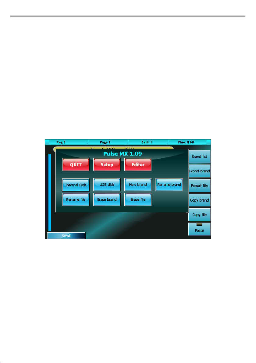
52
5.8 LIBRARY MANAGER
The Exit button goes back to the Setup menu. The xture library is composed of fdf les (xture denition le) and fxr les, which the console uses to avoid displaying all technical details of the xtures
included in the show.
Fdf les are organised in brands or folders, which are in turn located inside the FDFLIB folder. This programme allows to manage this structure through the copy/delete/duplicate functions, both on a singlele basis and on a brand basis.
Library manager displays all brands available on the internal disk. To view the xtures included in a
brand, just push the corresponding button. Pushing the Brand button goes back to the brand list.
To exit the programme, use the context specic menu.
IMPORTANT substituting or deleting a library le does not aect in any way the current show nor the shows
previously created. When a xture is loaded in a show, the console automatically creates a copy of the fdf le
and saves it in the show's data.
To apply the changes made to a library xture, it is necessary to erase from the show all occurrences of that
xture (entailing the loss of their programming) and subsequently reload it.
PULSE MX
Library manager Fig.44
Buttons:
Brand list
Back to brand list display
Export brand (Import brand)
This button (which becomes “Import brand” when the USB drive is selected) allows to copy all les
contained in the current brand from the selected disk to the other disk. The brand is copied without
changing its name. If the destination already contains a brand with the same name, the programme
will ask whether to replace it or to cancel the operation.
Export file (Import brand)
This button (which becomes “Import le” when the USB drive is selected) allows to copy the current
le from the selected disk to the other disk. The backup le is copied from one disk to the other
without changing its name. If the destination already contains a backup with the same name, the
Page 53

PULSE MX
programme will ask whether to replace it or to cancel the operation.
Copy brand
This button is used, together with the Paste button, to perform “Copy and Paste” operations. It saves
the current brand’s path in the internal memory and makes it available for Paste operations. The LED
indicator on the Paste button becomes green to signify that the Paste buer now contains a path.
Copy file
This button is used, together with the Paste button, to perform “Copy and Paste” operations. It saves
the current le’s path in the internal memory and makes it available for Paste operations. The LED
indicator on the Paste button becomes green to signify that the Paste buer now contains a path.
Paste
This button is used, together with the Copy brand and Copy le buttons, to perform “Copy and Paste”
operations. If the LED indicator is turned o, the Paste buer is empty and therefore it cannot be
used. “Copy and Paste” operations are primarily used to move a le from one brand to another or
from one disk to another.
Internal Disk (from the context-specific menu)
Sets the internal disk as current disk and displays the list of available brands.
USB Disk (from the context-specific menu)
Sets the USB drive as current disk and displays the list of available brands.
53
New brand (from the context-specific menu)
Activates the digital keyboard to create a new brand on the current disk.
Rename brand (from the context-specific menu)
Activates the digital keyboard to allow renaming the current brand.
Rename file (from the context-specific menu)
Activates the digital keyboard to allow renaming the current le.
Erase Brand (from the context-specific menu)
Completely erases, after asking to conrm, the current brand and all les contained in it
Page 54
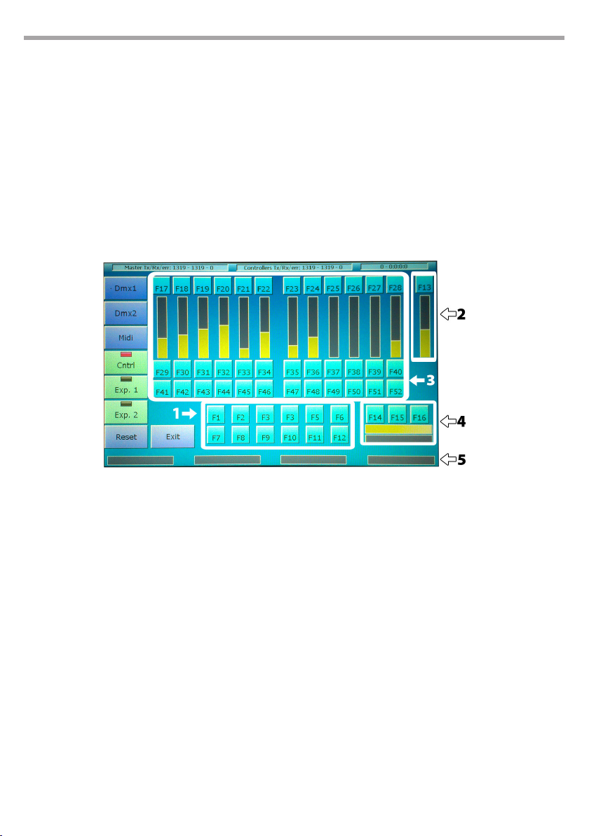
54
5.9 DIAGNOSTIC
IMPORTANT: the diagnostic programme interrupts all processes, including data transfer through DMD and
Artnet outputs.
This programme allows to verify the good functioning of all the consoles’ buttons, sliders, inputs and
outputs.
The diagnostic window displays, through graphical representation, all commands (trackballs, wheels,
sliders and buttons). When any command is activated, the graphical representation on the screen immediately responds, allowing to check whether all command work properly.
The status bar on top shows in real time the data transfer between the console’s internal cards. Data
packets are displayed in the following order: transferred packets, received packets, packets containing
errors. For a correct functioning, the number of transferred packets should be almost identical to that of
received packets, and the number of errors should be lower than 0.1% (1 per mil) of transferred packets.
PULSE MX
Diagnostic
1. Editor keys
2. Grand master and DBO
3. Controllers and playbacks keys
4. Trackball and Pan lock, Fine and Tilt Lock
keys
5. Encoder weels
DMX1 output test
Connect with a male to female DMX cable the DMX1 output with the DMX-in input and press the
DMX1 button: the console will transfer a certain number of data packets through the DMX1 port and
compare them with the data received from the DMX-in input. If the two sets of data match, the test
is considered as a pass; if they do not match, the test is considered as a fail. Obviously, this test also
veries the correct functioning of the DMX-in input.
DMX2 output test
Connect with a male to female DMX cable the DMX1 output with the DMX-in input and press the
DMX2 button: the console will transfer a certain number of data packets through the DMX port and
compare them with the data received from the DMX-in input. If the two sets of data match, the test
is considered as a pass; if they do not match, the test is considered as a fail. Obviously, this test also
veries the correct functioning of the DMX-in input.
Fig.45
Page 55

PULSE MX
The two DMX connectors of each output are internally connected, but in order to make sure that the
wiring works properly, it is advised to verify each port twice, using rst one connector and then the
other.
Midi connection test
Connect with a midi cable the midi-in input to the midi-out output and press the Midi button: the
console will transfer a certain number of data packets through the midi-out port and compare them
with the data received from the midi-in input. If the two sets of data match, the test is considered as a
pass; if they do not match, the test is considered as a fail. This test veries at the same time all Midi-in
and Midi-out ports. No test is available for the Midi-thru port.
Smpte test
To test the Smpte port, simply connect a Smpte generator to the corresponding input on the console. The diagnostic status bar (top right) scrolls the Smpte frames in real time, allowing to verify the
correct reception of the Smpte timecode.
Expansion test 1 and 2
Pressing the buttons Exp.1 and Exp.2 allows to verify the correct functioning of these two expansions. When pressing the button Exp.1, the diagnostic programme receives data from the selected
expansion instead of the internal card of the controllers/playbacks. When expansion commands are
activated, the graphical representation on the screen will respond immediately. Pressing the button
Exp.2 performs the same test on Expansion 2.
Press the Cntrl button to go back to the test of the console’s internal card.
55
Page 56

56
5.10 FIXTURE BUILDER
For each xture included in a show, the console uses a “xture denition le”, called fdf, containing the
information necessary to hide from the user’s view all technical details.
The information necessary for creating an fdf le is:
• number of DMX channels taken up by the xture;
• list of xture’s features and corresponding internal patch;
• any information on commands such as reset, lamp-on, etc.;
• information for inserting predened palettes (value ranges for color wheels or gobos, macro chan-
nels, etc.).
It is not mandatory to insert a palette, the user is free to decide whether to use them or not. Of course, a
xture with a good palette set is easier to use.
IMPORTANT: Each xture is subject to the following restrictions:
Maximum number of parameters: 128
Maximum number of commands: 16
Maximum number of library palettes: 64
Moreover, the total number of features included in the library palettes cannot be higher than 1024.
The next paragraphs contain a step-by-step explanation on how to create a new fdf le.
Parameters window
Open the Fixture builder programme and press the Add parameters button. The number of DMX channels that form the xture has not yet been dened; therefore the digital numeric keyboard will appear,
asking to type in a value. Insert the number of DMX channels for the xture and conrm.
The parameters selection window will open: select the features included in the xture. If the xture includes parameters which are not listed, choose a parameter with a similar function, to be subsequently
renamed.
Use properly the 8-bit and 16-bit buttons to select the size of the feature.
Please remember that this operation does not have to be completed at once; it can be resumed, modied, reduced or expanded at any time.
Once completed, press OK. Next time the parameters window will be opened, all previously set parameters will be displayed.
Data can be edited by clicking on the dierent elds and using the wheels. On the top part of the screen,
the following buttons are displayed: Move up, Move down, Delete Parameter, Rename parameter.
The Add parameter button goes back to the parameter selection window where more parameters can
be added.
PULSE MX
IMPORTANT: please remember to carefully check the Htp/ltp value. Throughout several processes, the console
uses dierent computing algorithms for Htp and Ltp channels, sometimes generating results apparently
unaccountable.
IMPORTANT: please remember to carefully check the Standby, Hilite and Locate values. For obvious reasons,
default values are not always appropriate.
Page 57
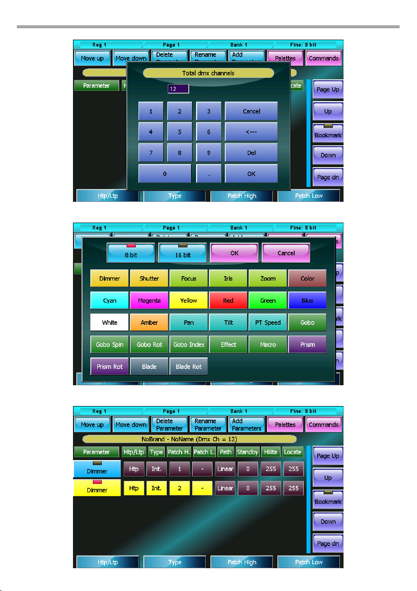
PULSE MX
Insert number of DMX channels Fig.46
57
Parameters selection Fig.47
Parameters window Fig.48
Page 58
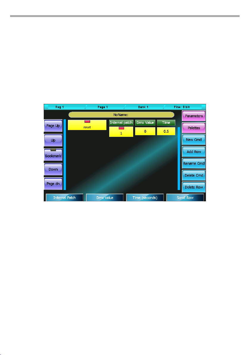
58
Commands window
Once the parameters have been inserted, by pressing the Commands button it possible to insert the
xture commands such as Lamp-on Lamp-o, Motor-reset, etc.
Pressing the New Cmd button allows to add a new command to the list, which at the beginning will be
empty, of course. The command’s values are set using the wheels:
• Internal patch: DMX address for the output of the command value
• DMX value: value to output
• Time: time (in seconds) for which the value has to remain constant during output
More complex commands can be added by inserting more rows of values through the Add row button.
PULSE MX
Commands window Fig.49
The window includes several buttons for editing data:
New Cmd:
Allows to add a new command
Add Row:
Allows to add a new row of values to the selected command
Rename Cmd:
Opens the digital keyboard to rename the selected command
Delete Cmd:
Completely deletes, after asking to conrm, the selected command
Delete Row:
Completely deletes, after asking to conrm, the selected row
Page 59
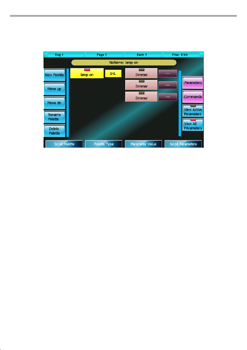
PULSE MX
Palette window
The xture could be now considered as completed, but predened palettes can also be added. In order
to do so, press the Palettes button to open the Palette window.
Palette window Fig.50
The information necessary for inserting a new palette is: name, type, (Int., PT, Color, Gobos, Prism or
Blade) and the state of the features aected by the palette (palette body).
Pressing the New Palette button activates the digital keyboard allowing to type in a name for the
new palette to be created. Afterwards, the palette can be assigned a type and a value for each channel aected, by using the wheels. Channels not aected by the palette must be set to “---”.
59
The window includes several buttons for editing data:
New Palette:
Allows to insert a new palette
Move Up e Move Down:
Moves the selected palette respectively up and down
Rename Palette:
Allows to change the name of a selected palette
Delete Palette:
Permanently delete the current palette, after conrmation
View Active Parameters:
Displays in the palette body only the parameters which are actually involved; oers a compact visualisation of all relevant palette data. To eliminate a parameter of the set of active parameters, set it
to “---”.
View All Parameters:
View all parameters in the palette body- The display mode allow you to add parameters to the set of
parameters used by setting them to a value other than “---”
Page 60

60
Save in library
From the context specic menu, press the Save button. If the xture had already been saved, it will be
simply overwritten. If it is being saved for the rst time a window will open automatically, as in the Library manager, to allow navigating the brands available on the internal disk or on the USB drive. When a
brand is selected, the digital keyboards will appear, asking to type in a name for the xture.
The programme always veries the data inserted, and if an inconsistency is identied, it will display a
diagnostic message. The message can contain two kinds of notication: a warning or an error. Warning
notications signal an unusual yet valid situation (e.g. not all DMX channels are occupied by a parameter). The user can decide whether to cancel the command and properly edit the xture or to go on
saving. Error warnings signify invalid situations and must be corrected before saving (e.g. two features
sharing the same internal patch).
Editing a fixture already included in the library
IMPORTANT: editing a library le does not aect in any way the current show nor the shows previously saved
on disk, as for each show its data is saved in the xture information.
It is often necessary to edit an existing xture, or it can be easier to create a new xture basing on an
existing one rather than starting from scratch. From the context specic menu, press Open: a window
will appear, allowing to navigate the brands available on the internal disk or on the USB drive. As in the
Library manager, a le can be selected and displayed or edited.
Pressing the Edit DMX Ch button from the context specic menu allows to change the number of channels taken up by the xture. All other data concerning the xture is directly available for display and
editing in the Parameters, Commands and Palettes windows.
PULSE MX
After editing as needed, the older xture version on the disk can be overwritten by pressing the Save
button in the context specic menu. To save the xture under a new name and/or with another brand,
select Save As.
IMPORTANT: fxr les (recognisable from the "*" character at the end of their name) can be read but cannot be
written, and therefore cannot be edited. It is possible, though, to open an fxr le and then save it as an fdf le.
Page 61
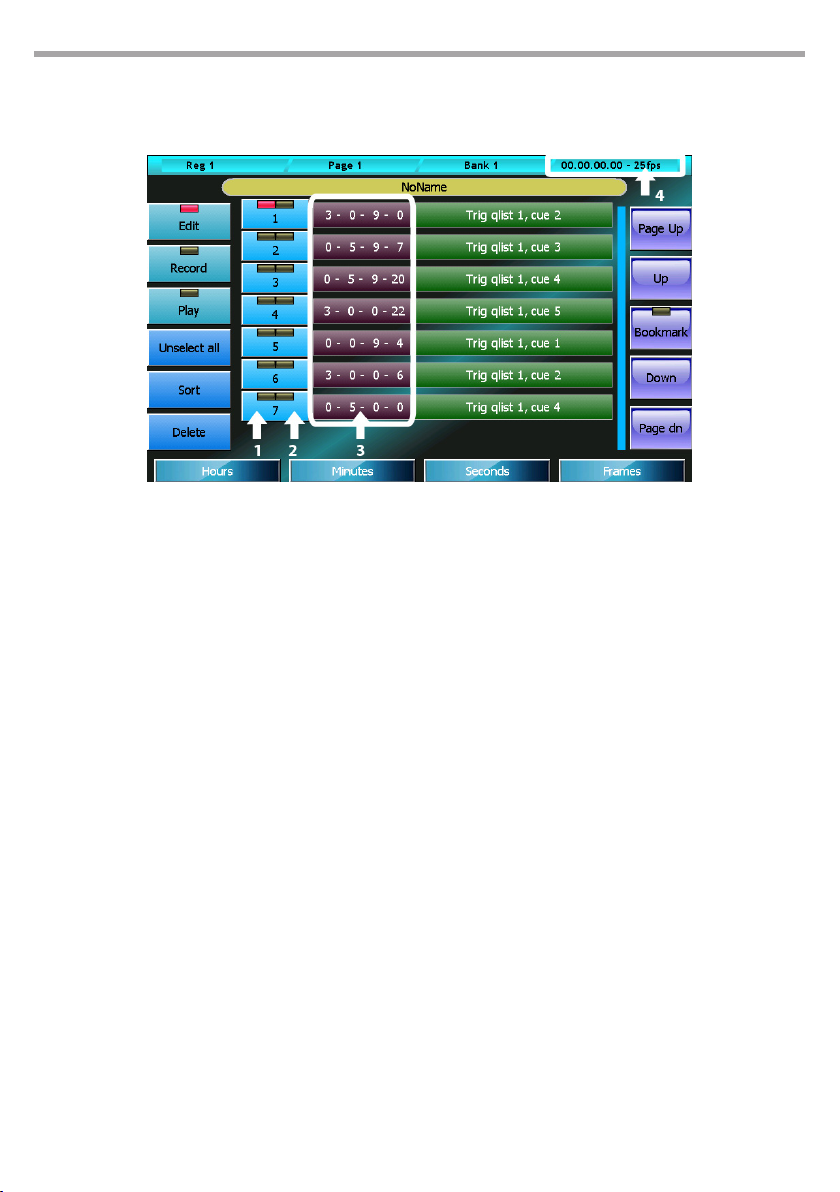
PULSE MX
Context-specific menu
The Context specic menu is the same in all of the three windows.
Context-specic menu Fig.51
Buttons:
New:
Resets all programme data and prepares to create a new xture denition le
61
Open:
Opens the browser to allow loading an existing fxr or fdf le
Save:
Saves all changes made to the current le
Save As:
Opens the digital keyboard to save another copy of the current le under a new name
Edit DMX Ch:
Allows to change the number of DMX channels of the xture
Page 62
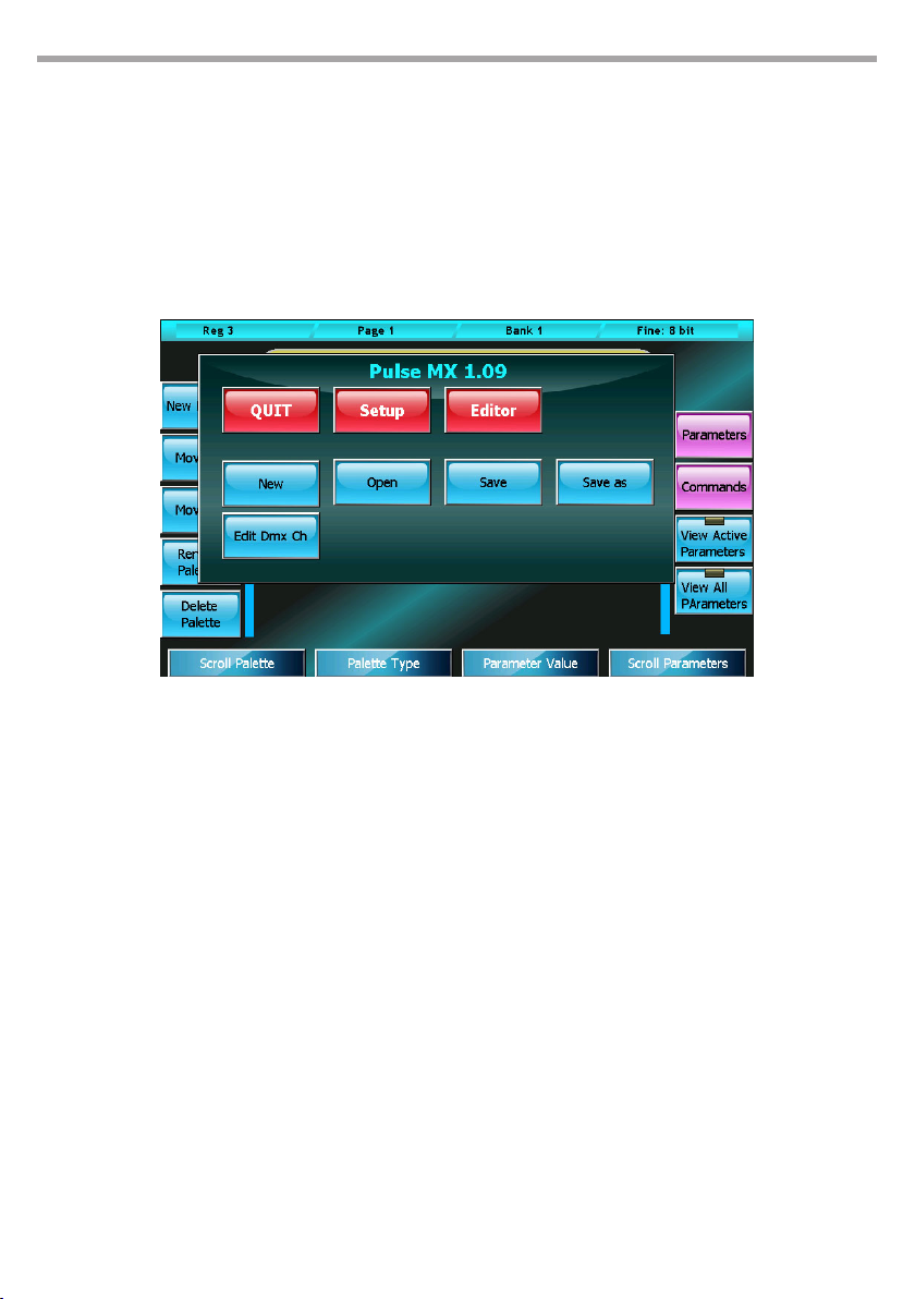
62
PULSE MX
- 6 - SMPTE TIMECODE
The SMPTE timecode is a signal which contains a time identication in the hours:minutes:seconds frame
format; it was invented in the cinematographic industry to synchronise audio and video and is ideal for
solving general synchronisation problems.
The console is capable of receiving a SMPTE signal generated by a SMPTE master (the device which
stores the reference clock for synchronisation) and activating certain events at predened times.
Smpte window
1. Selection led: O=not selected event,
Red=selected event
2. Trigger led: Green=triggered event, O=not
triggered event
3. Event activation times in Hours-Minuts-seconds-
Frames
4. Real time smpte clock
Buttons:
Edit:
puts the list in edit mode. When the Edit button is active, you can edit the list eliminating or editing
the activation times of single events.
Record:
puts the list in record mode. When the Record button is active, all the events which occur in the console are added to the list (limited to the types recognised by the programme)
Play:
puts the list in play mode. When the Play button is active, each event is compared against the smpte
time and potentially activated.
Unselect all:
deselects all events (valid only in Edit mode)
Fig.52
Page 63
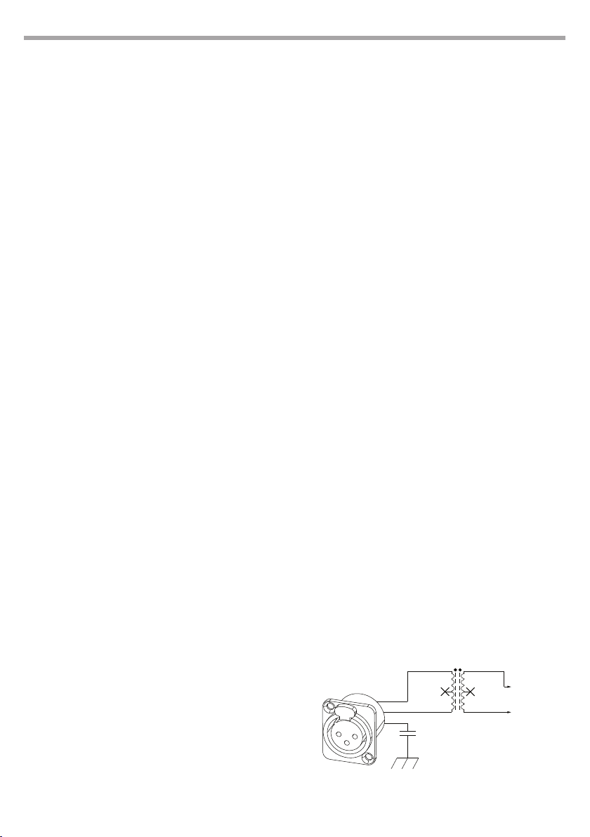
PULSE MX
63
Sort:
tidies the list of events based on a growing smpte times (valid only in Edit mode)
Delete:
deletes, after conrmation, all selected events (valid only in Edit mode)
New (from the context-specic Menu) Deletes the current list and prepares for the creation of a new
list.
Save as (from the context-specific Menu):
saves (duplicates) the current list under a new name
Open: (from the context-specific Menu):
opens the browser to load a list which had previously been saved on the disk.
IMPORTANT: before putting a list in the play status make sure it is tidy; otherwise, press the Sort button; if
the list is not tidy, the correct execution of events is not guaranteed. Play status is maintained even after
exiting the Smpte window.
Creating a list of events
When the Smpte window is in Record mode, any event generated by the console (for example, sending
a trigger to a playback) is added to the queue of Smpte events in a new line. If the Smpte source is not
connected, the new event has 0-0-0-0 activation time; the Smpte source is connected, the activation
time is read by the Smpte timecode:
• Cue trigger
• Cue list release
• Release of all Qlists
• Change page
Usually the Record stage is followed by an Edit stage during which the activation times are amended and
it is often necessary to return to the Record mode in order to add any missing events.
Execution of the list of events
To execute the list of events, set it to Play mode. In order for the list to be correctly processed, it has to be
in the right chronoplaybackical order: the Sort button, when the list is in Edit mode, serves this purpose.
In Play mode, the received timecode is constantly compared against the events on the list which are
activated when necessary.
SMPTE INPUT SECTION
2
3
1
CHASSIS
Audio transformer
To SMPTE
TY-141P
ln
After connecting, verify
that the Smpte frames
are scrolling on the status
bar in the top right-hand
corner of the Smpte
window.
Receiver
Smpte Connection
The Smpte input of the console is made up of an
audio transformer connected to pins 2 and 3 of the
XLR connector (See picture below) and is suitable
for directly connecting a Smpte device with dierential output. The galvanically isolated structure of
the input allows to use a Smpte source with a singleended output by connecting the hot wire and the
signal mass respectively to pins 2 and 3 of the XLR
connector.
2
1
3
SMPTE input section schematic
Page 64

64
PULSE MX
- 7 - MIDI INTERFACE
The main playback functions of the console can be controlled by MIDI comunication protocol; this can
be usefull for controlling and/or syncronizing the console playback by any device capable of trasmitting
Midi messages.
The playback functions controllable by Midi protocol are:
1. Cue list activation
2. Cue list release
3. Cue List ash activation
4. Cue List ash deactivation
5. Cue list intensity submaster setting
6. Cue list eect speed master setting
7. Cue list eect size master setting
8. Page change
Before exploring how the Midi conguration window works we will talk a little bit about Midi messages
structure: a Midi message has 2 or 3 bytes depending on message type; the rst byte, called Midi status
byte, contains both the message type (Note On , Note O,..) and the channel number; the following
bytes, called Midi data bytes, have dierent names and meanings depending on message type and their
value can range from 0 to 127. In order to control the console playback functions it is necessary to assign
a Midi status byte to each of them; the available messages for console playback control are:
• Note O: 3 bytes, followed by Note number and velocity
• Note On: 3 bytes, followed by Note number and vel0city
• Control Change: 3 bytes, followed by Control number and New value
• Program Change: 2 bytes, followed by New program
NOTE: by convention it is assumed that a Note On message with zero velocity is interpreted as Note O
Due to its features, the Program Change message cannot be used to control the master setting functions
(functions 5,6 and 7).
MIDI Configuration
The Midi conguration window can be opened by pressing the Midi conguration button from Setup
Menu.
First of all you have to dene which cannel Midi messages directed to the console will be transmitted on:
you can set this value by moving the rst wheel; if you select All, the console will receive all Midi messages regardless of the channel number which they are transmitted on.
Then you have to select the specic Midi message that will manage each functions. In order to do this
you have to move the second and third wheel for selecting respectively the message type (Midi status
byte) and the starting value for the rst Midi data byte (Midi start value).
The rst Midi data byte value represents the number of Cue list involved by the function; this number is
obtained by making the dierence between the Midi data byte value and the Midi start value, if the difference is null the current cue will be selected.
In this way a range of 25 values for each function will be reserved except for the Change page command
that require only 24 values to address all the pages because the destination page number is calculated
as the dierence above mentioned plus 1.
The Playback level, Eect speed and Eect size commands need 3 bytes messages in order to be completely dened (thus they cannot be managed by the Program change message that has 2 bytes only),
the rst Midi data byte contains the Cue list number (using the same convention already pointed out on
previous paragraph) and the second Midi data byte contains the master value information coded in two
dierent way depending on the command:
Page 65
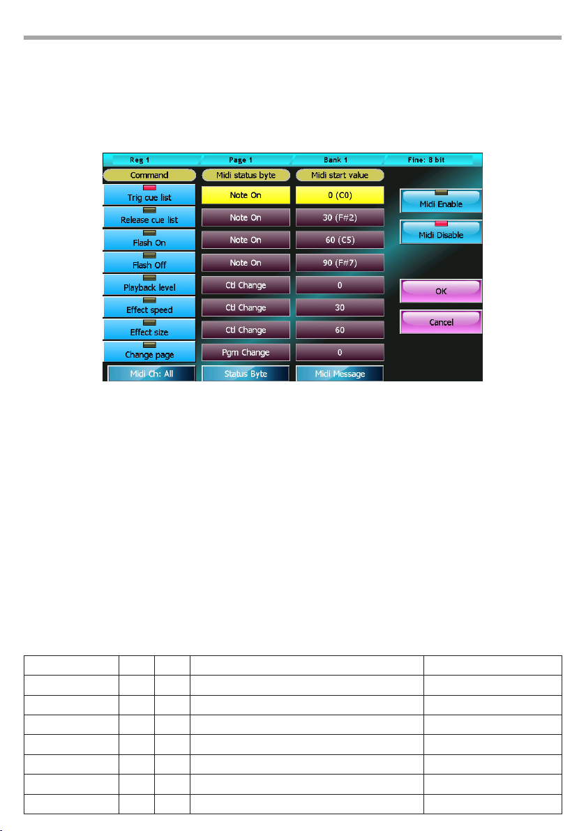
PULSE MX
• Playback level: the level is expressed as percentage; if the value is above 100 will be interpreted as
100%
• Eect size and Eect speed: the level is expressed in step of 4 percentage points, so that the value
25 stands for 100%, the value 127 (that is the maximun value allowed for midi data bytes) stands for
508%
Midi conguration window Fig.53
65
Buttons:
Midi Enable
Enables the Midi protocol processing
Mdi Disable
Disables the Midi protocol processing
OK
Saves all changes and goes back to the Setup menu
Cancel
Goes back to the Setup menu without saving any change
Some examples that refer to the conguration showed on above picture:
Midi Status byte Byte 1 Byte 2 Operation Note
Note On 0 nn Trigs the current cue list nn must be dierent from 0
Note On 4 nn Trigs the cue list number 4 nn must be dierent from 0
Note On 38 nn Releases the cue list number 8 nn must be dierent from 0
Control Change 10 50 Sets the submaster level of cue list 10 to 50%
Control Change 40 50 Sets the master speed level of cue list 10 to 200%
Control Change 71 20 Sets the master size of cue list 11 to 80%
Program Change 11 -- Set the page 11 as the current page
Page 66
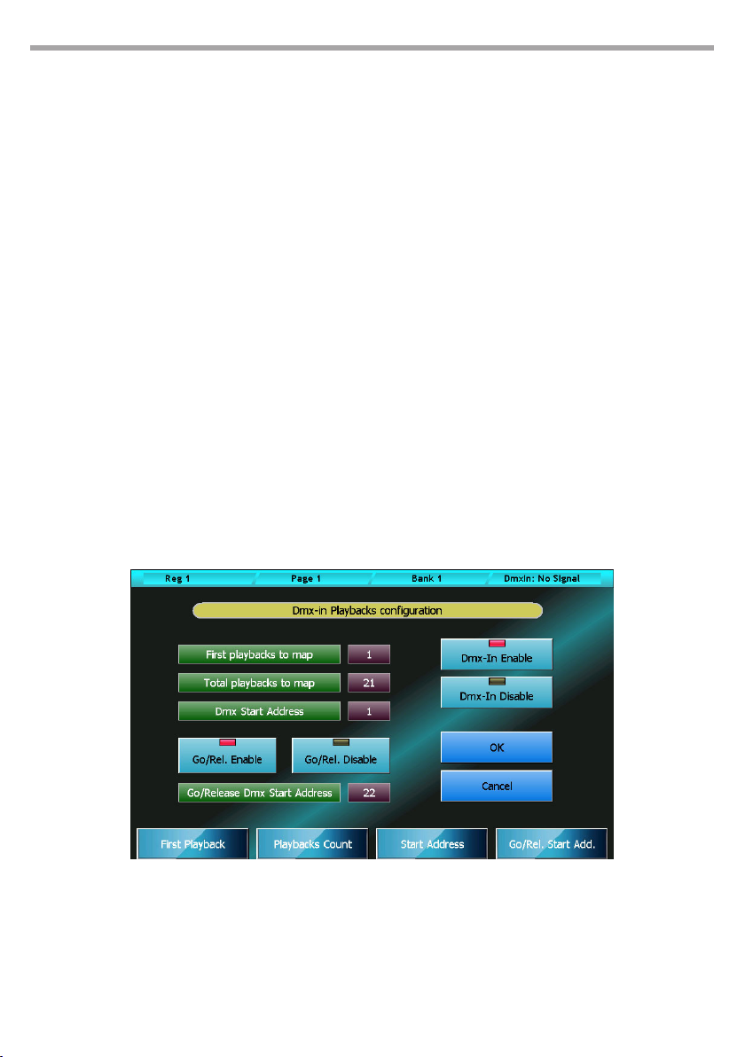
66
PULSE MX
- 8 - DMX-IN INPUT
The DMX input allows you to connect a generic DMX device as a console expansion and control all playbacks and up to 288 manual-cues through device sliders.
Two programs are provided in order to congure both features.
IMPORTANT: Please connect the DMX device or switch it on only when the console is up and running, otherwise
the console will not recognize the device.
Remote playbacks configuration
The remote playback control by DMX input you allows to manage the console playbacks through a generic device capable of transmitting DMX data, keeping the built-in sliders free for other pourpose as
Controller or group masters.
You can send Trigger and Release commands to console registers and control their intensity master
using two DMX channels per playback. The use of one DMX channel for sending triggers and Release
commands is optional.
The DMX-In Playbacks Conguration window can be opened by pressing the homonymous button from
Setup Menu.
On the status bar, on the top-right corner, you can see the DMX input status: if the DMX input is not connected or no DMX data are transmitted the “DMX-In: no signal” message will be displayed, otherwise
three numbers will be showed that mean: the receiver status (1 stands for receiver on), the number of
received data packets and the number of transmission errors. The last two numbers are reset to zero
every time the conguration window is opened.
You can change all the conguration values by moving the wheels.
DMX-IN Playbacks Conguration window Fig.54
Window buttons and fields:
DMX-In Enable
DMX playbacks control global enable
Page 67

PULSE MX
DMX-In Disable
DMX playbacks control global disable. If this button is on, the console will ignore all the rest of the
conguration and the playbacks control by DMX input is inhibited.
Go/Rel. Enable
Trigger and Release receive command enable. Two DMX channels for each DMX controlled playback
are used if this button is selected.
Go/Rel. Disable
Trigger and Release receive command disable . Only the intensity master of playbacks is controlled
if this button is selected
OK
If the new conguration is error free, it will be activated and saved on the disk and the conguration
window will be closed, otherwise an error message will appear.
Cancel
It aborts all the changes made and goes back to the Setup Menu.
First playback to map
This is the rst playback that you will control by the external DMX device. You can control up to 24
Playbacks.
Total playbacks to map
This value is the total number of playbacks that will be controlled by the external DMX device. Since
you can control the playbacks ranging from 1 to 24, the sum of First Playback To Map and Total playbacks to map elds has to be not above 25
67
DMX Start Address
This is the rst of the n DMX channels used to control the playbacks intensity master (with n equal
to the Total playbacks to map value)
Go/Release DMX Start Address
This is the rst of the n DMX channels used to send Trigger and release commands to playbacks (with
n equal to the Total playbacks to map value)
Using the DMX channel that controls the playbacks intensity master is useful to address the cue
storing: If you move a slider after pressing the Store key, the cue will be saved on the register controlled by the slider moved.
The Go/Release channel works in the following way:
• A trigger will be sent to the playback when the channel reach 100%
• When the channel value goes down to 0% a release command is sent.
If you use a console having sliders and ash buttons you can set the sliders position at about 50%
and use ash keys for to send triggers and move down the sliders to 0% to send Release commands
IMPORTANT: The DMX remote playbacks control has priority over built-in controllers. If the same playback
is congurated in order to be controlled by a built in slider and by an external DMX device, the DMX device
will take precedence and the built-in slider will be disabled.
Page 68
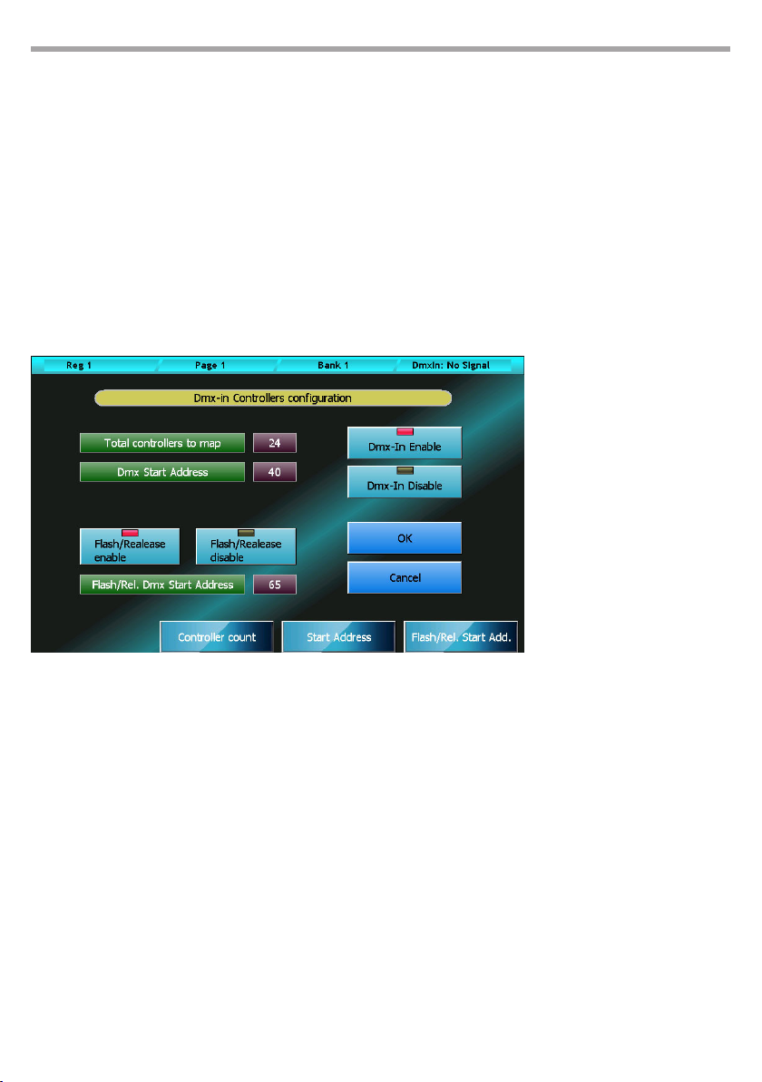
68
PULSE MX
Remote controller configuration
This feature allows you to control by an external DMX device up to 288 manual cues that means you can
have all the cues of all the console banks on your nger tips.
One or two channels can be used to control each manual cue: one channel is used to control manual cue
slider and the other one is used to manage the ash and release commands.
The DMX-In Controllers Conguration window can be opened by pressing the homonymous button
from Setup Menu.
On the status bar, on the top-right corner, you can see the DMX input status: if the DMX input is not connected or no DMX data are transmitted the “DMX-In: no signal” message will be displayed, otherwise
three numbers will be showed that mean: the receiver status (1 stands for receiver on), the number of
received data packets and the number of transmission errors. The last two numbers are reset to zero
every time the conguration window is opened.
You can change all the conguration values by moving the wheels.
The conguration showed on
the left means that the rst 48
channels of the external DMX
device are used to control only
the sliders of 48 manual cues.
Finestra DMX-In Controllers Conguration
Fig.55
Window buttons and fields:
DMX-In Enable
DMX manual cue control global enable
DMX-In Disable
DMX manual cue control global disable. If this button is on, the console will ignore all the rest of the
conguration and the manual cue control by DMX input is inhibited.
Flash/Rel. Enable
Flash and Release receive command enable. Two DMX channels for each DMX controlled manual
cue are used if this button is selected.
Flash/Rel. Disable
Flash and Release receive command disable . Only the slider of manual cue is controlled if this button is selected
Page 69

PULSE MX
OK
If the new conguration is error free, it will be activated and saved on the disk and the conguration
window will be closed, otherwise an error message will appear.
Cancel
It aborts all the changes made and goes back to the Setup Menu.
Total controllers to map
This value is the total number of manual cues that will be controlled by the external DMX device. You
can control up to 288 manual cues that means all the manual cues of all the console banks.
DMX Start Address
This is the rst of the n DMX channels used to control the manual cue sliders (with n equal to the Total
Controllers to map value)
Flash/Release DMX Start Address
This is the rst of the n DMX channels used to ash and send release commands to controllers (with
n equal to the Total Controller s to map value)
Using the DMX channel that controls the manual cue sliders is useful to address the manual cue
storing : if you move a slider after pressing the Store key, the scene will be saved on the manual cue
controlled by the slider moved.
The Flash/Release channel works in the following way:
• Reaching 100% is equivalent to bring the manual cue slider at 100%
• When the channel value goes down to 0% a release command is sent.
69
IMPORTANT: if you enable the manual cues remote control by DMX, all the controllers congurated as
manual cues are changed in playbacks masters and the control of all manual cues is moved to the extern
DMX device.
Page 70
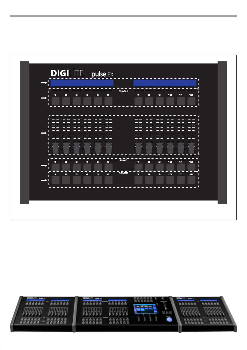
70
PULSE EX
- 9 - EXPANSION
9.1 OPERATING ELEMENTS AND CONNECTIONS
1
2
3
4
5
Front panel
1. PLAYBACK STATUS
2. FLASH KEYS
3. INTENSITY MASTER
4. TRIGGER KEYS
5. SELECT/PAUSE KEYS
It is possible to connect up to maximum two expansions per console.
Fig.56
Fig.57
Page 71

PULSE EX
9.2 CONNECTION TO THE CONSOLE
The expansion is connected to the console via the single cable provided (6 pin phone cable with a “pin
to pin” connection) and does not require a power cable. Connecting is very easy:
• Make sure that the console is switched o
• Connect the connection cable between the Exp.1 (or Exp.2) switch and the socket on the rear panel
• Switch on the console
It is possible to connect up to maximum two expansions per console.
IMPORTANT: connect the expansion to the console exclusively using the cable provided. The use of unsuitable
cables may cause permanent damage to the expansion.
9.3 HOW THE EXPANSION WORKS
Each expansion gives the operator an extra 12 playbacks. Each playback is made up of a cursor potentiometer and three keys.
It is a fully congured system with two expansions capable of transmitting 48 cue lists contemporaneously: 24 are controlled by the console playbacks and 24 are controlled by the playbacks of the two
expansions.
Page organisation
The connection of the expansions does not modify the amplitude of the pages of the console which
continue to contain 24 cue lists each; the presence of expansions simply allows you to control two pages
at the same time: the current page thanks to the console playbacks and the following page through the
expansions. If only one expansion were connected, this would allow you to control the rst 6 cue lists of
the following page.
To use the expansions as conveniently as possible, we recommend always setting the current page on an
even page; this way, even pages are on console playbacks and odd pages are on expansions
The advantage of this type of organisation consists in being able to easily access all cue lists of a show
designed and prepared for the use of expansions even when these are not present.
71
Sliders and keys
Each expansion controls 12 playbacks, each of which has 3 keys and a slider. The slider is the cue list’s
master of intensity, that is to say it reduces all HTP channels controlled by the cue list.
The key above the slider performs the playback’s ash function: when you press it, it instantly sets the
slider value at 100% and keeps it that way for as long as it is pressed.
The trigger key, located right under the slider, is the equivalent of the console’s playback key: when
pressed, it activates the rst cue on the cue list contained in the playback or it activates the following cue
if the cue list had already been activated (Go function). It can be used together with the Release e Select
keys, respectively to release and select the cue list.
The selection/pause key, located in the rst row of keys at the bottom, has two dierent task, depending
on whether the cue list is on or o. If the cue list is o, it is used to select the current playback (without
having to use the Select button).
When the cue list is active, it transforms into a play/pause key: when pressed once, it “freezes” any ongoing eects or fade-ins and fade-outs; when pressed a second time, it “unfreezes” the evolution of the
cue which starts again from where it had been suspended.
Page 72

72
PULSE
- 10 - APPENDIX
10.1 GLOSSARY
Attribute (or Parameter): every single function of a xture which is controllable via DMX or Artnet such
as: dimmers, pan, tilt, color wheel, gobo wheel, etc.
Bank: a group of 12 manual cues associated to as many controllers. It is possible to store up to 288
manual cues arranged in 24 banks containing 12 manual cues each.
Button: GUI element to press in order to activate the corresponding function. It diers from the switch
which is an actual key of the console.
Controller: Controller: an entity consisting of a slider and a freely congurable key: playback master,
group master or manual cue
Cue: denes the status of an array of attributes; It is often referred to as ‘Scene’ or ‘Memory’
Cue-list: an ordered set of cues, also referred to as Qlist
Cue-list timing (o timing): a set of values which dene the timing behaviour of the Qlist and of indi-
vidual cues
Editor: a programme that allows access to the parameters of the show’s xtures. It is used to create and
edit cues and palettes. The editor has priority over all playback functions
Empty: status was not assigned to an attribute. When you save a cue, only the assigned attributes are
saved and the Empty attributes are disregarded.
Fixture: a generic term for any projector or device connected to the console via DMX or Artnet and
controlled by the latter
Manual cue: cue to be associated to a controller; unlike standard cues, it does not have timing or eects
Page: group of 24 cue-lists associated to the 24 Playbacks on the console. By changing page, a new set
of 24 cue-lists will be associated to the playbacks
Palette: status of one or more attributes related to one or more xtures to be conveniently used for creating cues. Updating a palette entails automatically upgrading all cues involved.
Playback: a feature which allows you to control a cue-list. A cue-list can be saved, edited and aired only
if it is associated with a playback. It can consist of a single key or two keys and a slider if internal (depending on the conguration of the console) or of three keys and a slider if these belong to the expansion.
Parameter: see Attribute
Switch (or Key): physical interface button.
Key: see Switch
Trigger: event which determines the activation of a cue.
Page 73

Page 74

Page 75

Page 76

DIGILITE
Via Appia, km 136,200 - 04020 Itri (LT) - ITALY
Phone +39 0771 721966 - Fax +39 0771 721977
www.digilite.eu - email: [email protected]
DIGILITE is a brand distributed by the company Music & Lights S.r.l.
digilite.eu
 Loading...