

Digilin LDMX-PWM-3 User Manual
Document R e v : 1 . 6 digilin.co m . a u
6 May 2 0 1 3 37 Oxfor d S t
Bulim b a , Q l d 4171
Australia
Ph +6 1 7 3 8 9 9 1267
Fax +617 3 8 9 9 1261
© 2 0 1 3 D i g ilin A u s t r a l i a . C o l o u r T h e m e C o n t r o l ler i s a t r ademark o f D i g i l i n
Au st r a l i a . P r o d u c t s p e c i f i c a t i o n s a r e s u b j e c t t o ch an ge wi t h o u t no t i c e .
User Manual
DMX Receiver with 3 Channel
PWM Driver
LDMX-PWM-3
Safety Notes
Install i n a dry, v e n t i lated area.
Indoor use o n l y
!
User Manual
DMX Receiv e r with 3 C hannel PW M D r i v er
6 May 201 3
dig i l i n . c o m . a u P a g e 2 o f 9
Table Of Contents
Introduction ............................................................................................................... 2
Specifications ............................................................................................................ 3
Physical ................................................................................................................. 3
Inputs .................................................................................................................... 3
Outputs .................................................................................................................. 3
Installation ................................................................................................................ 3
Connections ........................................................................................................... 3
Operation .................................................................................................................. 3
Setting Address ..................................................................................................... 3
Using With Colour Theme Input ............................................................................ 4
Using With DMX Input ......................................................................................... 4
Test Mode ............................................................................................................. 4
Fallback Output ..................................................................................................... 4
Appendix A. DIP Switch Settings .............................................................................. 5
Appendix B. Interconnection Detail Drawing ............................................................ 9
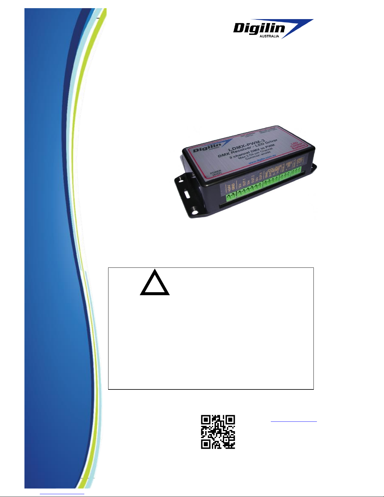
Introduction
The LDMX-PWM-3
(Figure 1) is a DMX
receiver with three channels
of PWM driven outputs for
controlling constant current
LED fittings, such as
Digilin’s RGB Taipan or
Constant Current Linear
Light Strips. The PWM
outputs make use of
Digilin’s special smoothed
PWM transitions software
making variations in light
output almost imperceptible even at low levels. In addition to DMX input, the
LDMX-PWM-3 also has a connector for direct interfacing to Digilin’s Colour Theme
Controller, making a complete system simple to install and control.
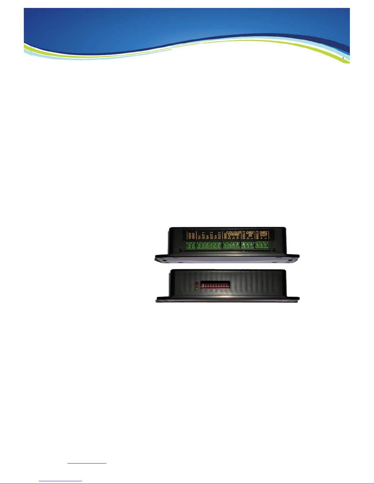
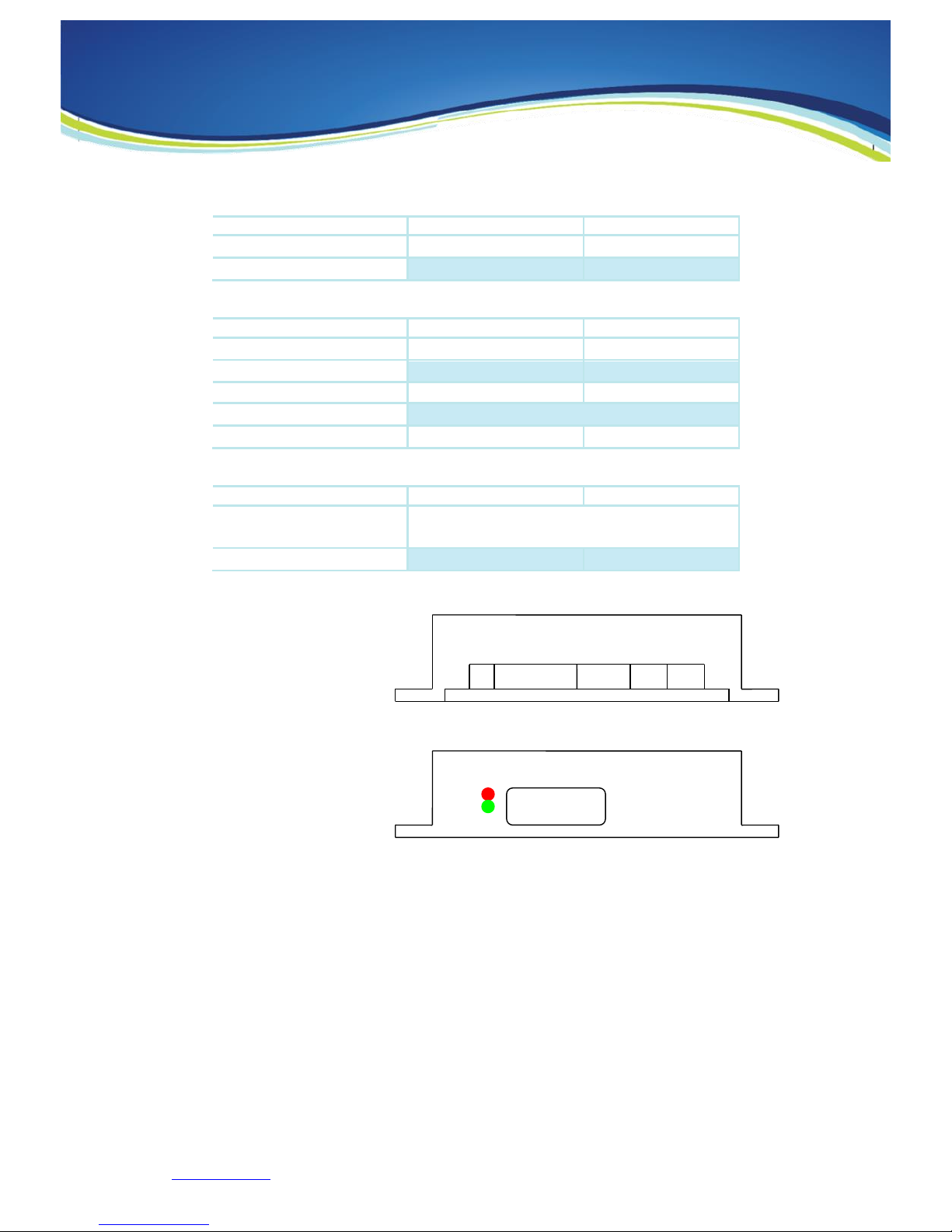
Power
DMX activity
DMX Address
1 2 3 4 5 6 7 8 9 10
Figure 1 Front and rear view of the LDM-PWM-3.
User Manual
DMX Receiv e r with 3 C hannel PW M D r i v er
6 May 201 3
dig i l i n . c o m . a u P a g e 3 o f 9
Specifications
Physical
Units
Dimensions
138 x 63 x 31
mm
Weight
115
g
Inpu ts
Units
Voltage
12 – 24
VDC
Current
6
A
Fuse
Communications
DMX or Colour Theme Controller
DMX Load
0.25
Standard Devices
Outp uts
Units
Outputs
3 Channels Common Anode (low side)
PWM
Current Per Channel
2
A
Installation
Conn ectio ns
Figure 2 shows the
connections on the LDMXPWM-3. For standard
operation, simply connect
24V to the power connector,
the led fittings to the PWM
outputs and either the Colour
Theme Controller or a DMX
source to control the light
levels.
Operation
The LDMX-PWM-3 has a single 24VDC power supply. Once it is connected, the red
power LED shown in Figure 2 will come on. If the unit is receiving good
communications, the green DMX activity LED will also be on.
Setti ng Addr ess
The DMX address is set using the first 9 switches of the DMX address switch. The
address is set as a binary number (with switch 1 the LSB, Appendix A lists addresses
and their corresponding switch settings). As the unit is a 3 channel receiver, it will
respond to data in the set address, and the following 2 addresses in the DMX data
stream. Therefore, the address should not be set to over 510. Note: that to use a
Colour Theme Controller, the address must be set to 1.
Figure 2 Connection diagram.
+24V
GND
V+
Out1
V+
Out2
V+
Out3
GND
Data+
Data-
V+
Shield
DMX+
DMX-
Shield
DMX+
DMX-
Power
DMX
DMX Address
1 2 3 4 5 6 7 8 9 10
 Loading...