

Page 1
XX--BBooaarrdd RReeffeerreennccee MMaannuuaall
PPrroodduucceedd iinn CCooooppeerraattiioonn wwiitthh XXiilliinnxx,, IInncc..
Revision: January 2, 2007 215 E Main Suite D | Pullman, WA 99163
www.digilentinc.com
(509) 334 6306 Voice and Fax
Overview
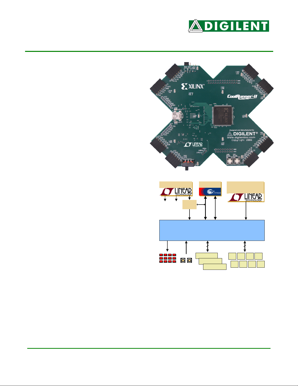
The X-Board is a complete circuit development
platform for Xilinx’s CoolRunner
TM
-II CPLD. It
provides all essential support circuits for the
CoolRunner-II, so users can focus on creating
and downloading new designs. An on-board
USB2 port supplies power to the board and
provides a data port for CPLD configuration as
well as user data transfers.
More than 75 CPLD signals are routed to
expansion connectors so designs can easily be
extended. Thirty-two signals are routed to 6-pin
connectors that can accommodate Digilent’s
Pmod I/O modules – Pmods are small, low-cost
accessory boards offering circuits like A/D and
D/A converters, various I/O ports, and highcurrent outputs for motor drivers, etc.
X-Board features include:
Power Supplies
USB2 Port
Silicon Oscillator
(1000/100/10KHz)
• A 256 macrocell CoolRunner-II CPLD
in a TQ-144 package
• An on-board USB2 port for JTAG
programming and user-data transfers
3V3
USB
3V3
I/O
Current
Meter
1V8
JTAG
USER DATA
• An on-board 16-bit A/D converter to
measure real-time CPLD current during
Xilinx CoolRunner2 XC2C256-TQ144
board operation (data is sent to the PC
for display via the USB cable)
• An user-settable silicon oscillator
(1000/100/10 KHz), plus pads for a
second crystal oscillator
• 12 LEDs and two pushbuttons for
on-board I/O
12 LEDs
2 buttons
40
J9 (26 pin)
J10 (16 pin)
J12 (6 pin)
General Purpose
Connectors
J1
For A/D & D/A converters,
32
J2 J3 J4
J5 J6 J7 J8
6-pin connectors
motor drivers, etc.
Functional Description
The X-Board provides an inexpensive, robust, and easy-to-use platform that anyone can use to gain
experience with the latest CPLD devices and modern design methods. It is centered on the
CoolRunner-II CPLD, and it contains all needed support circuits so designs can get up and running
quickly. The X-Board is an ideal introductory platform for experimenting with new designs or learning
about CPLDs and CAD tools. The large collection of expansion connectors allow designs to grow
beyond the X-Board, either with user-designed boards or breadboards and/or peripheral module
(Pmod) boards offered by Digilent.
®
6 pages Doc: 502-107
© 2007 Digilent, Inc. All rights reserved. DIGILENT and the Digilent logo are trademarks of Digilent, Inc. XILINX, and the Xilinx and
CoolRunner-II logos are trademarks of Xilinx. Other product and company names mentioned may be trademarks of their respective owners.
Page 2

X-Board Reference Manual
Digilent
www.digilentinc.com
Software Installation
We recommend installing the Digilent Adept software prior to connecting the board to the PC. This
allows the drivers to be installed that will allow Windows XP to recognize the device. At this time
Windows is the only supported operating system for the Adept software. You may use other operating
systems with the board, but you will not have the ability to use the real-time power and current
features offered in the X-Meter tool.
Upon opening your package, you can easily test the board for basic functionality by performing the
following tasks:
1. Insert the Resource CD and install the Adept software.
2. Attach the USB connector to a computer and the X-board. Two amber LEDs adjacent to the
USB mini connector on the X-board should light to show that power is reaching the board.
3. Connect the Switch module to port J8.
4. Connect the PS/2 module to port J7. Connect a PS/2 keyboard if you have one.
5. Connect the seven segment display module to ports J3/J4.
6. Press BTN0 to reset the design in the CPLD.
7. Toggle SW4 on the switch module to change the display from a counter to the
keyboard scan code.
8. Follow the Windows prompts to install the drivers.
9. Press the ‘Start’ button to begin viewing the power consumption for the device.
In order to program the CPLD, the ISE WebPACK software must also be installed.
1. Insert the WebPACK CD and run the install program.
2. Re-boot the PC.
3. Ensure that the X-Board is connected to the PC.
4. Start the ExPort program from Start Æ Programs Æ Digilent Æ Adept Æ ExPort
5. Set SW1 to PROG on the X-Board.
6. Press the ‘Initialize Chain’ button in ExPort, and the device will be auto-detected. If it does not,
jump to the Troubleshooting section of this guide.
7. Press the Browse button and navigate to the desired JED file. (The demonstration Jedec file is
present on the Resource CD)
8. Right-click on the CPLD image, and select ‘Program Device’ to program the CPLD with the
selected Jedec file (Erase will happen automatically, and does not need to be performed in
advance of programming).
Configuration
The CPLD on the X-Board must be configured (or programmed) by the user before it will perform any
functions. Configuration files can be created from schematics or HDL source files using the free ISE
WebPACK software from Xilinx. Configuration files can be transferred to the X-Board using a USB
cable and Digilent’s Adept ExPort software, or using a programming cable (not provided) and Xilinx’s
iMPACT software. Once configured, the CPLD will retain its state indefinitely.
When the X-Board is powered on, the most recently loaded CPLD configuration will be available
immediately. A new configuration can be loaded at any time, and as soon as a new configuration is
loaded, it will define the CPLD’s behavior.
Copyright Digilent, Inc. Page 2/6 Doc: 502-107
Page 3

X-Board Reference Manual
Digilent
www.digilentinc.com
To configure the CPLD using Digilent’s Adept ExPort software, attach a USB cable to a host PC and
to the X-Board. Start Adept ExPort, and allow it to auto-detect the USB device on the X-Board by
clicking on “Initialize Chain.” When the CPLD
has been detected, you will see a graphic of
the CPLD and a pull-down text box where a
configuration file can be selected. Select the
desired .jed CPLD configuration file, and then
right-click on the graphic of the CPLD and
select “Program.”
X-Meter
The X-Board includes an on-board current meter that continuously measures CPLD core current. The
X-Meter is built around the Linear Technology LTC248016-bit sigma-delta converter. The LTC2480
uses an SPI port to send sample data to the PC, and the SPI port shares the same pins as the JTAG
programming port. Switch 1 (SW1) selects between the X-Meter and JTAG programming port.
The X-Meter is a PC-based current measurement application developed for the X-Board. The XBoard, based on the CoolRunner-II CPLD, contains a Linear Technology LTC2480 A/D converter
specifically for measuring current and temperature. The X-Meter acquires data from the LTC2480
using the USB2 port on the X-Board, and displays the data on a PC.
To use the X-Meter, connect an X-Board to the PC, set SW1 to “Meter,” and ensure JP1 is set to
REG. Start the X-Meter application from the Windows Start menu, and click the “Start” button in XMeter.
The X-Meter will acquire one temperature and nine current samples every two seconds, and transfer
the samples to a data buffer on the PC via the USB cable. X-Meter plots the data in a waveform
graph, and shows the most recent, maximum, and minimum data obtained. To change the scale of
the plotted waveform, click the desired amperage/division radio button.
Temperature data is only displayed when the “enable” check box under “Temperature Measurement”
is checked. The Calibrate button is used to calibrate the temperature sensor to the proper value. This
only needs to be done once.
The “Stop” button causes the X-Meter to stop acquiring new data, and the ”Clear” button stops data
acquisition, purges the data buffers, and clears the waveform display.
To save the data values in the buffer to a CSV (Comma Separated Value) file, click the “Save Buffer
As...” button and specify a filename (note the temperature values will only be saved if the “Enable”
checkbox under “Temperature Measurement” is checked).
Power Supplies
The X-Board can be powered from its integral USB port, or from an external supply attached at
connector JP3. Jumper JP2 selects whether the board uses USB power or external power.
If USB power is used, jumper J2 should be set to “REG” and the USB-to-USB-mini cable should be
connected between your computer and the USB mini connector on the X-Board. If the X-Board is
receiving power from your computer, two amber LEDs on the sides of the mini connector will glow.
Copyright Digilent, Inc. Page 3/6 Doc: 502-107
Page 4

X-Board Reference Manual
Digilent
www.digilentinc.com
External power sources are routed through a Linear regulator. The voltage input to the power pins is
routed to a voltage regulator that produces the supply for the board. To use an external battery
source, jumper J2 must be set to “BAT” and power applied to the J3 pins (see board silkscreen). The
regulator will handle voltages from 3.6V to 9V. If you use AA batteries, you will need to apply three in
series.
The X-Board uses a four layer PCB, with the inner layers dedicated to V
and GND planes. The
CC
CPLD and the other ICs on the board all have a complement of bypass capacitors placed as close as
possible to each V
pin. The Linear regulators, together with good power supply routing and ample
CC
bypass capacitors result in a very clean, low-noise power supply.
Clocks
The X-Board includes an user-settable silicon oscillator that produces a 1 MHz, 100 kHz, or 10 kHz
clock signal based on the position of the clock select jumper at J11 (J11 is labeled on the underside of
the board). This primary oscillator output, labeled “PCLK” in the schematic, is connected to the
GCLK2 pin of the CPLD (at P38) so that it can be routed to the internal clock divider. Pads for a
standard SMT oscillator are also provided at IC4. A 48 MHz clock is also present on P30.
10, 100 or 1000 kHz (J11) P38
48 MHz P30
Optional clock at IC4 P32
User I/O
The push buttons produce a ‘1’ to the CPLD when the button is depressed. Pushbutton switch inputs
use a series resistor for protection against short circuits (a short circuit would occur if a CPLD pin
assigned to a pushbutton was inadvertently defined as an output).
Btn0 P61
Btn1 P60
LEDs
Twelve red LEDs are provided for circuit indicators, and are user configurable. Two amber LEDs
indicate USB power (LD13) and 3.3V power (LD14) connection status. These two are fixed and
cannot be changed.
LED(0) P131
LED(1) P105
LED(2) P88
LED(3) P87
LED(4) P86
LED(5) P74
LED(6) P82
LED(7) P44
LED(8) P26
LED(9) P20
LED(10) P6
LED(11) P138
Copyright Digilent, Inc. Page 4/6 Doc: 502-107
Page 5

X-Board Reference Manual
Digilent
www.digilentinc.com
6-pin header connectors
The X-Board provides eight 6-pin peripheral module connectors. Each connector provides V
, GND,
DD
and four unique CPLD signals.
Several 6-pin module boards that can attach to these connectors are available from Digilent, including
speaker boards, H-bridge boards, sensor boards, etc. Please see www.digilentinc.com
for more
information.
See the X-Board schematic for pin assignments.
Peripheral Modules
The kit includes three peripheral modules: PS/2, Switches, and a dual Seven Segment Display.
Details for these and other modules can be found at www.digilentinc.com.
Demonstration design
The design pre-programmed onto the CPLD contains several functions that can be seen when the
provided peripheral modules are inserted into the appropriate ports.
Switches Æ port J8
PS/2 Æ port J7
7 Segment displays Æ ports J5/J6
Of course the design could be changed to use different ports, but these are the correct ones provided
in the sample design.
The CPLD implements both a counter as well as a PS/2 keyboard decoder. The display changes
between the two based on the value of SW4. SW1, 2 and 3 are not used in the design. BTN0 is the
system reset for the design. The ideal clock frequency for the design is 100 Hz, which is selected by
removing the jumper for J11.
When SW4 has the PS/2 decoder selected, the output on the display is the scan code for that letter.
Here are some scan codes, the rest can be found by searching the Internet.
Keyboard key Scan code Keyboard key Scan code
F1 05 F5 03
F2 06 F6 0B
F3 04 F7 83
F4 0C F8 0A
Design Recommendations
- The regulator provides V
of 3.3V, so set the Default I/O Standard appropriately.
CCIO
- Unused I/O should be set to Ground to minimize power
- Input Termination should be set to Keeper to minimize power consumption on any
potentially floating input pins.
Copyright Digilent, Inc. Page 5/6 Doc: 502-107
Page 6

X-Board Reference Manual
Digilent
www.digilentinc.com
Upcoming features
New designs are being developed that will allow the user to transfer data into the CPLD from a
Windows interface, as well as utilize the microprocessor embedded in the EZ-USB chip. Please return
to the Digilent website for the latest updates.
CoolRunner-II CPLDs support JEDEC readback as well as a signature setting, which are not
supported by ExPort at the time of initial release. These features will be added in future versions of
the ExPort software. If this functionality is needed, you will need to purchase a programming cable
and use the Xilinx iMPACT programming software.
Troubleshooting
Q: ExPort does not recognize the device when I click ‘Initialize Chain’.
A:
- Ensure that SW1 is set to the PROG and not MTR.
- Re-connect both ends of the USB cable.
- Ensure that X-Meter is not running. It shares the USB driver and will conflict with ExPort.
- Verify that WebPACK is installed and the XILINX environment variable is set properly.
o The environment variable can be found by right-clicking
My Computer Æ Properties Æ Advanced tab Æ Environment Variables
o Verify that the XILINX system variable has the correct installation location.
Q: X-Meter shows ‘Unable to connect to SPI device’ message.
A:
- Ensure that SW1 is set to MTR.
- Disconnect, and re-connect the USB cable
- Re-install the Adept software suite.
Q: X-Meter shows ‘overflow’ for the Current consumption.
A: Change SW1 to from PRG to MTR. This toggles between the two modes of operation,
programming and current measurement.
Q: BTN0 and BTN1 do not seem to function. They always seem stuck at ‘1’.
A: Check the termination setting for the CPLD software. If you have inputs set with an internal pull-up,
this will conflict with the external pull-down for the pushbuttons. Either remove the pull-up termination
or change to Keeper.
Q: Power seems a little higher than I would expect. What could cause this?
A: Set the Unused I/O Termination style to GROUND. This disables the 48 MHz clock present on P30.
Q: Why is the power reported by X-Meter as high as 2 mA when the CPLD is erased?
A: This is due to the free-running 48 MHz clock on P30. It can only be disabled by shorting it to
ground.
For additional technical assistance, contact Digilent via email at: support@digilentinc.com
Copyright Digilent, Inc. Page 6/6 Doc: 502-107
 Loading...