

Page 1

1300 Henley Court
Pullman, WA 99163
509.334.6306
www.digilentinc.com
WaveForms™ SDK Reference Manual
Revised January 26, 2015
DOC#: 506-028
Copyright Digilent, Inc. All rights reserved.
Other product and company names mentioned may be trademarks of their respective owners.
Page 1 of 85
Table of Contents
Table of Contents .................................................................................................................. 1
Overview ............................................................................................................................... 2
1 The System .................................................................................................................... 2
1.1 The API.............................................................................................................................. 4
1.2 Calling API Functions ........................................................................................................ 6
2 System ........................................................................................................................... 7
3 Device Enumeration ....................................................................................................... 8
4 Device Control ............................................................................................................. 10
5 Analog In (Oscilloscope) ............................................................................................... 14
5.1 Control ............................................................................................................................ 14
5.2 Configuration .................................................................................................................. 18
5.3 Channels ......................................................................................................................... 21
5.4 Trigger ............................................................................................................................ 24
5.5 Trigger Detector ............................................................................................................. 27
6 Analog Out (Arbitrary Waveform Generator) ................................................................ 34
6.1 Control ............................................................................................................................ 36
6.2 Configuration .................................................................................................................. 37
6.3 States .............................................................................................................................. 47
7 Analog I/O ................................................................................................................... 51
8 Digital I/O .................................................................................................................... 55
9 Digital In (Logic Analyzer) ............................................................................................. 58
9.1 Control ............................................................................................................................ 59
9.2 Configuration .................................................................................................................. 61
9.3 Trigger ............................................................................................................................ 65
9.4 Trigger Detector ............................................................................................................. 67
10 Digital Out (Pattern Generator) .................................................................................... 68
10.1 Control ........................................................................................................................ 70
10.2 Configuration .............................................................................................................. 71
11 Deprecated functions ................................................................................................... 80
Page 2

WaveForms™ SDK Reference Manual
Copyright Digilent, Inc. All rights reserved.
Other product and company names mentioned may be trademarks of their respective owners.
Page 2 of 85
WaveForms System
WaveForms Application (GUI)
WaveForms Runtime (Analog Design lib)
Adept Runtime (HW communication)
Digilent Analog Design hardware
Electronics
Explorer
Analog
Discovery
USB 2.0
Custom
Applications
Overview
WaveFormsTM provides an interface that allows users to interact with Digilent Analog Design hardware, such as the
Analog DiscoveryTM and Electronics ExplorerTM. While the WaveForms application offers a refined graphical
interface, the WaveForms SDK provides access to a public application programming interface (API) that gives users
the ability to create custom PC applications.
This WaveForms SDK manual describes the main components and architecture of the WaveForms system and
details each function contained in the WaveForms API. The SDK package also offers examples demonstrating how
to identify, connect to, and control analog hardware devices.
1 The System
The WaveForms system is comprised of multiple components. The most visible component is the WaveForms
Application; a suite of graphical instrument panels that give full access to the analog and digital instruments in the
connected hardware. The WaveForms application uses the WaveForms Runtime to control all signal generation
and acquisition. The WaveForms Runtime is comprised of the DWF Dynamic Library and several configuration files.
This library is located in:
Windows in System Directory: C: \Windows\System32\dwf.dll
Linux: /usr/lib/libdwf.so.x.x.x
Page 3

WaveForms™ SDK Reference Manual
Copyright Digilent, Inc. All rights reserved.
Other product and company names mentioned may be trademarks of their respective owners.
Page 3 of 85
The static library is located in Windows through the install path:
Windows 32-bit: C:\Program Files\Digilent\WaveFormsSDK\lib\x86
Windows 64-bit: C:\Program Files (x86)\Digilent\WaveFormsSDK\lib\x64
The C header file is located in:
Windows: C:\Program Files\Digilent\WaveFormsSDK\inc
Windows 64-bit: C:\Program Files (x86)\Digilent\WaveFormsSDK\inc
Linux: /usr/include/digilent/waveforms
Working code examples are provided with the SDK to demonstrate basic use of each API function set. You can find
samples in the installation directory, which are located here:
Windows 32-bit: C:\Program Files\Digilent\WaveFormsSDK\samples
Windows 64-bit: C:\Program Files (x86)\Digilent\WaveFormsSDK\samples
Linux: /usr/share/digilent/waveforms/samples
The DWF Library uses the Adept Runtime, which provides basic communication with the targeted hardware
instruments (i.e., Analog Discovery and Electronics Explorer). Although the Adept Runtime is an integral part of the
WaveForms System, knowledge of its structure is not required to write custom applications.
The requirements for the Linux version are the libusb-1.0-0, Digilent Adept Runtime, and the included FTDI drivers:
$ sudo apt-get install linusb-1.0-0
digilent.adept.runtime_#/ftdi.drivers_# $ sudo bash install.sh
digilent.adept.runtime_# $ sudo bash install.sh
The Mac OS X application package contains the following components:
WaveFroms Application (GUI):
o Contents\MacOS\*.*
o Contents\Resources\*.*
o Contents\Resources\digilent\waveforms\doc\*
o Contents\PlugIns\*
o Contents\Frameworks\Qt*
WaveFroms Runtime (library)
o Contents\Frameworks\libdwf.dylib
o Contents\Resources\digilent\waveforms\firmware\*
Adept Runtime (library)
o Contents\Frameworks\lib*
o Contents\Resources\digilent\data\*
Page 4

WaveForms™ SDK Reference Manual
Copyright Digilent, Inc. All rights reserved.
Other product and company names mentioned may be trademarks of their respective owners.
Page 4 of 85
Main Groups of API Functions
Instrument Function
Prefix
Device Enumeration
Controls the enumeration of connected and supported
devices.
DwfEnum
Device Control
Controls opening and closing specific devices.
DwfDevice
AnalogIn (Oscilloscope)
Acquires samples from each enabled channel
synchronously.
DfwAnalogIn
AnalogOut (Arbitrary Waveform
Generator)
Drives signals from each channel independently.
DfwAnalogOut
AnalogIO
Acquires and drives various analog signals.
DfwAnalogIO
DigitalIn (Logic Analyzer)
Acquires samples from digital I/O pins.
DfwDigitalIn
DigitalOut (Pattern Generator)
Drives digital I/O signals.
DfwDigitalOut
DigitalIO
Acquires and drives digital I/O signals.
DfwDigitalIO
System
Obtain basic system information that is instrument
and device independent.
DfwGet
1.1 The API
Everything needed to write custom applications is included in the WaveForms SDK, which provides the
header/library files and documentation to access the API for the DWF Library. A custom application must properly
link to these files to make the appropriate API function calls. Every function in the WaveForms public API is
declared in the dwf.h header file.
Basic usage of the WaveForms API can be broken down into the following steps:
1. Call enumeration functions to discover connected hardware devices.
2. Call FDwfDeviceOpen function to establish a connection to specific hardware device.
3. Call function to enable instrument within hardware device.
4. Call functions to configure instrument and acquire/generate signals.
5. Call function to disable instrument.
6. Call FDwfDeviceClose function to disconnect from device.
There are nine main groups of API functions, each named with different prefixes:
Page 5

WaveForms™ SDK Reference Manual
Copyright Digilent, Inc. All rights reserved.
Other product and company names mentioned may be trademarks of their respective owners.
Page 5 of 85
File
Description
Device_Enumeration
List the supported and connected devices. Opens them case are not
opened by other process and gets some information about them.
AnalogIO_AnalogDiscovery_SystemMonitor
Reading the system minitor informations
AnalogIO_AnalogDiscovery_Power
Enable power supplies.
AnalogOut_Sine
Generate sine waveform on analog out channel.
AnalogOut_Sweep
Generate frequency sweep.
AnalogOut_Custom
Arbitrary waveform generation.
AnalogOut_Sync
How to synchronize the analog output channels
AnalogOutIn
Generate analog output sugnal and perfrom analog in acquisition.
AnalogIn_Sample
Ope the first device, configure analog in and read sample sample.
AnalogIn_Acquisition
Perform acquisition and plot data for first channel.
AnalogIn_Trigger
Perform triggered acquisition.
AnalogIn_Record
Performs recording of large number of samples.
DigitalIO
Drive and read digital io pins
DigitalOut_Pins
Generate pulse, random and custom signal on digital out pins.
DigitalOut_BinrayCounter
Generate binary counter
DigitalIn_Acquisition
Generate signals on digital out and perform acquisition on digital in.
DigitalIn_Record
Perform recording of of large number of digital in samples.
API Functions
Instrument Function
Example
Reset function
This function resets all of the instrument parameters
to default values.
FDwfAnalogInReset
FDwfAnalogOutReset
FDwfDigitalIOReset
Configure function
This function configures and/or starts the instrument.
FDwfAnalogInConfigure
FDwfAnalogOutConfigure
FDwfDigitalIOConfigure
Status function
This function polls and reads all information from the
instrument.
FDwfAnalogInStatus
FDwfAnalogOutStatus
FDwfDigitalIOStatus
Each instrument is directly controlled using three types of functions in the API:
Note: Although there are multiple “Status” functions for each instrument, these functions are the only ones that actually read
data from the device.
There are a number of type definitions and corresponding constants in the dwf.h include file. The majority of them
are used as parameters. When a hardware device is opened, a handle is returned (HDWF), which is used to access
and finally close in all instrument API functions.
The following examples are provided in python and c++ language.
Page 6

WaveForms™ SDK Reference Manual
Copyright Digilent, Inc. All rights reserved.
Other product and company names mentioned may be trademarks of their respective owners.
Page 6 of 85
Parameters
Parameter Function
*Info
Returns detailed information about the parameter support for the instrument (i.e.,
minimum/maximum values, supported modes, etc.)
*Set
Sets an instrument parameter. When the AutoConfigure is enabled (by default), the instrument is
reconfigured and stopped.
*Get
Gets the actual instrument parameter. Use this function to get the actual set value. For instance,
an arbitrary voltage offset is set and Get returns the real DAC output value.
*Status
Returns the parameter value from the device.
1.2 Calling API Functions
The API functions are C style and return a Boolean value: TRUE if the call is successful, FALSE if unsuccessful. This
Boolean value is an integer type definition, not the standard c-type bool. In general, the API functions contain
variations of the following parameters:
The API functions won’t fail when a parameter pointer is NULL or when a setting (*Set) parameter value is out of
limits. To verify the actual setting value, use the *Get API return the actual value.
The indices used in function parameters are zero based.
The supported discrete parameters are retrieved in bit field value. To decode the capabilities of the device use the
IsBitSet macro.
int fsfilter;
FDwfAnalogInChannelFilterInfo(h, &fsfilter)
if(IsBitSet(fsfilter, filterAverage)){
FDwfAnalogInChannelFilterSet(hdwf, 0, filterAverage)
}
Page 7

WaveForms™ SDK Reference Manual
Copyright Digilent, Inc. All rights reserved.
Other product and company names mentioned may be trademarks of their respective owners.
Page 7 of 85
API Error Codes
Error Code Definition
dwfercNoErc
No error occurred.
dwfercUnknownError
Call waiting on pending API time out.
dwfercApiLockTimeout
Call waiting on pending API time out.
dwfercAlreadyOpened
Device already opened.
dwfercNotSupported
Device not supported.
dwfercInvalidParameter0
Parameter 0 was invalid in last API call.
dwfercInvalidParameter1
Parameter 1 was invalid in last API call.
dwfercInvalidParameter2
Parameter 2 was invalid in last API call.
dwfercInvalidParameter3
Parameter 3 was invalid in last API call.
2 System
FDwfGetLastError(DWFERC *pdwferc)
Parameters:
- pdwferc - Variable to receive error code.
The function above is used to retrieve the last error code in the calling process. The error code is cleared when
other API functions are called and is only set when an API function fails during execution. Error codes are declared
in dwf.h:
FDwfGetLastErrorMsg(char szError[512])
Parameters:
- szError - Pointer to buffer to receive error string.
The function above is used to retrieve the last error message. This may consist of a chain of messages, separated
by a new line character, that describe the events leading to the failure.
FDwfGetVersion(char szVersion[32])
Parameters:
- szVersion - Pointer to buffer to receive version string.
The function above is used to retrieve the version string. The version string is composed of major, minor, and build
numbers (i.e., “2.0.19”).
Page 8

WaveForms™ SDK Reference Manual
Copyright Digilent, Inc. All rights reserved.
Other product and company names mentioned may be trademarks of their respective owners.
Page 8 of 85
3 Device Enumeration
The FDwfEnum functions are used to discover all connected, compatible devices.
See Device_Enumeration.py example.
FDwfEnum(ENUMFILTER enumfilter, int *pnDevice)
Parameters:
- enumfilter – Filter value to be used for device enumeration. Use the enumfilterAll constant to discover all
compatible devices.
- pnDevice – Integer pointer to return count of found devices by reference.
Calling the function above will build an internal list of detected devices filtered by the enumfilter parameter. The
function above must be called before using other FDwfEnum functions because they obtain information about
enumerated devices from this list identified by the device index.
FDwfEnumDeviceType(int idxDevice, DEVID *pDeviceId, DEVVER *pDeviceRevision)
Parameters:
- idxDevice – Zero based index of the enumerated device for which to return the type and revision.
- pDeviceId – Variable to return the device id.
- pDeviceRevision – Pointer to DEVVER instance to return the device revision by reference.
The function above is used to return the device ID and version ID.
FDwfEnumDeviceIsOpened(int idxDevice, BOOL *pfIsUsed)
Parameters:
- idxDevice – Index of the enumerated device.
- pfIsUsed – Pointer to variable to receive Boolean indicating if the device is in use.
The function above is used to retrieve a Boolean specifying if a device is already opened by this, or any other
process.
FDwfEnumUserName(int idxDevice, char szUserName[32])
Parameters:
- idxDevice – Index of the enumerated device.
- szUserName – Pointer to character array to return the user name string by reference.
The function above is used to retrieve the user name of the enumerated device.
Page 9

WaveForms™ SDK Reference Manual
Copyright Digilent, Inc. All rights reserved.
Other product and company names mentioned may be trademarks of their respective owners.
Page 9 of 85
FDwfEnumDeviceName(int idxDevice, char szDeviceName[32])
Parameters:
- idxDevice – Index of the enumerated device.
- szDeviceName – Pointer to character array to return the device name by reference.
The function above is used to retrieve the device name of the enumerated device.
FDwfEnumSN(int idxDevice, char szSN[32])
Parameters:
- idxDevice – Index of the enumerated device.
- szSN – Pointer to character array to return the serial number by reference.
The function above is used to retrieve the 12-digit, unique serial number of the enumerated device.
FDwfEnumConfig(int idxDevice, int *pcConfig)
Parameters:
- idxDevice – Index of the enumerated device.
- pcConfig – Integer pointer to return count of found configurations by reference.
Calling the function above will build an internal list of detected configurations for the selected device. The function
above must be called before using other FDwfEnumConfigInfo function because this obtains information about
configurations from this list identified by the configuration index.
FDwfEnumConfigInfo(int idxConfig, DwfEnumConfigInfo info, int *pValue)
Parameters:
- idxConfig – Index of the configuration for which to return the information.
- info – Information type.
- pValue – Integer pointer to return selected information type by reference.
The function above is used to return information about the configuration. The information types,
DwfEnumConfigInfo, are declared in dwf.h:
DECIAnalogInChannelCount
DECIAnalogOutChannelCount
DECIAnalogIOChannelCount
DECIDigitalInChannelCount
DECIDigitalOutChannelCount
DECIDigitalIOChannelCount
DECIAnalogInBufferSize
DECIAnalogOutBufferSize
DECIDigitalInBufferSize
DECIDigitalOutBufferSize
Page 10

WaveForms™ SDK Reference Manual
Copyright Digilent, Inc. All rights reserved.
Other product and company names mentioned may be trademarks of their respective owners.
Page 10 of 85
4 Device Control
FDwfDeviceOpen(int idxDevice, HDWF *phdwf)
Parameters:
- idxDevice – Zero based index of the enumerated device.
- phdwf – Pointer to HDWF variable to receive opened interface handle by reference.
The function above opens a device identified by the enumeration index and retrieves a handle. To automatically
enumerate all connected devices and open the first discovered device, use index -1.
FDwfDeviceConfigOpen(int idxDevice, int idxCfg, HDWF *phdwf)
Parameters:
- idxDevice – Index of the enumerated device.
- idxCfg – Index of the device configuration.
- phdwf – Pointer to HDWF variable to receive opened interface handle by reference.
The function above opens a device identified by the enumeration index with the selected configuration and
retrieves a handle.
FDwfDeviceClose(HDWF hdwf)
Parameters:
- hdwf – Interface handle to be closed.
The function above is used to close an interface handle when access to the device is no longer needed. Once the
function above has returned, the specified interface handle can no longer be used to access the device.
FDwfDeviceCloseAll()
Parameters: None.
The function above is used to close all opened devices by the calling process. It does not close all devices across all
processes.
Page 11

WaveForms™ SDK Reference Manual
Copyright Digilent, Inc. All rights reserved.
Other product and company names mentioned may be trademarks of their respective owners.
Page 11 of 85
FDwfDeviceAutoConfigureSet(HDWF hdwf, BOOL fAutoConfigure)
Parameters:
- hdwf – Interface handle.
- fAutoConfigure– Value for this option: TRUE if enabled, FALSE if disabled.
The function above enables or disables the AutoConfig setting for a specific device. When this setting is enabled,
the device is automatically configured every time an instrument parameter is set. For example, when
AutoConfigure is enabled, FDwfAnalogOutConfigure does not need to be called after FDwfAnalogOutRunSet. This
adds latency to every Set function; just as much latency as calling the corresponding Configure function directly
afterward.
FDwfDeviceAutoConfigureGet(HDWF hdwf, BOOL *pfAutoConfigure)
Parameters:
- hdwf – Interface handle.
- pfAutoConfigure– Pointer to variable to receive the current value of this option.
The function above returns the AutoConfig setting in the device. See the function description for
FDwfDeviceAutoConfigureSet for details on this setting.
DwfDeviceReset(HDWF hdwf)
Parameters:
- hdwf – Interface handle.
The function above resets and configures (by default, having auto configure enabled) all device and instrument
parameters to default values.
FDwfDeviceTriggerInfo(HDWF hdwf, int *pfstrigsrc)
Parameters:
- hdwf – Interface handle.
- pfstrigsrc – Variable to receive the supported trigger sources.
The function above returns the supported trigger source options for the global trigger bus. They are returned (by
reference) as a bit field. This bit field can be parsed using the IsBitSet Macro. Individual bits are defined using the
TRIGSRC constants in dwf.h.
Page 12

WaveForms™ SDK Reference Manual
Copyright Digilent, Inc. All rights reserved.
Other product and company names mentioned may be trademarks of their respective owners.
Page 12 of 85
Trigger Source Options
Trigger Source Function
trigsrcNone
The trigger pin is high impedance, input. This is the default
setting.
trigsrcPC
Trigger from PC, this can be used to synchronously start
multiple instruments.
trigsrcDetectorAnalogIn
Trigger detector on analog in channels.
trigsrcDetectorDigitalIn
Trigger on digital input channels.
trigsrcAnalogIn
Trigger on device instruments, these output high when running.
trigsrcDigitalIn
Trigger on device instruments, these output high when running.
trigsrcDigitalOut
Trigger on device instruments, these output high when running.
trigsrcAnalogOut1
Trigger on device instruments, these output high when running.
trigsrcAnalogOut2
Trigger on device instruments, these output high when running.
trigsrcAnalogOut3
Trigger on device instruments, these output high when running.
trigsrcAnalogOut4
Trigger on device instruments, these output high when running.
trigsrcExternal1
External trigger signal.
trigsrcExternal2
External trigger signal.
trigsrcExternal3
External trigger signal.
trigsrcExternal4
External trigger signal.
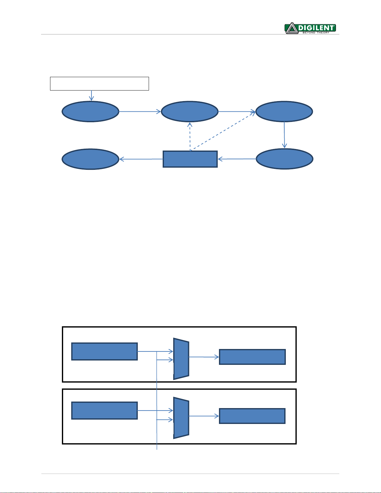
The global trigger bus allows multiple instruments to trigger each other. These trigger source options are:
Page 13

WaveForms™ SDK Reference Manual
Copyright Digilent, Inc. All rights reserved.
Other product and company names mentioned may be trademarks of their respective owners.
Page 13 of 85
Trig Ext
DI/O
ADC
Oscilloscope
Trigger Detector
Control
Analyzer
Trigger Detector
Control
Patterns
Control
Trigger signals bus
Board ON
WaveGen 1
Control
FDwfDeviceTriggerSet(HDWF hdwf, int idxPin, TRIGSRC trigsrc)
Parameters:
- hdwf – Interface handle.
- idxPin – External trigger, I/O pin index.
- trigsrc – Trigger source to set.
The function above is used to configure the trigger I/O pin with a specific TRIGSRC option.
FDwfDeviceTriggerGet(HDWF hdwf, int idxPin, TRIGSRC *ptrigsrc)
Parameters:
- hdwf – Interface handle.
- idxPin - External trigger, I/O pin index.
- ptrigsrc – Variable to receive the current trigger source.
The function above returns the configured trigger setting for a trigger I/O pin. The trigger source can be “none”, an
internal instrument, or an external trigger.
FDwfDeviceTriggerPC(HDWF hdwf)
Parameters:
- hdwf – Interface handle.
The function above generates one pulse on the PC trigger line.
Page 14

WaveForms™ SDK Reference Manual
Copyright Digilent, Inc. All rights reserved.
Other product and company names mentioned may be trademarks of their respective owners.
Page 14 of 85
Start?
Reconfigure?
Trigger?
Start?
Ready
Armed
Running
Done
Instrument configuration or setting
Prefill
Configure
5 Analog In (Oscilloscope)
The Analog In instrument states:
The states are defined in dwf.h DwfState type.
- Ready: Initial state. After FDwfAnalogInConfigure or any FDwfAnalogIn*Set function call goes to this state.
With FDwfAnalogInConfigure, reconfigure goes to Configure state.
- Configure: The needed configurations are performed and auto trigger is reset.
- Prefill: Prefills the buffer with samples needed before trigger.
- Armed: Waits for the trigger.
- Running:
o Single acquisition mode: remains in this state to acquire samples after trigger according trigger
position parameter.
o Scan screen and shift modes: remains in this state until configure or any set function of this
instrument.
o Record mode: the time period according record length parameter.
- Done: Final state.
See the following examples: AnalogIn_Sample/Acquisition/Trigger/Record.py AnalogOutIn.py
5.1 Control
FDwfAnalogInReset(HDWF hdwf)
Parameters:
- hdwf – Interface handle.
The function above resets and configures (by default, having auto configure enabled) all AnalogIn instrument
parameters to default values.
Page 15

WaveForms™ SDK Reference Manual
Copyright Digilent, Inc. All rights reserved.
Other product and company names mentioned may be trademarks of their respective owners.
Page 15 of 85
FDwfAnalogInConfigure(HDWF hdwf, BOOL fReconfigure, BOOL fStart)
Parameters:
- hdwf – Interface handle.
- fReconfigure – Configure the device.
- fStart – Start the acquisition.
The function above is used to configure the instrument and start or stop the acquisition. To reset the Auto trigger
timeout, set fReconfigure to TRUE.
FDwfAnalogInStatus(HDWF hdwf, BOOL fReadData, DwfState *psts)
Parameters:
- hdwf – Interface handle.
- fReadData – TRUE if data should be read.
- psts – Variable to receive the acquisition state.
The function above is used to check the state of the acquisition. To read the data from the device, set fReadData to
TRUE. For single acquisition mode, the data will be read only when the acquisition is finished.
Note: To ensure simultaneity of information and data, all of the following AnalogInStatus** *functions do not
communicate with the device. These functions only return information and data from the last
FDwfAnalogInStatus call.
FDwfAnalogInStatusSamplesLeft(HDWF hdwf, int *pcSamplesLeft)
Parameters:
- hdwf – Interface handle.
- pcSamplesLeft – Variable to receive the remaining samples to acquire.
The function above is used to retrieve the number of samples left in the acquisition.
FDwfAnalogInStatusSamplesValid(HDWF hdwf, int *pcSamplesValid)
Parameters:
- hdwf – Interface handle.
- pcSamplesValid – Variable to receive the number of valid samples.
The function above is used to retrieve the number of valid/acquired data samples.
FDwfAnalogInStatusIndexWrite(HDWF hdwf, int *pidxWrite)
Parameters:
- hdwf – Interface handle.
- pidxWrite – Variable to receive the position of the acquisition.
The function above is used to retrieve the buffer write pointer. This is needed in ScanScreen acquisition mode to
display the scan bar.
Page 16

WaveForms™ SDK Reference Manual
Copyright Digilent, Inc. All rights reserved.
Other product and company names mentioned may be trademarks of their respective owners.
Page 16 of 85
FDwfAnalogInStatusAutoTriggered(HDWF hdwf, BOOL *pfAuto)
Parameters:
- hdwf – Interface handle.
- pfAuto – Returns TRUE if the acquisition was auto triggered.
The function above is used to verify if the acquisition is auto triggered.
FDwfAnalogInStatusData(
HDWF hdwf, int idxChannel, double *rgdVoltData, int cdData)
Parameters:
- hdwf – Interface handle.
- idxChannel – Channel index.
- rgdVoltData – Pointer to allocated buffer to copy the acquisition data.
- cdData – Number of samples to copy.
The function above is used to retrieve the acquired data samples from the specified idxChannel on the AnalogIn
instrument. It copies the data samples to the provided buffer.
FDwfAnalogInStatusNoise(
HDWF hdwf, int idxChannel, double *rgdMin, double *rgdMax, int cdData)
Parameters:
- hdwf – Interface handle.
- idxChannel – Channel index.
- rgdMin – Pointer to allocated buffer to copy the minimum noise data.
- rgdMax – Pointer to allocated buffer to copy the maximum noise data.
- cdData – Number of min/max samples to copy.
The function above is used to retrieve the acquired noise samples from the specified idxChannel on the AnalogIn
instrument. It copies the data samples to the provided buffer.
FDwfAnalogInStatusSample(HDWF hdwf, int idxChannel, double *pdVoltSample)
Parameters:
- hdwf – Interface handle.
- idxChannel – Channel index.
- pdVoltSample – Variable to receive the sample value.
The function above gets the last ADC conversion sample from the specified idxChannel on the AnalogIn
instrument.
Page 17

WaveForms™ SDK Reference Manual
Copyright Digilent, Inc. All rights reserved.
Other product and company names mentioned may be trademarks of their respective owners.
Page 17 of 85
FDwfAnalogInStatusRecord(
HDWF hdwf, int *pcdDataAvailable, int *pcdDataLost, int *pcdDataCorrupt)
Parameters:
- hdwf – Interface handle.
- pcdDataAvailable – Pointer to variable to receive the available number of samples.
- pcdDataLost – Pointer to variable to receive the lost samples after the last check.
- pcdDataCorrupt – Pointer to variable to receive the number of samples that could be corrupt.
The function above is used to retrieve information about the recording process. The data loss occurs when the
device acquisition is faster than the read process to PC. In this case, the device recording buffer is filled and data
samples are overwritten. Corrupt samples indicate that the samples have been overwritten by the acquisition
process during the previous read. In this case, try optimizing the loop process for faster execution or reduce the
acquisition frequency or record length to be less than or equal to the device buffer size (record length <= buffer
size/frequency).
FDwfAnalogInRecordLengthSet(HDWF hdwf, double sLegth)
Parameters:
- hdwf – Interface handle.
- sLegth – Record length to set expressed in seconds.
The function above is used to set the Record length in seconds.
FDwfAnalogInRecordLengthGet(HDWF hdwf, double *psLegth)
Parameters:
- hdwf – Interface handle.
- sLegth – Pointer to variable to receive the record length.
The function above is used to get the current Record length in seconds.
Page 18

WaveForms™ SDK Reference Manual
Copyright Digilent, Inc. All rights reserved.
Other product and company names mentioned may be trademarks of their respective owners.
Page 18 of 85
5.2 Configuration
FDwfAnalogInFrequencyInfo(HDWF hdwf, double *phzMin, double *phzMax)
Parameters:
- hdwf – Interface handle.
- phzMin – Pointer to return the minimum allowed frequency.
- phzMax – Pointer to return the maximum allowed frequency.
The function above is used to retrieve the minimum and maximum (ADC frequency) settable sample frequency.
FDwfAnalogInFrequencySet(HDWF hdwf, double hzFrequency)
Parameters:
- hdwf – Interface handle.
- hzFrequency – Acquisition frequency to set.
The function above is used to set the sample frequency for the instrument.
FDwfAnalogInFrequencyGet(HDWF hdwf, double *phzFrequency)
Parameters:
- hdwf – Interface handle.
- phzFrequency – Variable to receive the acquisition frequency.
The function above is used to read the configured sample frequency. The AnalogIn ADC always runs at maximum
frequency, but the method in which the samples are stored in the buffer can be individually configured for each
channel with FDwfAnalogInChannelFilterSet function.
FDwfAnalogInBitsInfo(HDWF hdwf, int *pnBits)
Parameters:
- hdwf – Interface handle.
- pnBits – Variable to receive the number of ADC bits.
The function above is used to retrieve the number bits used by the AnalogIn ADC.
FDwfAnalogInBufferSizeInfo(HDWF hdwf, int *pnSizeMin, int *pnSizeMax)
Parameters:
- hdwf – Interface handle.
- pnMin – Pointer to return the minimum buffer size.
- pnMax – Pointer to return the maximum buffer size.
The function above returns the minimum and maximum allowable buffer sizes for the instrument.
Page 19

WaveForms™ SDK Reference Manual
Copyright Digilent, Inc. All rights reserved.
Other product and company names mentioned may be trademarks of their respective owners.
Page 19 of 85
FDwfAnalogInBufferSizeSet(HDWF hdwf, int nSize)
Parameters:
- hdwf – Interface handle.
- nSize – Buffer size to set.
The function above is used to adjust the AnalogIn instrument buffer size.
FDwfAnalogInBufferSizeGet(HDWF hdwf, int *pnSize)
Parameters:
- hdwf – Interface handle.
- pnSize – Variable to receive the current buffer size.
The function above returns the used AnalogIn instrument buffer size.
FDwfAnalogInNoiseSizeInfo(HDWF hdwf, int *pnSizeMax)
Parameters:
- hdwf – Interface handle.
- pnMax – Pointer to return the maximum noise buffer size.
The function above returns the maximum buffer size for the instrument.
FDwfAnalogInNoiseSizeGet(HDWF hdwf, int *pnSize)
Parameters:
- hdwf – Interface handle.
- pnSize – Variable to receive the current noise buffer size.
The function above returns the used AnalogIn instrument noise buffer size. This is automatically adjusted
according the sample buffer size. For instance, having maximum buffer size of 8192 and noise buffer size of 512,
setting the sample buffer size to 4096 the noise buffer size will be 256.
FDwfAnalogInAcquisitionModeInfo(HDWF hdwf, int *pfsacqmode)
Parameters:
- hdwf – Interface handle.
- pfsacqmode – Pointer to return the supported acquisition modes.
The function above returns the supported AnalogIn acquisition modes. They are returned (by reference) as a bit
field. This bit field can be parsed using the IsBitSet Macro. Individual bits are defined using the ACQMODE
constants in dwf.h. The acquisition mode selects one of the following modes, ACQMODE:
Page 20

WaveForms™ SDK Reference Manual
Copyright Digilent, Inc. All rights reserved.
Other product and company names mentioned may be trademarks of their respective owners.
Page 20 of 85
ACQMODE Constants
FUNC Constant Capabilities
acqmodeSingle
Perform a single buffer acquisition. This is the default setting.
acqmodeScanShift
Perform a continuous acquisition in FIFO style. The trigger setting is ignored.
The last sample is at the end of buffer. The
FDwfAnalogInStatusSamplesValid function is used to show the
number of the acquired samples, which will grow until reaching the
BufferSize. Then the waveform “picture” is shifted for every new sample.
acqmodeScanScreen
Perform continuous acquisition circularly writing samples into the buffer.
The trigger setting is ignored. The IndexWrite shows the buffer write
position. This is similar to a heart monitor display.
acqmodeRecord
Perform acquisition for length of time set by
FDwfAnalogInRecordLengthSet.
FDwfAnalogInAcquisitionModeSet(HDWF hdwf, ACQMODE acqmode)
Parameters:
- hdwf – Interface handle.
- acqmode – Acquisition mode to set.
The function above is used to set the acquisition mode.
FDwfAnalogInAcquisitionModeGet(HDWF hdwf, ACQMODE *pacqmode)
Parameters:
- hdwf – Interface handle.
- pacqmode – Variable to receive the current acquisition mode.
The function above is used to get retrieve the acquisition mode.
Page 21

WaveForms™ SDK Reference Manual
Copyright Digilent, Inc. All rights reserved.
Other product and company names mentioned may be trademarks of their respective owners.
Page 21 of 85
5.3 Channels
The oscilloscope channel settings are identical across all channels.
FDwfAnalogInChannelCount(HDWF hdwf, int *pcChannel)
Parameters:
- hdwf – Interface handle.
- pcChannel – Variable to receive the number of channels.
The function above is used to read the number of AnalogIn channels of the device.
FDwfAnalogInChannelEnableSet(HDWF hdwf, int idxChannel, BOOL fEnable)
Parameters:
- hdwf – Interface handle.
- idxChannel – Zero based index of channel to enable/disable.
- fEnable – Set TRUE to enable, FALSE to disable.
The function above is used to enable or disable the specified AnalogIn channel.
FDwfAnalogInChannelEnableGet(HDWF hdwf, int idxChannel, BOOL *pfEnable)
Parameters:
- hdwf – Interface handle.
- idxChannel – Index of channel.
- pfEnable – Variable to return enable/disable status of channel.
The function above is used to get the current enable/disable status of the specified AnalogIn channel.
FDwfAnalogInChannelFilterInfo(HDWF hdwf, int *pfsfilter)
Parameters:
- hdwf – Interface handle.
- pfsfilter – Pointer to return the supported acquisition modes.
The function above returns the supported acquisition filters. They are returned (by reference) as a bit field. This bit
field can be parsed using the IsBitSet Macro. Individual bits are defined using the FILTER constants in dwf.h. When
the acquisition frequency (FDwfAnalogInFrequencySet) is less than the ADC frequency (maximum
acquisition frequency), the samples can be stored in one of the following ways using FILTER:
filterDecimate: Store every Nth ADC conversion, where N = ADC frequency /acquisition frequency.
filterAverage: Store the average of N ADC conversions.
filterMinMax: Store interleaved, the minimum and maximum values, of 2xN conversions.
Page 22

WaveForms™ SDK Reference Manual
Copyright Digilent, Inc. All rights reserved.
Other product and company names mentioned may be trademarks of their respective owners.
Page 22 of 85
FDwfAnalogInChannelFilterSet(HDWF hdwf, int idxChannel, FILTER filter)
Parameters:
- hdwf – Interface handle.
- idxChannel – Channel index.
- filter – Acquisition sample filter to set.
The function above is used to set the acquisition filter for each AnalogIn channel. With channel index -1, each
enabled AnalogIn channel filter will be configured to use the same, new option.
FDwfAnalogInChannelFilterGet(HDWF hdwf, int idxChannel, FILTER *pfilter)
Parameters:
- hdwf – Interface handle.
- idxChannel – Channel index.
- pfilter– Variable to receive the current sample filter.
The function above returns the configured acquisition filter.
FDwfAnalogInChannelRangeInfo(
HDWF hdwf, double *pvoltsMin, double *pvoltsMax, double *pnSteps)
Parameters:
- hdwf – Interface handle.
- pvoltsMin – Variable to receive the minimum voltage range.
- pvoltsMax – Variable to receive the maximum voltage range.
- pnSteps – Variable to receive number of steps.
The function above returns the minimum and maximum range, peak to peak values, and the number of adjustable
steps.
FDwfAnalogInChannelRangeSteps(
HDWF hdwf, double rgVoltsStep[32], int *pnSteps)
Parameters:
- hdwf – Interface handle.
- rgVoltsStep – Pointer to buffer to receive the range steps.
- pnSteps – Variable to receive number range steps.
The function above is used to read the range of steps supported by the device. For instance: 1, 2, 5, 10, etc.
Page 23

WaveForms™ SDK Reference Manual
Copyright Digilent, Inc. All rights reserved.
Other product and company names mentioned may be trademarks of their respective owners.
Page 23 of 85
FDwfAnalogInChannelRangeSet(HDWF hdwf, int idxChannel, double voltsRange)
Parameters:
- hdwf – Interface handle.
- idxChannel – Channel index.
- voltsRange – Voltage range to set.
The function above is used to configure the range for each channel. With channel index -1, each enabled Analog In
channel range will be configured to the same, new value.
FDwfAnalogInChannelRangeGet(HDWF hdwf, int idxChannel, double *pvoltsRange)
Parameters:
- hdwf – Interface handle.
- idxChannel – Channel index.
- pvoltsRange – Variable to receive the current voltage range.
The function above returns the real range value for the given channel.
FDwfAnalogInChannelOffsetInfo(
HDWF hdwf, double *pvoltsMin, double *pvoltsMax, double *pnSteps)
Parameters:
- hdwf – Interface handle.
- pvoltsMin – Variable to receive the minimum offset voltage.
- pvoltsMax – Variable to receive the maximum offset voltage.
- pnSteps – Variable to receive the number offset steps.
The function above returns the minimum and maximum offset levels supported, and the number of adjustable
steps.
FDwfAnalogInChannelOffsetSet(HDWF hdwf, int idxChannel, double voltOffset)
Parameters:
- hdwf – Interface handle.
- idxChannel – Channel index.
- voltsRange – Channel offset voltage to set.
The function above is used to configure the offset for each channel. When channel index is specified as -1, each
enabled AnalogIn channel offset will be configured to the same level.
Page 24

WaveForms™ SDK Reference Manual
Copyright Digilent, Inc. All rights reserved.
Other product and company names mentioned may be trademarks of their respective owners.
Page 24 of 85
FDwfAnalogInChannelOffsetGet(HDWF hdwf, int idxChannel, double *pvoltOffset)
Parameters:
- hdwf – Interface handle.
- idxChannel – Channel index.
- pvoltsRange – Variable to receive the offset voltage obtained.
The function above returns for each AnalogIn channel the real offset level.
FDwfAnalogInChannelAttenuationSet(
HDWF hdwf, int idxChannel, double xAttenuation)
Parameters:
- hdwf – Interface handle.
- idxChannel – Channel index.
- voltsRange – Channel offset voltage to set.
The function above is used to configure the attenuation for each channel. When channel index is specified as -1,
each enabled AnalogIn channel attenuation will be configured to the same level. The attenuation does not change
the attenuation on the device, just informs the library about the externally applied attenuation.
FDwfAnalogInChannelAttenuationGet(
HDWF hdwf, int idxChannel, double *pxAttenuation)
Parameters:
- hdwf – Interface handle.
- idxChannel – Channel index.
- pxAttenuation – Variable to receive the attenuation value.
The function above returns for each AnalogIn channel the configured attenuation.
5.4 Trigger
The trigger is used for Single and Record acquisitions. For ScanScreen and ScanShift, the trigger is ignored.
To achieve the classical trigger types:
- None: Set FDwfAnalogInTriggerSourceSet to trigsrcNone.
- Auto: Set FDwfAnalogInTriggerSourceSet to something other than trigsrcNone, such as
trigsrcDetectorAnalogIn and FDwfAnalogInTriggerAutoTimeoutSet to other than zero.
- Normal: Set FDwfAnalogInTriggerSourceSet to something other than trigsrcNone, such as
trigsrcDetectorAnalogIn or FDwfAnalogInTriggerAutoTimeoutSet to zero.
Page 25

WaveForms™ SDK Reference Manual
Copyright Digilent, Inc. All rights reserved.
Other product and company names mentioned may be trademarks of their respective owners.
Page 25 of 85
FDwfAnalogInTriggerSourceInfo(HDWF hdwf, int *pfstrigsrc)
Parameters:
- hdwf – Interface handle.
- pfstrigsrc – Variable to receive the supported trigger sources.
The function above returns the supported trigger source options for the AnalogIn instrument. They are returned
(by reference) as a bit field. This bit field can be parsed using the IsBitSet Macro. Individual bits are defined using
the TRIGSRC constants in dwf.h. For more detail regarding these constants, see the description of
FDwfDeviceTriggerInfo.
FDwfAnalogInTriggerSourceSet(HDWF hdwf, TRIGSRC trigsrc)
Parameters:
- hdwf – Interface handle.
- trigsrc – Trigger source to set.
The function above is used to configure the AnalogIn acquisition trigger source.
FDwfAnalogInTriggerSourceGet(HDWF hdwf, TRIGSRC *ptrigsrc)
Parameters:
- hdwf – Interface handle.
- ptrigsrc – Variable to receive the current trigger source.
The function above returns the configured trigger source. The trigger source can be “none” or an internal
instrument or external trigger. To use the trigger on AnalogIn channels (edge, pulse, etc.), use
trigsrcDetectorAnalogIn.
FDwfAnalogInTriggerPositionInfo(HDWF hdwf, double *psecMin, double *psecMax)
Parameters:
- hdwf – Interface handle.
- psecMin – Variable to receive the minimum trigger position.
- psecMax – Variable to receive the maximum trigger position.
The function above returns the minimum and maximum values of the trigger position in seconds. The horizontal
trigger position is used for Single acquisition mode and it is relative to the buffer middle point.
FDwfAnalogInTriggerPositionSet(HDWF hdwf, double secPosition)
Parameters:
- hdwf – Interface handle.
- secPosition – Trigger position to set.
The function above is used to configure the horizontal trigger position in seconds.
Page 26

WaveForms™ SDK Reference Manual
Copyright Digilent, Inc. All rights reserved.
Other product and company names mentioned may be trademarks of their respective owners.
Page 26 of 85
FDwfAnalogInTriggerPositionGet(HDWF hdwf, double *psecPosition)
Parameters:
- hdwf – Interface handle.
- psecPosition – Variable to receive the current trigger position.
The function above returns the configured trigger position in seconds.
FDwfAnalogInTriggerAutoTimeoutInfo(
HDWF hdwf, double *psecMin, double *psecMax, int *pnSteps)
Parameters:
- hdwf – Interface handle.
- psecMin – Variable to receive the minimum timeout.
- psecMax – Variable to receive the maximum timeout.
- pnSteps – Variable to return the number of steps.
The function above returns the minimum and maximum auto trigger timeout values, and the number of adjustable
steps. The acquisition is auto triggered when the specified time elapses. With zero value the timeout is disabled,
performing “Normal” acquisitions.
FDwfAnalogInTriggerAutoTimeoutSet(HDWF hdwf, double secTimeout)
Parameters:
- hdwf – Interface handle.
- secTimeout – Timeout to set.
The function above is used to configure the auto trigger timeout value in seconds.
FDwfAnalogInTriggerAutoTimeoutGet(HDWF hdwf, double *psecTimeout)
Parameters:
- hdwf – Interface handle.
- psecTimeout – Variable to receive the current timeout.
The function above returns the configured auto trigger timeout value in seconds.
Page 27

WaveForms™ SDK Reference Manual
Copyright Digilent, Inc. All rights reserved.
Other product and company names mentioned may be trademarks of their respective owners.
Page 27 of 85
FDwfAnalogInTriggerHoldOffInfo(
HDWF hdwf, double *psecMin, double *psecMax, double *pnStep)
Parameters:
- hdwf – Interface handle.
- psecMin – Variable to receive the minimum hold off value.
- psecMax – Variable to receive the maximum hold off value.
The function above returns the supported range of the trigger Hold-Off time in Seconds. The trigger hold-off is an
adjustable period of time during which the acquisition will not trigger. This feature is used when you are triggering
on burst waveform shapes, so the oscilloscope triggers only on the first eligible trigger point.
FDwfAnalogInTriggerHoldOffSet(HDWF hdwf, double secHoldOff)
Parameters:
- hdwf – Interface handle.
- secHoldOff – Holdoff to set.
The function above is used to set the trigger hold-off for the AnalongIn instrument in Seconds.
FDwfAnalogInTriggerHoldOffGet(HDWF hdwf, double *psecHoldOff)
Parameters:
- hdwf – Interface handle.
- psecHoldOff – Variable to receive the current holdoff value.
The function above is used to get the current trigger hold-off for the AnalongIn instrument in Seconds.
5.5 Trigger Detector
The following functions configure the trigger detector on analog in channels. To use this, set trigger source with
FDwfAnalogInTriggerSourceSet to trigsrcDetectorAnalogIn.
See the AnalogIn_Trigger.py example.
FDwfAnalogInTriggerTypeInfo(HDWF hdwf, int *pfstrigtype)
Parameters:
- hdwf – Interface handle.
- pfstrigtype – Variable to receive the supported trigger types.
The function above returns the supported trigger type options for the instrument. They are returned (by
reference) as a bit field. This bit field can be parsed using the IsBitSet Macro. Individual bits are defined using the
TRIGTYPE constants in dwf.h. These trigger type options are:
Page 28

WaveForms™ SDK Reference Manual
Copyright Digilent, Inc. All rights reserved.
Other product and company names mentioned may be trademarks of their respective owners.
Page 28 of 85
trigtypeEdge: trigger on rising or falling edge. This is the default setting.
trigtypePulse: trigger on positive or negative; less, timeout, or more pulse lengths.
trigtypeTransition: trigger on rising or falling; less, timeout, or more transition times.
FDwfAnalogInTriggerTypeSet(HDWF hdwf, TRIGTYPE trigtype)
Parameters:
- hdwf – Interface handle.
- trigtype – Trigger type to set.
The function above is used to set the trigger type for the instrument.
FDwfAnalogInTriggerTypeGet(HDWF hdwf, TRIGTYPE *ptrigtype)
Parameters:
- hdwf – Interface handle.
- ptrigtype – Variable to receive the current trigger type.
The function above is used to get the current trigger type for the instrument.
FDwfAnalogInTriggerChannelInfo(HDWF hdwf, int *pidxMin, int *pidxMax)
Parameters:
- hdwf – Interface handle.
- pidxMin – Variable to receive the minimum channel index.
- pidxMax – Variable to receive the maximum channel index.
The function above returns the range of channels that can be triggered on.
FDwfAnalogInTriggerChannelSet(HDWF hdwf, int idxChannel)
Parameters:
- hdwf – Interface handle.
- idxChannel – Trigger channel index to set.
The function above is used to set the trigger channel.
Page 29

WaveForms™ SDK Reference Manual
Copyright Digilent, Inc. All rights reserved.
Other product and company names mentioned may be trademarks of their respective owners.
Page 29 of 85
FDwfAnalogInTriggerChannelGet(HDWF hdwf, int *pidxChannel)
Parameters:
- hdwf – Interface handle.
- pidxChannel – Variable to receive the current trigger channel index.
The function above is used to retrieve the current trigger channel index.
FDwfAnalogInTriggerFilterInfo(HDWF hdwf, int *pfsfilter)
Parameters:
- hdwf – Interface handle.
- pfsFilter – Variable to receive the supported trigger filters.
The function above returns the supported trigger filters. They are returned (by reference) as a bit field. This bit
field can be parsed using the IsBitSet Macro. Individual bits are defined using the FILTER constants in DWF.h.
Select trigger detector sample source, FILTER:
filterDecimate: Looks for trigger in each ADC conversion, can detect glitches.
filterAverage: Looks for trigger only in average of N samples, given by FDwfAnalogInFrequencySet.
FDwfAnalogInTriggerFilterSet(HDWF hdwf, FILTER filter)
Parameters:
- hdwf – Interface handle.
- filter – Trigger filter to set.
The function above is used to set the trigger filter.
FDwfAnalogInTriggerFilterGet(HDWF hdwf, FILTER *pfilter)
Parameters:
- hdwf – Interface handle.
- pfilter – Variable to receive the current trigger filter.
The function above is used to get the trigger filter.
Page 30

WaveForms™ SDK Reference Manual
Copyright Digilent, Inc. All rights reserved.
Other product and company names mentioned may be trademarks of their respective owners.
Page 30 of 85
FDwfAnalogInTriggerConditionInfo(HDWF hdwf, int *pfstrigcond)
Parameters:
- hdwf – Interface handle.
- pfstrigcond – Variable to receive the supported trigger conditions.
The function above returns the supported trigger type options for the instrument. They are returned (by
reference) as a bit field. This bit field can be parsed using the IsBitSet Macro. Individual bits are defined using the
TRIGCOND constants in dwf.h. These trigger condition options are:
trigcondRisingPositive (This is the default setting):
o For edge and transition trigger on rising edge.
o For pulse trigger on positive pulse.
trigcondFallingNegative:
o For edge and transition trigger on falling edge.
o For pulse trigger on negative pulse.
FDwfAnalogInTriggerConditionSet(HDWF hdwf, TRIGCOND trigcond)
Parameters:
- hdwf – Interface handle.
- trigcond – Trigger condition to set.
The function above is used to set the trigger condition for the instrument.
FDwfAnalogInTriggerConditionGet(HDWF hdwf, TRIGCOND *ptrigcond)
Parameters:
- hdwf – Interface handle.
- ptrigcond – Variable to receive the current trigger condition.
The function above is used to set the trigger condition for the instrument.
FDwfAnalogInTriggerLevelInfo(
HDWF hdwf, double *pvoltsMin, double *pvoltsMax, int *pnSteps)
Parameters:
- hdwf – Interface handle.
- pvoltsMin – Variable to receive the minimum voltage level.
- pvoltsMax – Variable to receive the maximum voltage level.
- pnSteps – Variable to receive the number of voltage level steps.
The function above is used to retrieve the range of valid trigger voltage levels for the AnalogIn instrument in Volts.
Page 31

WaveForms™ SDK Reference Manual
Copyright Digilent, Inc. All rights reserved.
Other product and company names mentioned may be trademarks of their respective owners.
Page 31 of 85
FDwfAnalogInTriggerLevelSet(HDWF hdwf, double voltsLevel)
Parameters:
- hdwf – Interface handle.
- voltsLevel – Trigger voltage level to set.
The function above is used to set the trigger voltage level in Volts.
FDwfAnalogInTriggerLevelGet(HDWF hdwf, double *pvoltsLevel)
Parameters:
- hdwf – Interface handle.
- pvoltsLevel – Variable to receive the current trigger voltage level.
The function above is used to get the current trigger voltage level in Volts.
FDwfAnalogInTriggerHysteresisInfo(
HDWF hdwf, double *pvoltsMin, double *pvoltsMax, int *pnSteps)
Parameters:
- hdwf – Interface handle.
- pvoltsMin – Variable to receive the minimum hysteresis level.
- pvoltsMax – Variable to receive the maximum hysteresis level.
- pnSteps – Variable to receive the number of hysteresis level steps.
The function above is used to retrieve the range of valid trigger hysteresis voltage levels for the AnalogIn
instrument in Volts. The trigger detector uses two levels: low level (TriggerLevel - Hysteresis) and high level
(TriggerLevel + Hysteresis). Trigger hysteresis can be used to filter noise for Edge or Pulse trigger. The low and high
levels are used in transition time triggering.
FDwfAnalogInTriggerHysteresisSet(HDWF hdwf, double voltsLevel)
Parameters:
- hdwf – Interface handle.
- voltsLevel – Trigger hysteresis level to set.
The function above is used to set the trigger hysteresis level in Volts.
FDwfAnalogInTriggerHysteresisGet(HDWF hdwf, double *pvoltsHysteresis)
Parameters:
- hdwf – Interface handle.
- pvoltsLevel – Variable to receive the current trigger hysteresis level.
The function above is used to get the current trigger hysteresis level in Volts.
Page 32

WaveForms™ SDK Reference Manual
Copyright Digilent, Inc. All rights reserved.
Other product and company names mentioned may be trademarks of their respective owners.
Page 32 of 85
FDwfAnalogInTriggerLengthConditionInfo(HDWF hdwf, int *pfstriglen)
Parameters:
- hdwf – Interface handle.
- pfsstriglen – Variable to receive the supported trigger length conditions.
The function above returns the supported trigger length condition options for the AnalogIn instrument. They are
returned (by reference) as a bit field. This bit field can be parsed using the IsBitSet Macro. Individual bits are
defined using the TRIGLEN constants in DWF.h. These trigger length condition options are:
triglenLess: Trigger immediately when a shorter pulse or transition time is detected.
triglenTimeout: Trigger immediately as the pulse length or transition time is reached.
triglenMore: Trigger when the length/time is reached and pulse or transition has ended.
FDwfAnalogInTriggerLengthConditionSet(HDWF hdwf, TRIGLEN triglen)
Parameters:
- hdwf – Interface handle.
- triglen – Trigger length condition to set.
The function above is used to set the trigger length condition for the AnalongIn instrument.
FDwfAnalogInTriggerLengthConditionGet(HDWF hdwf, TRIGLEN *ptriglen)
Parameters:
- hdwf – Interface handle.
- ptriglen – Variable to receive the current trigger length condition.
The function above is used to get the current trigger length condition for the AnalongIn instrument.
FDwfAnalogInTriggerLengthInfo(
HDWF hdwf, double *psecMin, double *psecMax, double *pnStep)
Parameters:
- hdwf – Interface handle.
- psecMin – Variable to receive the minimum trigger length.
- psecMax – Variable to receive the maximum trigger length.
The function above returns the supported range of trigger length for the instrument in Seconds. The trigger length
specifies the minimal or maximal pulse length or transition time.
Page 33

WaveForms™ SDK Reference Manual
Copyright Digilent, Inc. All rights reserved.
Other product and company names mentioned may be trademarks of their respective owners.
Page 33 of 85
FDwfAnalogInTriggerLengthSet(HDWF hdwf, double secLength)
Parameters:
- hdwf – Interface handle.
- secLength – Trigger length to set.
The function above is used to set the trigger length in Seconds.
FDwfAnalogInTriggerLengthGet(HDWF hdwf, double *psecLength)
Parameters:
- hdwf – Interface handle.
- secLength – Variable to receive the current trigger length.
The function above is used to get the current trigger length in Seconds.
Page 34
WaveForms™ SDK Reference Manual
Copyright Digilent, Inc. All rights reserved.
Other product and company names mentioned may be trademarks of their respective owners.
Page 34 of 85
Trigger?
Start?
Ready
Armed
Wait
Running
Repeat
Done
Instrument configuration or setting
Analog Out 2
Analog Out 1
States
Generator
Master
States
Generator
Master
...
...
...
6 Analog Out (Arbitrary Waveform Generator)
The Analog Out instrument states:
The states are defined in dwf.h DwfState type.
- Ready: Initial state. After FDwfAnalogOutConfigure or any FDwfAnalogOut*Set function call goes to this state.
With digital out, configure start command goes to Armed state.
- Armed: It waits for trigger.
- Wait: Remains in this state for the time period specified by FDwfAnalogOutWaitSet function.
- Running: Remains in this state for the time period specified by FDwfAnalogOutRunSet function.
- Repeat: Goes to Armed or Wait state according to the FDwfAnalogOutRepeatTriggerSet setting for the
number of times specified by FDwfAnalogOutRepeatSet.
- Done: Final state.
The analog out channels can run independently or synchronized using the master parameter. The states are
defined by trigger, wait, run, and repeat options. It is enough to start with FDwfAnalogOutConfigure (the master
channel) the slave channels will also start.
See the following examples: AnalogOut_Sine/Sweep/Custom/Sync.py AnalogOutIn.py
Page 35

WaveForms™ SDK Reference Manual
Copyright Digilent, Inc. All rights reserved.
Other product and company names mentioned may be trademarks of their respective owners.
Page 35 of 85
Page 36

WaveForms™ SDK Reference Manual
Copyright Digilent, Inc. All rights reserved.
Other product and company names mentioned may be trademarks of their respective owners.
Page 36 of 85
6.1 Control
FDwfAnalogOutReset(HDWF hdwf, int idxChannel)
Parameters:
- hdwf – Interface handle.
- idxChannel – Channel index.
The function above resets and configures (by default, having auto configure enabled) all AnalogOut instrument
parameters to default values for the specified channel. To reset instrument parameters across all channels, set
idxChannel to -1.
FDwfAnalogOutConfigure(HDWF hdwf, int idxChannel, BOOL fStart)
Parameters:
- hdwf – Interface handle.
- idxChannel – Channel index.
- fStart – Start the instrument. To stop, set to FALSE.
The function above is used to start or stop the instrument. With channel index -1, each enabled Analog Out
channel will be configured.
FDwfAnalogOutStatus(HDWF hdwf, int idxChannel, DwfState *psts)
Parameters:
- hdwf – Open interface handle on a device.
- idxChannel – Channel index.
- psts – Pointer to variable to return the state.
The function above is used to check the state of the instrument.
FDwfAnalogOutNodePlayStatus(HDWF hdwf, int idxChannel, AnalogOutNode node,
int *cdDataFree, int *cdDataLost, int *cdDataCorrupted)
Parameters:
- hdwf – Open interface handle on a device.
- idxChannel – Channel index.
- node – Node index.
- cdDataFree – Pointer to variable to return the available free buffer space, the number of new samples that can
be sent.
- cdDataLost – Pointer to variable to return the number of lost samples.
- cdDataCorrupted – Pointer to variable to return the number of samples that could be corrupted.
The function above is used to retrieve information about the play process. The data lost occurs when the device
generator is faster than the sample send process from the PC. In this case, the device buffer gets emptied and
generated samples are repeated. Corrupt samples are a warning that the buffer might have been emptied while
samples were sent to the device. In this case, try optimizing the loop for faster execution; or reduce the frequency
or run time to be less or equal to the device buffer size (run time <= buffer size/frequency).
Page 37

WaveForms™ SDK Reference Manual
Copyright Digilent, Inc. All rights reserved.
Other product and company names mentioned may be trademarks of their respective owners.
Page 37 of 85
FDwfAnalogOutNodePlayData(
HDWF hdwf, int idxChannel, AnalogOutNode node, double *rgdData, int cdData)
Parameters:
- hdwf – Open interface handle on a device.
- idxChannel – Channel index.
- node – Node index.
- rgdData – Pointer to samples array to be sent to the device.
- cdData – Number of samples to send.
The function above is used to sending new data samples for play mode. Before starting the Analog Out
instrument, prefill the device buffer with the first set of samples using the AnalogOutNodeDataSet function. In the
loop of sending the following samples, first call AnalogOutStatus to read the information from the device, then
AnalogOutPlayStatus to find out how many new samples can be sent, then send the samples with
AnalogOutPlayData.
6.2 Configuration
FDwfAnalogOutCount(HDWF hdwf, int *pcChannel)
Parameters:
- hdwf – Open interface handle on a device.
- pcChannel – Pointer to variable to receive the number of channels in the instrument.
The function above returns the number of Analog Out channels by the device specified by hdwf.
FDwfAnalogOutNodeInfo(HDWF hdwf, int idxChannel, int *pfsnode)
Parameters:
- hdwf – Open interface handle on a device.
- idxChannel – Channel index.
- pfsnode – Variable to receive the supported nodes.
The function above returns the supported AnalogOut nodes of the AnalogOut channel. They are returned (by
reference) as a bit field. This bit field can be parsed using the IsBitSet Macro. Individual bits are defined using the
AnalogOutNode constants in dwf.h. These node types are:
AnalogOutNodeCarrier
AnalogOutNodeFM
AnalogOutNodeAM
Page 38

WaveForms™ SDK Reference Manual
Copyright Digilent, Inc. All rights reserved.
Other product and company names mentioned may be trademarks of their respective owners.
Page 38 of 85
FDwfAnalogOutNodeEnableSet(
HDWF hdwf, int idxChannel, AnalogOutNode node, BOOL fEnable)
Parameters:
- hdwf – Open interface handle on a device.
- idxChannel – Channel index.
- node – Node index.
- fEnable – TRUE to enable, FALSE to disable.
The function above enables or disables the channel node specified by idxChannel and node. The Carrier node
enables or disables the channel and AM/FM the modulation. With channel index -1, each Analog Out channel
enable will be configured to use the same, new option.
FDwfAnalogOutNodeEnableGet(
HDWF hdwf, int idxChannel, AnalogOutNode node, BOOL *pfEnable)
Parameters:
- hdwf – Open interface handle on a device.
- idxChannel – Channel index.
- node – Node index.
- pfEnable – Pointer to variable to receive enabled state.
The function above is used to verify if a specific channel and node is enabled or disabled.
Page 39

WaveForms™ SDK Reference Manual
Copyright Digilent, Inc. All rights reserved.
Other product and company names mentioned may be trademarks of their respective owners.
Page 39 of 85
FUNC Constants
FUNC Constant Capabilities
funcDC
Generate DC value set as offset.
FuncSine
Generate sine waveform.
funcSquare
Generate square waveform.
funcTriangle
Generate triangle waveform.
funcRampUp
Generate a waveform with a ramp-up voltage at the beginning.
funcRampDown
Generate a waveform with a ramp-down voltage at the end.
funcNoise
Generate noise waveform from random samples.
funcCustom
Generate waveform from custom repeated data.
funcPlay
Generate waveform from custom data in stream play style.
FDwfAnalogOutNodeFunctionInfo(
HDWF hdwf, int idxChannel, AnalogOutNode node, int *pfsfunc)
Parameters:
- hdwf – Open interface handle on a device.
- idxChannel – Channel index.
- node – Node index.
- pfsfunc – Variable to receive the supported generator function options.
The function above returns the supported generator function options. They are returned (by reference) as a bit
field. This bit field can be parsed using the IsBitSet Macro. Individual bits are defined using the FUNC constants in
dwf.h. These are:
FDwfAnalogOutNodeFunctionSet(
HDWF hdwf, int idxChannel, AnalogOutNode node, FUNC func)
Parameters:
- hdwf – Open interface handle on a device.
- idxChannel – Channel index.
- node – Node index.
- func – Generator function option to set.
The function above is used to set the generator output function for the specified instrument channel. With channel
index -1, each enabled Analog Out channel function will be configured to use the same, new option.
Page 40

WaveForms™ SDK Reference Manual
Copyright Digilent, Inc. All rights reserved.
Other product and company names mentioned may be trademarks of their respective owners.
Page 40 of 85
FDwfAnalogOutNodeFunctionGet(
HDWF hdwf, int idxChannel, AnalogOutNode node, FUNC *pfunc)
Parameters:
- hdwf – Open interface handle on a device.
- idxChannel – Channel index.
- node – Node index.
- ptrigsrc – Pointer to variable to receive the generator function option.
The function above is used to retrieve the current generator function option for the specified instrument channel.
FDwfAnalogOutNodeFrequencyInfo(HDWF hdwf, int idxChannel, AnalogOutNode node,
double *phzMin, double *phzMax)
Parameters:
- hdwf – Open interface handle on a device.
- idxChannel – Zero based channel index.
- node – Zero based node index.
- phzMin – Variable to receive the supported minimum frequency.
- phzMax – Variable to receive the supported maximum frequency.
The function above is used to return the supported frequency range for the instrument. The maximum value
shows the DAC frequency. The frequency of the generated waveform: repetition frequency for standard types and
custom data; DAC update for noise type; sample rate for play type.
FDwfAnalogOutNodeFrequencySet(
HDWF hdwf, int idxChannel, AnalogOutNode node, double hzFrequency)
Parameters:
- hdwf – Open interface handle on a device.
- idxChannel – Channel index.
- node – Node index.
- hzFrequency – Frequency value to set expressed in Hz.
The function above is used to set the frequency. With channel index -1, each enabled Analog Out channel
frequency will be configured to use the same, new option.
FDwfAnalogOutNodeFrequencyGet(
HDWF hdwf, int idxChannel, AnalogOutNode node, double *phzFrequency)
Parameters:
- hdwf – Open interface handle on a device.
- idxChannel – Channel index.
- node – Node index.
- hzFrequency – Pointer to variable to receive frequency value in Hz.
The function above is used to get the currently set frequency for the specified channel-node on the instrument.
Page 41

WaveForms™ SDK Reference Manual
Copyright Digilent, Inc. All rights reserved.
Other product and company names mentioned may be trademarks of their respective owners.
Page 41 of 85
FDwfAnalogOutNodeAmplitudeInfo(
HDWF hdwf, int idxChannel, AnalogOutNode node, double *pvMin, double *pvMax)
Parameters:
- hdwf – Open interface handle on a device.
- idxChannel – Channel index.
- node – Node index.
- pvMin – Minimum amplitude level or modulation index.
- pvMax – Maximal amplitude level or modulation index.
The function above is used to retrieve the amplitude range for the specified channel-node on the instrument. The
amplitude is expressed in Volt units for carrier and in percentage units (modulation index) for AM/FM.
FDwfAnalogOutNodeAmplitudeSet(
HDWF hdwf, int idxChannel, AnalogOutNode node, double vAmplitude)
Parameters:
- hdwf – Open interface handle on a device.
- idxChannel – Channel index.
- node – Node index.
- vAmplitude – Amplitude of channel in Volts or modulation index in percentage.
The function above is used to set the amplitude or modulation index for the specified channel-node on the
instrument. With channel index -1, each enabled Analog Out channel amplitude (or modulation index) will be
configured to use the same, new option.
FDwfAnalogOutNodeAmplitudeGet(
HDWF hdwf, int idxChannel, AnalogOutNode node, double *pvAmplitude)
Parameters:
- hdwf – Open interface handle on a device.
- idxChannel – Channel index.
- node – Node index.
- pvAmplitude – Pointer to variable to receive amplitude value in Volts or modulation index in percentage.
The function above is used to get the currently set amplitude or modulation index for the specified channel-node
on the instrument.
Page 42

WaveForms™ SDK Reference Manual
Copyright Digilent, Inc. All rights reserved.
Other product and company names mentioned may be trademarks of their respective owners.
Page 42 of 85
FDwfAnalogOutNodeOffsetInfo(
HDWF hdwf, int idxChannel, AnalogOutNode node, double *pvMin, double *pvMax)
Parameters:
- hdwf – Open interface handle on a device.
- idxChannel – Channel index.
- node – Node index.
- pvMin – Minimum offset voltage or modulation offset percentage.
- pvMax – Maximum offset voltage or modulation offset percentage.
The function above is used to retrieve available the offset range. For carrier node in units of volts, and in
percentage units for AM/FM nodes.
FDwfAnalogOutNodeOffsetSet(
HDWF hdwf, int idxChannel, AnalogOutNode node, double vOffset)
Parameters:
- hdwf – Open interface handle on a device.
- idxChannel – Channel index.
- node – Node index.
- vOffset – Value to set voltage offset in Volts or modulation offset percentage.
The function above is used to set the offset value for the specified channel-node on the instrument. With channel
index -1, each enabled Analog Out channel offset will be configured to use the same, new option.
FDwfAnalogOutNodeOffsetGet(HDWF hdwf, int idxChannel, AnalogOutNode node,
double *pvOffset)
Parameters:
- hdwf – Open interface handle on a device.
- idxChannel – Channel index.
- node – Node index.
- pvOffset – Pointer to variable to receive offset value in Volts or modulation offset percentage.
The function above is used to get the current offset value for the specified channel-node on the instrument.
FDwfAnalogOutNodeSymmetryInfo(HDWF hdwf, int idxChannel, AnalogOutNode node,
double *ppercentageMin, double *ppercentageMax)
Parameters:
- hdwf – Open interface handle on a device.
- idxChannel – Channel index.
- node – Node index.
- ppercentageMin – Minimum value of Symmetry percentage.
- ppercentageMax – Maximum value of Symmetry percentage.
The function above is used to obtain the symmetry (or duty cycle) range (0..100). This symmetry is supported for
standard signal types. It the pulse duration divided by the pulse period.
Page 43

WaveForms™ SDK Reference Manual
Copyright Digilent, Inc. All rights reserved.
Other product and company names mentioned may be trademarks of their respective owners.
Page 43 of 85
FDwfAnalogOutNodeSymmetrySet(HDWF hdwf, int idxChannel, AnalogOutNode node,
AnalogOutNode node, double percentageSymmetry)
Parameters:
- hdwf – Open interface handle on a device.
- idxChannel – Channel index.
- node – Node index.
- percentageSymmetry –Value of percentage of Symmetry (duty cycle).
The function above is used to set the symmetry (or duty cycle) for the specified channel-node on the instrument.
With channel index -1, each enabled Analog Out channel symmetry will be configured to use the same, new
option.
FDwfAnalogOutNodeSymmetryGet(
HDWF hdwf, int idxChannel, AnalogOutNode node, double *ppercentageSymmetry)
Parameters:
- hdwf – Open interface handle on a device.
- idxChannel – Channel index.
- node – Node index.
- ppercentageSymmetry –– Pointer to variable to receive value of Symmetry (duty cycle).
The function above is used to get the currently set symmetry (or duty cycle) for the specified channel-node of the
instrument.
FDwfAnalogOutNodePhaseInfo(HDWF hdwf, int idxChannel, AnalogOutNode node,
double *pdegreeMin, double *pdegreeMax)
Parameters:
- hdwf – Open interface handle on a device.
- idxChannel – Channel index.
- node – Node index.
- pdegreeMin – Minimum value of Phase (in degrees).
- pdegreeMax – Maximum value of Phase (in degrees).
The function above is used to retrieve the phase range (in degrees 0...360) for the specified channel-node of the
instrument.
FDwfAnalogOutNodePhaseSet(
HDWF hdwf, int idxChannel, AnalogOutNode node, double degreePhase)
Parameters:
- hdwf – Open interface handle on a device.
- idxChannel – Channel index.
- node – Node index.
- degreePhase – Value of Phase in degrees.
The function above is used to set the phase for the specified channel-node on the instrument. With channel index 1, each enabled Analog Out channel phase will be configured to use the same, new option.
Page 44

WaveForms™ SDK Reference Manual
Copyright Digilent, Inc. All rights reserved.
Other product and company names mentioned may be trademarks of their respective owners.
Page 44 of 85
FDwfAnalogOutNodePhaseGet(HDWF hdwf, int idxChannel, AnalogOutNode node,
double *pdegreePhase)
Parameters:
- hdwf – Open interface handle on a device.
- idxChannel – Channel index.
- node – Node index.
- pdegreePhase – Pointer to variable to receive Phase value (in degrees).
The function above is used to get the current phase for the specified channel-node on the instrument.
FDwfAnalogOutNodeDataInfo(HDWF hdwf, int idxChannel, AnalogOutNode node,
int *pnSamplesMin, double *pnSamplesMax)
Parameters:
- hdwf – Open interface handle on a device.
- idxChannel – Channel index.
- node – Node index.
- pnSamplesMin - Minimum number of samples available for custom data.
- pnSamplesMax – Maximum number of samples available for custom data.
The function above is used to retrieve the minimum and maximum number of samples allowed for custom data
generation.
FDwfAnalogOutNodeDataSet(
HDWF hdwf, int idxChannel, AnalogOutNode node, double *rgdData, int cdData)
Parameters:
- hdwf – Open interface handle on a device.
- idxChannel – Channel index.
- node – Node index.
- rgbData – Buffer of samples to set.
- cData – Number of samples to set in rgbData.
The function above is used to set the custom data or to prefill the buffer with play samples. The samples are
double precision floating point values (rgdData) normalized to ±1.
With the custom function option, the data samples (cdData) will be interpolated to the device buffer size. The
output value will be Offset + Sample*Amplitude, for instance:
- 0 value sample will output: Offset.
- +1 value sample will output: Offset + Amplitude.
- -1 value sample will output: Offset – Amplitude.
Page 45

WaveForms™ SDK Reference Manual
Copyright Digilent, Inc. All rights reserved.
Other product and company names mentioned may be trademarks of their respective owners.
Page 45 of 85
FDwfAnalogOutLimitationInfo(
HDWF hdwf, int idxChannel, double *pvMin, double *pvMax)
Parameters:
- hdwf – Open interface handle on a device.
- idxChannel – Channel index.
- pvMin – Minimum limitation value.
- pvMax – Maximum offset voltage or modulation offset percentage.
The function above is used to retrieve available the limitation range. This option is supported on Electronics
Explorer Analog Out Channel 3 and 4, Positive and Negative Power supplies, to set current or voltage limitation.
FDwfAnalogOutLimitationSet(HDWF hdwf, int idxChannel, double limit)
Parameters:
- hdwf – Open interface handle on a device.
- idxChannel – Channel index.
- limit – Value to set voltage offset in Volts or modulation offset percentage.
The function above is used to set the limitation value for the specified channel on the instrument. With channel
index -1, each enabled Analog Out channel limitation will be configured to use the same, new option.
FDwfAnalogOutLimitationGet(HDWF hdwf, int idxChannel, double *plimit)
Parameters:
- hdwf – Open interface handle on a device.
- idxChannel – Channel index.
- limit – Pointer to variable to receive offset value in Volts or modulation offset percentage.
The function above is used to get the current limitation value for the specified channel on the instrument.
FDwfAnalogOutModeSet(HDWF hdwf, int idxChannel, DwfAnalogOutMode mode)
Parameters:
- hdwf – Open interface handle on a device.
- idxChannel – Channel index.
- mode – Generator mode option to set.
The function above is used to set the generator output mode for the specified instrument channel. With channel
index -1, each enabled Analog Out channel mode will be configured to use the same, new option. This option is
supported on Electronics Explorer Analog Out Channel 3 and 4, Positive and Negative Power supplies, to set
current or voltage waveform generator mode.
The DwfAnalogOutMode options are:
DwfAnalogOutModeVoltage
DwfAnalogOutModeCurren
Page 46

WaveForms™ SDK Reference Manual
Copyright Digilent, Inc. All rights reserved.
Other product and company names mentioned may be trademarks of their respective owners.
Page 46 of 85
Idle Constants
Idle Constant Capabilities
DwfAnalogOutIdleDisable
Supported on Electronics Explorer:
Channel 1&2 0V ouput
Channel 3&4. having 1 kΩ resistor to GND and diode
DwfAnalogOutIdleOffset
The idle output is the configured Offset level.
DwfAnalogOutIdleInitial
The idle output voltage level has the initial waveform value of the
current configuration. This depends on the selected signal type,
Offset, Amplitude and Amplitude Modulator configuration.
FDwfAnalogOutModeGet(HDWF hdwf, int idxChannel, DwfAnalogOutMode *pmode)
Parameters:
- hdwf – Open interface handle on a device.
- idxChannel – Channel index.
- mode – Pointer to variable to receive the generator mode option.
The function above is used to retrieve the current generator mode option for the specified instrument channel.
FDwfAnalogOutIdleInfo(HDWF hdwf, int idxChannel, int *pfsidle)
Parameters:
- hdwf – Open interface handle on a device.
- idxChannel – Channel index.
- pfsidlec – Variable to receive the supported generator idle options.
The function above returns the supported generator idle output options. They are returned (by reference) as a bit
field. This bit field can be parsed using the IsBitSet Macro. Individual bits are defined using the DwfAnalogOutIdle
constants in dwf.h. These are:
FDwfAnalogOutIdleSet(HDWF hdwf, int idxChannel, DwfAnalogOutIdle idle)
Parameters:
- hdwf – Open interface handle on a device.
- idxChannel – Channel index.
- idle – Generator function option to set.
The function above is used to set the generator idle output for the specified instrument channel. The idle output
selects the output while not running, Ready, Stopped, Done or Wait states.
FDwfAnalogOutIdleGet(HDWF hdwf, int idxChannel, DwfAnalogOutIdle *pidle)
Parameters:
- hdwf – Open interface handle on a device.
- idxChannel – Channel index.
- pidle – Pointer to variable to receive the generator function option.
The function above is used to retrieve the generator idle output option for the specified instrument channel.
Page 47

WaveForms™ SDK Reference Manual
Copyright Digilent, Inc. All rights reserved.
Other product and company names mentioned may be trademarks of their respective owners.
Page 47 of 85
6.3 States
FDwfAnalogOutTriggerSourceInfo(HDWF hdwf, int idxChannel, int *pfstrigsrc)
Parameters:
- hdwf – Open interface handle on a device.
- idxChannel – Channel index.
- pfstrigsrc – Variable to receive the supported trigger sources.
The function above returns the supported trigger source options for the instrument. See the description of
FDwfDeviceTriggerInfo.
FDwfAnalogOutTriggerSourceSet(HDWF hdwf, int idxChannel, TRIGSRC trigsrc)
Parameters:
- hdwf – Open interface handle on a device.
- idxChannel – Channel index.
- trigsrc – Trigger source to set.
The function above is used to set the trigger source for the channel on instrument.
FDwfAnalogOutTriggerSourceGet(HDWF hdwf, int idxChannel, TRIGSRC *ptrigsrc)
Parameters:
- hdwf – Open interface handle on a device.
- idxChannel – Channel index.
- ptrigsrc – Pointer to variable to receive the trigger source.
The function above is used to get the current trigger source setting for the channel on instrument.
FDwfAnalogOutRunInfo(HDWF hdwf, int idxChannel, double *psecMin, double
*psecMax)
Parameters:
- hdwf – Open interface handle on a device.
- idxChannel – Channel index.
- psecMin – Variable to receive the supported minimum run length.
- psecMax – Variable to receive the supported maximum run length.
The function above is used to return the supported run length range for the instrument in Seconds. Zero values
represent an infinite (or continuous) run. Default value is zero.
Page 48

WaveForms™ SDK Reference Manual
Copyright Digilent, Inc. All rights reserved.
Other product and company names mentioned may be trademarks of their respective owners.
Page 48 of 85
FDwfAnalogOutRunSet(HDWF hdwf, int idxChannel, double secRun)
Parameters:
- hdwf – Open interface handle on a device.
- idxChannel – Channel index.
- secRun – Run length to set expressed in seconds.
The function above is used to set the run length for the instrument in Seconds.
FDwfAnalogOutRunGet(HDWF hdwf, int idxChannel, double *psecRun)
Parameters:
- hdwf – Open interface handle on a device.
- idxChannel – Channel index.
- psecRun – Pointer to variable to receive the run length.
The function above is used to read the configured run length for the instrument in Seconds.
FDwfAnalogOutRunStatus(HDWF hdwf, int idxChannel, double *psecRun)
Parameters:
- hdwf – Open interface handle on a device.
- idxChannel – Channel index.
- psecRun – Pointer to variable to receive the remaining run length.
The function above is used to read the remaining run length. It returns data from the last FDwfAnalogOutStatus
call.
FDwfAnalogOutWaitInfo(HDWF hdwf, int idxChannel, double *psecMin, double
*psecMax)
Parameters:
- hdwf – Open interface handle on a device.
- idxChannel – Channel index.
- psecMin – Variable to receive the supported minimum wait length.
- psecMax – Variable to receive the supported maximum wait length.
The function above is used to return the supported wait length range in Seconds. The wait length is how long the
instrument waits after being triggered to generate the signal. Default value is zero.
FDwfAnalogOutWaitSet(HDWF hdwf, int idxChannel, double secWait)
Parameters:
- hdwf – Open interface handle on a device.
- idxChannel – Channel index.
- secWait – Wait length to set expressed in seconds.
The function above is used to set the wait length for the channel on instrument.
Page 49

WaveForms™ SDK Reference Manual
Copyright Digilent, Inc. All rights reserved.
Other product and company names mentioned may be trademarks of their respective owners.
Page 49 of 85
FDwfAnalogOutWaitGet(HDWF hdwf, int idxChannel, double *psecWait)
Parameters:
- hdwf – Open interface handle on a device.
- idxChannel – Channel index.
- psecWait – Pointer to variable to receive the wait length.
The function above is used to get the current wait length for the channel on instrument.
FDwfAnalogOutRepeatInfo(HDWF hdwf, int idxChannel, int *pnMin, int *pnMax)
Parameters:
- hdwf – Open interface handle on a device.
- idxChannel – Channel index.
- pnMin – Variable to receive the supported minimum repeat count.
- pnMax – Variable to receive the supported maximum repeat count.
The function above is used to return the supported repeat count range. This is how many times the generated
signal will be repeated upon. Zero value represents infinite repeat. Default value is one.
FDwfAnalogOutRepeatSet(HDWF hdwf, int idxChannel, int cRepeat)
Parameters:
- hdwf – Open interface handle on a device.
- idxChannel – Channel index.
- cRepeat – Repeat count to set.
The function above is used to set the repeat count.
FDwfAnalogOutRepeatGet(HDWF hdwf, int idxChannel, int *pcRepeat)
Parameters:
- hdwf – Open interface handle on a device.
- idxChannel – Channel index.
- pcRepeat – Pointer to variable to receive the repeat count.
The function above is used to read the current repeat count.
FDwfAnalogOutRepeatStatus(HDWF hdwf, int idxChannel, int *pcRepeat)
Parameters:
- hdwf – Open interface handle on a device.
- idxChannel – Channel index.
- pcRepeat – Pointer to variable to receive the remaining repeat counts.
The function above is used to read the remaining repeat counts. It only returns information from the last
FDwfAnalogOutStatus function call, it does not read from the device.
Page 50

WaveForms™ SDK Reference Manual
Copyright Digilent, Inc. All rights reserved.
Other product and company names mentioned may be trademarks of their respective owners.
Page 50 of 85
FDwfAnalogOutRepeatTriggerSet(HDWF hdwf, int idxChannel, BOOL fRepeatTrigger)
Parameters:
- hdwf – Open interface handle on a device.
- idxChannel – Channel index.
- fRepeatTrigger – Boolean used to specify if the trigger should be included in a repeat cycle.
The function above is used to set the repeat trigger option. To include the trigger in wait-run repeat cycles, set
fRepeatTrigger to TRUE. It is disabled by default.
FDwfAnalogOutRepeatTriggerGet(
HDWF hdwf, int idxChannel, BOOL *pfRepeatTrigger)
Parameters:
- hdwf – Open interface handle on a device.
- idxChannel – Channel index.
- pfRepeatTrigger – Pointer to variable to receive the repeat trigger option.
The function above is used to verify if the trigger has been included in wait-run repeat cycles.
FDwfAnalogOutMasterSet(HDWF hdwf, int idxChannel, int idxMaster)
Parameters:
- hdwf – Open interface handle on a device.
- idxChannel – Channel index.
- idxMaster – Node index.
The function above sets the state machine master of the channel generator. With channel index -1, each enabled
Analog Out channel will be configured to use the same, new option.
FDwfAnalogOutMasterGet(HDWF hdwf, int idxChannel, int *pidxMaster)
Parameters:
- hdwf – Open interface handle on a device.
- idxChannel – Channel index.
- pidxMaster – Pointer to variable to receive parameter.
The function above is used to verify the parameter.
Page 51

WaveForms™ SDK Reference Manual
Copyright Digilent, Inc. All rights reserved.
Other product and company names mentioned may be trademarks of their respective owners.
Page 51 of 85
7 Analog I/O
The AnalogIO functions are used to control the power supplies, reference voltage supplies, voltmeters, ammeters,
thermometers, and any other sensors on the device. These are organized into channels which contain a number of
nodes. For instance, a power supply channel might have three nodes: an enable setting, a voltage level
setting/reading, and current limitation setting/reading.
See the AnalogIO.py example.
FDwfAnalogIOReset(HDWF hdwf)
Parameters:
- hdwf – Open interface handle on a device.
The function above resets and configures (by default, having auto configure enabled) all AnalogIO instrument
parameters to default values.
FDwfAnalogIOConfigure(HDWF hdwf)
Parameters:
- hdwf – Open interface handle on a device.
The function above is used to configure the instrument.
FDwfAnalogIOStatus(HDWF hdwf)
Parameters:
- hdwf – Open interface handle on a device.
The function above reads the status of the device and stores it internally. The following status functions will return
the information that was read from the device when the function above was called.
FDwfAnalogIOEnableInfo(HDWF hdwf, BOOL *pfSet, BOOL *pfStatus)
Parameters:
- hdwf – Open interface handle on a device.
- pfSet – Returns true when the master enable setting is supported.
- pfStatus – Return true when the status of the master enable can be read.
The function above is used to verify if Master Enable Setting and/or Master Enable Status are supported for the
AnalogIO instrument. The Master Enable setting is essentially a software switch that “enables” or “turns on” the
AnalogIO channels. If supported, the status of this Master Enable switch (Enabled/Disabled) can be queried by
calling FDwfAnalogIOEnableStatus.
Page 52

WaveForms™ SDK Reference Manual
Copyright Digilent, Inc. All rights reserved.
Other product and company names mentioned may be trademarks of their respective owners.
Page 52 of 85
FDwfAnalogIOEnableSet(HDWF hdwf, BOOL fMasterEnable)
Parameters:
- hdwf – Open interface handle on a device.
- fMasterEnable – Set TRUE to enable the master switch; FALSE to disable the master switch.
The function above is used to set the master enable switch.
FDwfAnalogIOEnableGet(HDWF hdwf, BOOL *pfMasterEnable)
Parameters:
- hdwf – Open interface handle on a device.
- pfMasterEnable – Pointer to variable to return the enabled configuration.
The function above returns the current state of the master enable switch. This is not obtained from the device.
FDwfAnalogIOEnableStatus(HDWF hdwf, BOOL *pfMasterEnable)
Parameters:
- hdwf – Open interface handle on a device.
- pfMasterEnabled – Pointer to variable to return the active status.
The function above returns the master enable status (if the device supports it). This can be a switch on the board
or an overcurrent protection circuit state.
FDwfAnalogIOChannelCount(HDWF hdwf, int *pnChannel)
Parameters:
- hdwf – Open interface handle on a device.
- pnChannel – Pointer to variable to return the number of channels.
The function above returns the number of AnalogIO channels available on the device.
FDwfAnalogIOChannelName(
HDWF hdwf, int idxChannel, char szName[32], char szLabel[16])
Parameters:
- hdwf – Open interface handle on a device.
- idxChannel – Channel index.
- szName – Pointer to character array to return the user name.
- szLabel – Pointer to character array to return the label.
The function above returns the name (long text) and label (short text, printed on the device) for a channel.
Page 53

WaveForms™ SDK Reference Manual
Copyright Digilent, Inc. All rights reserved.
Other product and company names mentioned may be trademarks of their respective owners.
Page 53 of 85
ANALOGIO Modes
ANALOGIO Mode Functions
analogioEnable
Enable I/O node; used to enable a power supply, reference voltage, etc.
analogioVoltage
Voltage I/O node; used to input/output voltage levels.
analogioCurrent
Current I/O node; used to input/output current levels.
analogioTemperature
Temperature I/O node; used to retrieve read values from a temperature sensor.
FDwfAnalogIOChannelInfo(HDWF hdwf, int idxChannel, int *pnNodes)
Parameters:
- hdwf – Open interface handle on a device.
- idxChannel – Channel index.
- pnNodes – Pointer to variable to return the number of node .
The function above returns the number of nodes associated with the specified channel.
FDwfAnalogIOChannelNodeName(
HDWF hdwf, int idxChannel, char szNodeName[32], char szUnits[16])
Parameters:
- hdwf – Open interface handle on a device.
- idxChannel – Channel index.
- szNodeName – Pointer to character array to return the node name.
- szUnits – Pointer to character array to return the value units.
The function above returns the node name (“Voltage”, “Current”…) and units (“V”, “A”) for an Analog I/O node.
FDwfAnalogIOChannelNodeInfo(
HDWF hdwf, int idxChannel, int idxNode, ANALOGIO *panalogio)
Parameters:
- hdwf – Open interface handle on a device.
- idxChannel – Channel index.
- idxNode – Node index.
- panalogio – Pointer to variable to return the node type.
The function above returns the supported channel nodes. They are returned (by reference) as a bit field. This bit
field can be parsed using the IsBitSet Macro. Individual bits are defined using the ANALOGIO constants in dwf.h.
The acquisition mode selects one of the following modes, ANALOGIO:
Page 54

WaveForms™ SDK Reference Manual
Copyright Digilent, Inc. All rights reserved.
Other product and company names mentioned may be trademarks of their respective owners.
Page 54 of 85
FDwfAnalogIOChannelNodeSetInfo(HDWF hdwf, int idxChannel, int idxNode,
double *pmin, double *pmax, int *pnSteps)
Parameters:
- hdwf – Open interface handle on a device.
- idxChannel – Analog I/O channel index of the device.
- idxNode – Node index.
- pmin – Minimum settable value.
- pmax – Maximum settable value.
- pnSteps – Number of steps between minimum and maximum values.
These functions return node value limits. Since a Node can represent many things (Power supply, Temperature
sensor, etc.), the Minimum, Maximum, and Steps parameters also represent different types of values. In broad
terms, the (Maximum – Minimum)/Steps = the number of specific input/output values.
FDwfAnalogIOChannelNodeInfo returns the type of values to expect and
FDwfAnalogIOChannelNodeName returns the units of these values.
FDwfAnalogIOChannelNodeSet(
HDWF hdwf, int idxChannel, int idxNode, double value)
Parameters:
- hdwf – Open interface handle on a device.
- idxNode – Node index.
- idxChannel – Analog I/O channel index of the device.
- value – Value to set.
The function above is used to set the node value for the specified node on the specified channel.
FDwfAnalogIOChannelNodeGet(
HDWF hdwf, int idxChannel, int idxNode, double *pvalue)
Parameters:
- hdwf – Open interface handle on a device.
- idxChannel – Analog I/O channel index of the device.
- idxNode – Node index.
- pvalue – Pointer to variable to return the configured value.
The function above returns the currently set value of the node on the specified channel.
Page 55

WaveForms™ SDK Reference Manual
Copyright Digilent, Inc. All rights reserved.
Other product and company names mentioned may be trademarks of their respective owners.
Page 55 of 85
FDwfAnalogIOChannelNodeStatusInfo(
HDWF hdwf, int idxChannel, int idxNode, double *pmin, double *pmax, int
*pnSteps)
Parameters:
- hdwf – Interface handle.
- idxChannel –Channel index .
- idxNode – Node index.
- pmin – Minimum reading value.
- pmax – Maximum reading value.
- pnSteps – Number of steps between minimum and maximum values.
The function above returns node the range of reading values available for the specified node on the specified
channel.
FDwfAnalogIOChannelNodeStatus(
HDWF hdwf, int idxChannel, int idxNode, double *pvalue)
Parameters:
- hdwf –Interface handle.
- idxChannel –Channel index .
- idxNode – Node index.
- pvalue – Pointer to variable to return the value reading.
The function above returns the value reading of the node.
8 Digital I/O
See the DigitalIO.py example.
FDwfDigitalIOReset(HDWF hdwf)
Parameters:
- hdwf – Open interface handle on a device.
The function above resets and configures (by default, having auto configure enabled) all DigitalIO instrument
parameters to default values. It sets the output enables to zero (tri-state), output value to zero, and configures the
DigitalIO instrument.
FDwfDigitalIOConfigure(HDWF hdwf)
Parameters:
- hdwf – Open interface handle on a device.
The function above is used to configure the DigitalIO instrument. This doesn’t have to be used if AutoConfiguration
is enabled.
Page 56

WaveForms™ SDK Reference Manual
Copyright Digilent, Inc. All rights reserved.
Other product and company names mentioned may be trademarks of their respective owners.
Page 56 of 85
FDwfDigitalIOStatus(HDWF hdwf)
Parameters:
- hdwf – Open interface handle on a device.
The function above reads the status and input values, of the device DigitalIO to the PC. The status and values are
accessed from the FDwfDigitalIOInputStatus function.
FDwfDigitalIOOutputEnableInfo(HDWF hdwf, unsigned int *pfsOutputEnableMask)
Parameters:
- hdwf – Open interface handle on a device.
- pfsOutputEnableMask – Variable to return the OE mask bit field.
The function above returns the output enable mask (bit set) that can be used on this device. These are the pins
that can be used as outputs on the device.
FDwfDigitalIOOutputEnableSet(HDWF hdwf, unsigned int fsOutputEnable)
Parameters:
- hdwf – Open interface handle on a device.
- fsOutputEnable – Output enable bit set.
The function above is used to enable specific pins for output. This is done by setting bits in the fsOutEnable bit field
(1 for enabled, 0 for disabled).
FDwfDigitalIOOutputEnableGet(HDWF hdwf, unsigned int *pfsOutputEnable)
Parameters:
- hdwf – Open interface handle on a device.
- pfsOutputEnable – Pointer to variable to returns output enable bit set.
The function above returns a bit field that specifies which output pins have been enabled.
FDwfDigitalIOOutputInfo(HDWF hdwf, unsigned int *pfsOutputMask)
Parameters:
- hdwf – Open interface handle on a device.
- pfsOutputMask – Variable to return the output value mask.
The function above returns the settable output value mask (bit set) that can be used on this device.
Page 57

WaveForms™ SDK Reference Manual
Copyright Digilent, Inc. All rights reserved.
Other product and company names mentioned may be trademarks of their respective owners.
Page 57 of 85
FDwfDigitalIOOutputSet(HDWF hdwf, unsigned int fsOutput)
Parameters:
- hdwf – Open interface handle on a device.
- fsOutput – Output bit set.
The function above is used to set the output logic value on all output pins.
FDwfDigitalIOOutputGet(HDWF hdwf, unsigned int *pfsOutput)
Parameters:
- hdwf – Open interface handle on a device.
- pfsOutput – Pointer to variable to returns output bit set.
The function above returns the currently set output values across all output pins.
FDwfDigitalIOInputInfo(HDWF hdwf, unsigned int *pfsInputMask)
Parameters:
- hdwf – Open interface handle on a device.
- pfsInputMask – Variable to return the input value mask.
The function above returns the readable input value mask (bit set) that can be used on the device.
FDwfDigitalIOInputStatus(HDWF hdwf, unsigned int *pfsInput)
Parameters:
- hdwf – Open interface handle on a device.
- pfsInput – Variable to return the input value.
The function above returns the input states of all I/O pins. Before calling the function above, call the
FDwfDigitalIOStatus function to read the Digital I/O states from the device.
Page 58

WaveForms™ SDK Reference Manual
Copyright Digilent, Inc. All rights reserved.
Other product and company names mentioned may be trademarks of their respective owners.
Page 58 of 85
Start?
Reconfigure?
Trigger?
Start?
Ready
Armed
Running
Done
Instrument configuration or setting
Prefill
Configure
9 Digital In (Logic Analyzer)
The Digital In instrument states:
The states are defined in dwf.h DwfState type.
- Ready: Initial state. After FDwfDigitalInConfigure or any FDwfDigitalIn*Set function call goes to this state. With
FDwfDigitalInConfigure, reconfigure goes to Configure state.
- Configure: The digital in auto trigger is reset.
- Prefill: Prefills the buffer with samples need before trigger.
- Armed: It waits for trigger.
- Running: For single acquisition mode remains in this state to acquire samples after trigger set by
FDwfDigitalInTriggerPositionSet. Scan screen and shift modes remain until configure or any set function of this
instrument.
- Done: Final state.
See the following examples: DigitalIn_Acquisition/Record.py.
Page 59

WaveForms™ SDK Reference Manual
Copyright Digilent, Inc. All rights reserved.
Other product and company names mentioned may be trademarks of their respective owners.
Page 59 of 85
9.1 Control
FDwfDigitalInReset(HDWF hdwf)
Parameters:
- hdwf – Interface handle.
The function above resets and configures (by default, having auto configure enabled) all DigitalIn instrument
parameters to default values.
FDwfDigitalInConfigure(HDWF hdwf, BOOL fReconfigure, BOOL fStart)
Parameters:
- hdwf – Interface handle.
- fReconfigure – Configure the device.
- fStart – Start the acquisition.
The function above is used to configure the instrument and start or stop the acquisition. To reset the Auto trigger
timeout, set fReconfigure to TRUE.
FDwfDigitalInStatus(HDWF hdwf, BOOL fReadData, DwfState *psts)
Parameters:
- hdwf – interface handle.
- fReadData – TRUE if data should be read.
- psts – Variable to receive the acquisition state.
The function above is used to check the state of the instrument. To read the data from the device, set fReadData
to TRUE. For single acquisition mode, the data will be read only when the acquisition is finished.
FDwfDigitalInStatusSamplesLeft(HDWF hdwf, int *pcSamplesLeft)
Parameters:
- hdwf – Interface handle.
- pcSamplesLeft – Variable to receive the remaining samples to acquire.
The function above is used to retrieve the number of samples left in the acquisition.
FDwfDigitalInStatusSamplesValid(HDWF hdwf, int *pcSamplesValid)
Parameters:
- hdwf – Interface handle.
- pcSamplesValid – Variable to receive the number of valid samples.
The function above is used to retrieve the number of valid/acquired data samples.
Page 60

WaveForms™ SDK Reference Manual
Copyright Digilent, Inc. All rights reserved.
Other product and company names mentioned may be trademarks of their respective owners.
Page 60 of 85
FDwfDigitalInStatusIndexWrite(HDWF hdwf, int *pidxWrite)
Parameters:
- hdwf – Interface handle.
- pidxWrite – Variable to receive the position of the acquisition.
The function above is used to retrieve the buffer write pointer. This is needed in ScanScreen acquisition mode to
display the scan bar.
FDwfDigitalInStatusAutoTriggered(HDWF hdwf, BOOL *pfAuto)
Parameters:
- hdwf – Interface handle.
- pfAuto – Returns TRUE if the acquisition was auto triggered.
The function above is used to verify if the acquisition is auto triggered.
FDwfDigitalInStatusData(HDWF hdwf, void *rgData, int countOfDataBytes)
Parameters:
- hdwf – Interface handle.
- rgData – Pointer to allocated buffer to copy the acquisition data.
- countOfDataBytes – Number of bytes to copy.
The function above is used to retrieve the acquired data samples from the instrument. It copies the data samples
to the provided buffer. The sample format is specified by FDwfDigitalInSampleFormatSetfunction.
FDwfDigitalInStatusRecord(
HDWF hdwf, int *pcdDataAvailable, int *pcdDataLost, int *pcdDataCorrupt)
Parameters:
- hdwf – Interface handle.
- pcdDataAvailable – Pointer to variable to receive the available number of samples.
- pcdDataLost – Pointer to variable to receive the lost samples after the last check.
- pcdDataCorrupt – Pointer to variable to receive the number of samples that could be corrupt.
The function above is used to retrieve information about the recording process. The data loss occurs when the
device acquisition is faster than the read process to PC. In this case, the device recording buffer is filled and data
samples are overwritten. Corrupt samples indicate that the samples have been overwritten by the acquisition
process during the previous read. In this case, try optimizing the loop process for faster execution or reduce the
acquisition frequency or record length to be less than or equal to the device buffer size (record length <= buffer
size/frequency).
Page 61

WaveForms™ SDK Reference Manual
Copyright Digilent, Inc. All rights reserved.
Other product and company names mentioned may be trademarks of their respective owners.
Page 61 of 85
9.2 Configuration
FDwfDigitalInInternalClockInfo(HDWF hdwf, double *phzFreq)
Parameters:
- hdwf – Interface handle.
- phzFreq – Pointer to return the internal clock frequency.
The function above is used to retrieve the internal clock frequency.
FDwfDigitalInClockSourceInfo(HDWF hdwf, int *pfsDwfDigitalInClockSource)
Parameters:
- hdwf – Open interface handle on a device.
- pfsDwfDigitalInClockSource – Pointer to variable to return the available clock source options.
The function above returns the supported clock sources for Digital In instrument. They are returned (by reference)
as a bit field. This bit field can be parsed using the IsBitSet Macro. Individual bits are defined using the
DwfDigitalInClockSource constants in dwf.h:
DwfDigitalInClockSourceInternal: Internal clock.
DwfDigitalInClockSourceExternal: External clock source.
FDwfDigitalInClockSourceSet(HDWF hdwf, DwfDigitalInClockSource v)
Parameters:
- hdwf – Open interface handle on a device.
- v – Clock source.
The function above is used to set the clock source of instrument.
FDwfDigitalInClockSourceGet(HDWF hdwf, DwfDigitalInClockSource *pv)
Parameters:
- hdwf – Open interface handle on a device.
- pv – Pointer to variable to return the configured value.
The function above is used to get the clock source of instrument.
FDwfDigitalInDividerInfo(HDWF hdwf, unsigned int *pdivMax)
Parameters:
- hdwf –Interface handle.
- pdivMax – Pointer to variable to return the available maximum divider value.
The function above returns the maximum supported clock divider value. This specifies the sample rate.
Page 62

WaveForms™ SDK Reference Manual
Copyright Digilent, Inc. All rights reserved.
Other product and company names mentioned may be trademarks of their respective owners.
Page 62 of 85
FDwfDigitalInDividerSet(HDWF hdwf, unsigned int div)
Parameters:
- hdwf – Interface handle.
- div – Divider value.
The function above is used to set the clock divider value.
FDwfDigitalInDividerGet(HDWF hdwf, unsigned int *pdiv)
Parameters:
- hdwf – Interface handle.
- pdiv –Pointer to return configured value.
The function above is used to get the configured clock divider value.
FDwfDigitalInBitsInfo(HDWF hdwf, int *pnBits)
Parameters:
- hdwf – Interface handle.
- pnBits – Pointer to variable to return the number of bits.
The function above returns the number of Digital In bits.
FDwfDigitalInSampleFormatSet(HDWF hdwf, int nBits)
Parameters:
- hdwf – Interface handle.
- nBits – Sample format.
The function above is used to set the sample format, the number of bits starting from least significant bit. Valid
options are 8, 16, and 32.
FDwfDigitalInSampleFormatGet(HDWF hdwf, int *pnBits)
Parameters:
- hdwf –Interface handle.
- pnBits –Pointer to return configured value.
The function above is used to return the configured sample format.
Page 63

WaveForms™ SDK Reference Manual
Copyright Digilent, Inc. All rights reserved.
Other product and company names mentioned may be trademarks of their respective owners.
Page 63 of 85
FDwfDigitalInBufferSizeInfo(HDWF hdwf, int *pnSizeMax)
Parameters:
- hdwf – Interface handle.
- pnSizeMax – Pointer to variable to return maximum buffer size.
The function above returns the Digital In maximum buffer size.
FDwfDigitalInBufferSizeSet(HDWF hdwf, int nSize)
Parameters:
- hdwf – Interface handle.
- nSize – Buffer size.
The function above is used to set the buffer size.
FDwfDigitalInBufferSizeGet(HDWF hdwf, int *pnSize)
Parameters:
- hdwf – Interface handle.
- nSize – Pointer to return configured value.
The function above is used to return the configured buffer size.
FDwfDigitalInSampleModeInfo(HDWF hdwf, int *pfsDwfDigitalInSampleMode)
Parameters:
- hdwf – Interface handle.
- pfsDwfDigitalInSampleMode – Pointer to return the supported sample modes.
The function above returns the supported sample modes. They are returned (by reference) as a bit field. This bit
field can be parsed using the IsBitSet Macro. Individual bits are defined using the DwfDigitalInSampleMode
constants in dwf.h:
DwfDigitalInSampleModeSimple: Stores one sample on every divider clock pulse.
DwfDigitalInSampleModeNoise: Stores alternating noise and sample values, where noise is more than
one transition between two samples. This could indicate glitches or ringing. It is available when sample
rate is less than maximum clock frequency, divider is greater than one.
FDwfDigitalInSampleModeSet(HDWF hdwf, DwfDigitalInSampleMode v)
Parameters:
- hdwf – Open interface handle on a device.
- v – Sample mode.
The function above is used to set the sample mode.
Page 64

WaveForms™ SDK Reference Manual
Copyright Digilent, Inc. All rights reserved.
Other product and company names mentioned may be trademarks of their respective owners.
Page 64 of 85
FDwfDigitalInSampleModeGet(HDWF hdwf, DwfDigitalInSampleMode *pv)
Parameters:
- hdwf – Open interface handle on a device.
- pv – Pointer to return configured value.
The function above is used to return the configured sample mode.
FDwfDigitalInAcquisitionModeInfo(HDWF hdwf, int *pfsacqmode)
Parameters:
- hdwf – Interface handle.
- pfsacqmode – Pointer to return the supported acquisition modes.
The function above returns the supported DigitalIn acquisition modes. They are returned (by reference) as a bit
field. This bit field can be parsed using the IsBitSet Macro. Individual bits are defined using the ACQMODE
constants in DWF.h. The acquisition mode selects one of the following modes, ACQMODE:
acqmodeSingle: Perform a single buffer acquisition. This is the default setting.
acqmodeScanShift: Perform a continuous acquisition in FIFO style. The trigger setting is ignored. The
last sample is at the end of buffer. The FDwfDigitalInStatusSamplesValid function is used to
show the number of the acquired samples, which will grow until reaching the BufferSize. Then the
waveform “picture” is shifted for every new sample.
acqmodeScanScreen: Perform continuous acquisition circularly writing samples into the buffer. The
trigger setting is ignored. The IndexWrite shows the buffer write position. This is similar to a heart
monitor display.
FDwfDigitalInAcquisitionModeSet(HDWF hdwf, ACQMODE acqmode)
Parameters:
- hdwf – Interface handle.
- acqmode – Acquisition mode to set.
The function above is used to set the acquisition mode.
FDwfDigitalInAcquisitionModeGet(HDWF hdwf, ACQMODE *pacqmode)
Parameters:
- hdwf – Interface handle.
- pacqmode – Variable to receive the current acquisition mode.
The function above is used to get retrieve the acquisition mode.
Page 65

WaveForms™ SDK Reference Manual
Copyright Digilent, Inc. All rights reserved.
Other product and company names mentioned may be trademarks of their respective owners.
Page 65 of 85
9.3 Trigger
FDwfDigitalInTriggerSourceInfo(HDWF hdwf, int *pfstrigsrc)
Parameters:
- hdwf – Interface handle.
- pfstrigsrc – Variable to receive the supported trigger sources.
The function above returns the supported trigger source options for the instrument. See the description of
FDwfDeviceTriggerInfo.
FDwfDigitalInTriggerSourceSet(HDWF hdwf, TRIGSRC trigsrc)
Parameters:
- hdwf – Interface handle.
- trigsrc – Trigger source to set.
The function above is used to set the trigger source for the instrument.
FDwfDigitalInTriggerSourceGet(HDWF hdwf, TRIGSRC *ptrigsrc)
Parameters:
- hdwf – Interface handle.
- ptrigsrc – Pointer to variable to receive the trigger source.
The function above is used to get the current trigger source setting for the instrument.
FDwfDigitalInTriggerPositionInfo(
HDWF hdwf, unsigned int *pnSamplesAfterTriggerMax)
Parameters:
- hdwf – Interface handle.
- pnSamplesAfterTriggerMax – Variable to receive the maximum trigger position.
The function above returns maximum values of the trigger position in samples. This can be greater than the
specified buffer size.
FDwfDigitalInTriggerPositionSet(HDWF hdwf, unsigned int cSamplesAfterTrigger)
Parameters:
- hdwf – Interface handle.
- cSamplesAfterTrigger – Samples after trigger.
The function above is used to set the number of samples to acquire after trigger.
Page 66

WaveForms™ SDK Reference Manual
Copyright Digilent, Inc. All rights reserved.
Other product and company names mentioned may be trademarks of their respective owners.
Page 66 of 85
FDwfDigitalInTriggerPositionGet(
HDWF hdwf, unsigned int *pcSamplesAfterTrigger)
Parameters:
- hdwf – Interface handle.
- pcSamplesAfterTrigger – Pointer to variable to receive configured value
The function above is used to get the configured trigger position.
FDwfDigitalInTriggerAutoTimeoutInfo(
HDWF hdwf, double *psecMin, double *psecMax, double *pnSteps)
Parameters:
- hdwf – Interface handle.
- psecMin – Variable to receive the minimum timeout.
- psecMax – Variable to receive the maximum timeout.
- pnSteps – Variable to return the number of steps.
The function above returns the minimum and maximum auto trigger timeout values, and the number of adjustable
steps.
FDwfDigitalInTriggerAutoTimeoutSet(HDWF hdwf, double secTimeout)
Parameters:
- hdwf – Interface handle.
- secTimeout – Timeout to set.
The function above is used to configure the auto trigger timeout value in seconds.
FDwfDigitalInTriggerAutoTimeoutGet(HDWF hdwf, double *psecTimeout)
Parameters:
- hdwf – Interface handle.
- psecTimeout – Variable to receive the current timeout.
The function above returns the configured auto trigger timeout value in seconds. The acquisition is auto triggered
when the specified time elapses. With zero value the timeout is disabled, performing “Normal” acquisitions.
Page 67

WaveForms™ SDK Reference Manual
Copyright Digilent, Inc. All rights reserved.
Other product and company names mentioned may be trademarks of their respective owners.
Page 67 of 85
9.4 Trigger Detector
In order to use trigger on digital in pins, set trigger source with FDwfDigitalInTriggerSourceSet to
trigsrcDetectorDigitalIn.
FDwfDigitalInTriggerInfo(HDWF hdwf,
unsigned int *pfsLevelLow, unsigned int *pfsLevelHigh,
unsigned int *pfsEdgeRise, unsigned int *pfsEdgeFall)
Parameters:
- hdwf – Interface handle.
- pfsLevelLow – Variable to receive the supported low state triggers.
- pfsLevelHigh – Variable to receive the supported low state triggers.
- pfsEdgeRise – Variable to receive the supported rising edge triggers.
- pfsEdgeFall – Variable to receive the supported falling edge triggers.
The function above returns the supported digital in triggers. The bits of the arguments represent pins.
The logic for the trigger bits is: Low and High and (Rise or Fall). Setting a bit in both rise and fall will trigger on any
edge, any transition. For instance FDwfDigitalInTriggerInfo(hdwf, 1, 2, 4, 8) will generate trigger when DIO-0 is low
and DIO-1 is high and DIO-2 is rising or DIO-3 is falling.
FDwfDigitalInTriggerSet(HDWF hdwf,
unsigned int fsLevelLow, unsigned int fsLevelHigh,
unsigned int fsEdgeRise, unsigned int fsEdgeFall)
Parameters:
- hdwf – Interface handle.
- fsLevelLow – Set low state condition.
- fsLevelHigh – Set high state condition.
- fsEdgeRise – Set rising edge condition.
- fsEdgeFall – Set falling edge condition.
The function above is used to configure the digital in trigger detector.
FDwfDigitalInTriggerGet(HDWF hdwf,
unsigned int *pfsLevelLow, unsigned int *pfsLevelHigh,
unsigned int *pfsEdgeRise, unsigned int *pfsEdgeFall)
Parameters:
- hdwf – Interface handle.
- pfsLevelLow – Variable to receive the configured value.
- pfsLevelHigh – Variable to receive the configured value.
- pfsEdgeRise – Variable to receive the configured value.
- pfsEdgeFall – Variable to receive the configured value.
The function above returns the configured digital in trigger detector option.
Page 68

WaveForms™ SDK Reference Manual
Copyright Digilent, Inc. All rights reserved.
Other product and company names mentioned may be trademarks of their respective owners.
Page 68 of 85
Trigger?
Start?
Ready
Armed
Wait
Running
Repeat
Done
Instrument configuration or setting
10 Digital Out (Pattern Generator)
The DigitalOut instrument states:
The states are described defined in dwf.h DwfState type.
- Ready: Initial state. After FDwfDigitalOutConfigure or any FDwfDigitalOut*Set function call goes to this state.
With digital out, configure start command goes to Armed state
- Armed: It waits for trigger.
- Wait: Remains in this state for the time period specified by FDwfDigitalOutWaitSet function.
- Running: Remains in this state for the time period specified by FDwfDigitalOutRunSet function.
- Repeat: Goes to Armed or Wait state according to the FDwfDigitalOutRepeatTriggerSet setting for the number
of times specified by FDwfDigitalOutRepeatSet.
- Done: Final state.
This states machine controls all digital out channels.
See the following examples: DigitalOut_BinaryCounter/Pins.py
Page 69

WaveForms™ SDK Reference Manual
Copyright Digilent, Inc. All rights reserved.
Other product and company names mentioned may be trademarks of their respective owners.
Page 69 of 85
(TS +2)
1
1/2
1/2
Address
Expire
OE
IO
Clock
Expire
Divider
Counter
Initial
Divider
Initial
Low
High
Type
Pulse
(Level)
Random
Custom
Mode
PP OS OD
TS(2)
Idle
OE
IO
Running?
Channel configuration:
The initial values, for divider and counter, specify the initially loaded values, initial delay, when entering in Running
state. The Divider specifies the clock division. This rate will be the custom sample frequency and step for the
counter. When entering Running state, the initial value specified with FDwfDigitalOutDividerInitSet is loaded.
When this expires, the value specified by FDwfDigitalOutDividerSet will be loaded upon each expiration.
The Counter initial value is set by FDwfDigitalOutCounterInitSet function. This function also sets the initial level.
When this expires the level values specified by FDwfDigitalOutCounterSet are loaded upon further expiration. On
counter expiration the level is toggled and this directs the low or high value loading. In case one of these is zero,
the level is not toggled.
The Counter is used for:
- Pulse to generate the low and high state lengths.
- Random to set update rate.
- Custom to address buffer. The samples are configured by FDwfDigitalOutDataSet function. This also configures
the counter low/high according countOfBits parameter. In TS mode the counter step is double, providing two
bits of samples for output: value and enable.
The output Mode (FDwfDigitalOutModeSet) selects between: PP, OS, OD and TS.
The Idle output (FDwfDigitalOutIdleSet) selects the output while not in Running state.
Page 70

WaveForms™ SDK Reference Manual
Copyright Digilent, Inc. All rights reserved.
Other product and company names mentioned may be trademarks of their respective owners.
Page 70 of 85
Divider
Initial
Divide
Divide
Divide
...
Triggered/Running state
Counter start high
Initial
Low
High
Low
...
Counter start low
Initial
High
Low
High
...
Each expire of divider is one step for the counter
Pulse signal:
For pulse signal the initial level and initial value are specified with FDwfDigitalOutCounterInitSet function. These
are loaded when entering Running state.
10.1 Control
FDwfDigitalOutReset(HDWF hdwf)
Parameters:
- hdwf – Interface handle.
The function above resets and configures (by default, having auto configure enabled) all of the instrument
parameters to default values.
FDwfDigitalOutConfigure(HDWF hdwf, BOOL fStart)
Parameters:
- hdwf – Interface handle.
- fStart – Start the instrument. To stop, set to FALSE.
The function above is used to start or stop the instrument.
Page 71

WaveForms™ SDK Reference Manual
Copyright Digilent, Inc. All rights reserved.
Other product and company names mentioned may be trademarks of their respective owners.
Page 71 of 85
FDwfDigitalOutStatus(HDWF hdwf, DwfState *psts)
Parameters:
- hdwf – Interface handle.
- psts – Pointer to variable to return the state.
The function above is used to check the state of the instrument.
10.2 Configuration
FDwfDigitalOutInternalClockInfo(HDWF hdwf, double *phzFreq)
Parameters:
- hdwf – Interface handle.
- phzFreq – Pointer to return the internal clock frequency.
The function above is used to retrieve the internal clock frequency.
FDwfDigitalOutTriggerSourceInfo(HDWF hdwf, int *pfstrigsrc)
Parameters:
- hdwf – Interface handle.
- pfstrigsrc – Variable to receive the supported trigger sources.
The function above returns the supported trigger source options for the instrument. See the description of
FDwfDeviceTriggerInfo.
FDwfDigitalOutTriggerSourceSet(HDWF hdwf, TRIGSRC trigsrc)
Parameters:
- hdwf – Interface handle.
- trigsrc – Trigger source to set .
The function above is used to set the trigger source for the instrument. Default setting is trigsrcNone.
FDwfDigitalOutTriggerSourceGet(HDWF hdwf, TRIGSRC *ptrigsrc)
Parameters:
- hdwf – Interface handle.
- ptrigsrc – Pointer to variable to receive the trigger source.
The function above is used to get the current trigger source setting for the instrument.
Page 72

WaveForms™ SDK Reference Manual
Copyright Digilent, Inc. All rights reserved.
Other product and company names mentioned may be trademarks of their respective owners.
Page 72 of 85
FDwfDigitalOutRunInfo(HDWF hdwf, double *psecMin, double *psecMax)
Parameters:
- hdwf – Interface handle.
- psecMin – Variable to receive the supported minimum run length.
- psecMax – Variable to receive the supported maximum run length.
The function above is used to return the supported run length range for the instrument in seconds. Zero value
(default) represent an infinite (or continuous) run.
FDwfDigitalOutRunSet(HDWF hdwf, double secRun)
Parameters:
- hdwf – Interface handle.
- secRun – Run length to set expressed in seconds.
The function above is used to set the run length for the instrument in Seconds.
FDwfDigitalOutRunGet(HDWF hdwf, double *psecRun)
Parameters:
- hdwf – Interface handle.
- psecRun – Pointer to variable to receive the run length.
The function above is used to read the configured run length for the instrument in seconds.
FDwfDigitalOutRunStatus(HDWF hdwf, double *psecRun)
Parameters:
- hdwf – Interface handle.
- psecRun – Pointer to variable to receive the remaining run length.
The function above is used to read the remaining run length. It returns data from the last FDwfDigitalOutStatus
call.
FDwfDigitalOutWaitInfo(HDWF hdwf, double *psecMin, double *psecMax)
Parameters:
- hdwf – Interface handle.
- psecMin – Variable to receive the supported minimum wait length.
- psecMax – Variable to receive the supported maximum wait length.
The function above is used to return the supported wait length range in seconds. The wait length is how long the
instrument waits after being triggered to generate the signal. Default value is zero.
Page 73

WaveForms™ SDK Reference Manual
Copyright Digilent, Inc. All rights reserved.
Other product and company names mentioned may be trademarks of their respective owners.
Page 73 of 85
FDwfDigitalOutWaitSet(HDWF hdwf, double secWait)
Parameters:
- hdwf – Interface handle.
- secWait – Wait length to set expressed in seconds.
The function above is used to set the wait length.
FDwfDigitalOutWaitGet(HDWF hdwf, double *psecWait)
Parameters:
- hdwf – Interface handle.
- psecWait – Pointer to variable to receive the wait length.
The function above is used to get the current wait length.
FDwfDigitalOutRepeatInfo(HDWF hdwf, unsigned int *pnMin, unsigned int *pnMax)
Parameters:
- hdwf – Interface handle.
- pnMin – Variable to receive the supported minimum repeat count.
- pnMax – Variable to receive the supported maximum repeat count.
The function above is used to return the supported repeat count range. This is how many times the generated
signal will be repeated. Zero value represents infinite repeats. Default value is one.
FDwfDigitalOutRepeatSet(HDWF hdwf, unsigned int cRepeat)
Parameters:
- hdwf – Interface handle.
- cRepeat – Repeat count to set.
The function above is used to set the repeat count.
FDwfDigitalOutRepeatGet(HDWF hdwf, unsigned int *pcRepeat)
Parameters:
- hdwf – Interface handle.
- pcRepeat – Pointer to variable to receive the repeat count.
The function above is used to read the current repeat count.
Page 74

WaveForms™ SDK Reference Manual
Copyright Digilent, Inc. All rights reserved.
Other product and company names mentioned may be trademarks of their respective owners.
Page 74 of 85
FDwfDigitalOutRepeatStatus(HDWF hdwf, unsigned int *pcRepeat)
Parameters:
- hdwf – Interface handle.
- pcRepeat – Pointer to variable to receive the remaining repeat counts.
The function above is used to read the remaining repeat counts. It only returns information from the last
FDwfDigitalOutStatus function call, it does not read from the device.
FDwfDigitalOutRepeatTriggerSet(HDWF hdwf, BOOL fRepeatTrigger)
Parameters:
- hdwf – Interface handle.
- fRepeatTrigger – Boolean used to specify if the trigger should be included in a repeat cycle.
The function above is used to set the repeat trigger option. To include the trigger in wait-run repeat cycles, set
fRepeatTrigger to TRUE. It is disabled by default.
FDwfDigitalOutRepeatTriggerGet(HDWF hdwf, BOOL *pfRepeatTrigger)
Parameters:
- hdwf – Open interface handle on a device.
- pfRepeatTrigger – Pointer to variable to receive the repeat trigger option.
The function above is used to verify if the trigger has been included in wait-run repeat cycles.
FDwfDigitalOutCount(HDWF hdwf, int *pcChannel)
Parameters:
- hdwf – Interface handle.
- pcChannel – Pointer to variable to receive the number of channels in the instrument.
The function above returns the number of Digital Out channels by the device specified by hdwf.
FDwfDigitalOutEnableSet(HDWF hdwf, int idxChannel, BOOL fEnable)
Parameters:
- hdwf – Interface handle.
- idxChannel – Channel index.
- fEnable – TRUE to enable, FALSE to disable.
The function above enables or disables the channel specified by idxChannel.
Page 75

WaveForms™ SDK Reference Manual
Copyright Digilent, Inc. All rights reserved.
Other product and company names mentioned may be trademarks of their respective owners.
Page 75 of 85
FDwfDigitalOutEnableGet(HDWF hdwf, int idxChannel, BOOL *pfEnable)
Parameters:
- hdwf – Interface handle.
- idxChannel – Channel index.
- pfEnable – Pointer to variable to receive enabled state.
The function above is used to verify if a specific channel is enabled or disabled.
FDwfDigitalOutOutputInfo(
HDWF hdwf, int idxChannel, int *pfsDwfDigitalOutOutput)
Parameters:
- hdwf – Interface handle.
- idxChannel – Channel index.
- pfsDwfDigitalOutOutput – Pointer to variable to receive the supported output modes.
The function above returns the supported output modes of the channel. They are returned (by reference) as a bit
field. This bit field can be parsed using the IsBitSet Macro. Individual bits are defined using the
DwfDigitalOutOutput constants in DWF.h:
DwfDigitalOutOutputPushPull: Default setting.
DwfDigitalOutOutputOpenDrain: External pull needed.
DwfDigitalOutOutputOpenSource: External pull needed.
DwfDigitalOutOutputThreeState: Available with custom and random types.
FDwfDigitalOutOutputSet(HDWF hdwf, int idxChannel, DwfDigitalOutOutput v)
Parameters:
- hdwf – Interface handle.
- idxChannel – Channel index.
- v – Output mode.
The function above specifies output mode of the channel.
FDwfDigitalOutOutputGet(HDWF hdwf, int idxChannel, DwfDigitalOutOutput *pv)
Parameters:
- hdwf – Interface handle.
- idxChannel – Channel index.
- pfEnable – Pointer to variable to receive enabled state.
The function above is used to verify if a specific channel output mode.
Page 76

WaveForms™ SDK Reference Manual
Copyright Digilent, Inc. All rights reserved.
Other product and company names mentioned may be trademarks of their respective owners.
Page 76 of 85
FDwfDigitalOutTypeInfo(HDWF hdwf, int idxChannel, int *pfsDwfDigitalOutType)
Parameters:
- hdwf – Interface handle.
- idxChannel – Channel index.
- pfsDwfDigitalOutType – Pointer to variable to receive the supported output types.
The function above returns the supported types of the channel. They are returned (by reference) as a bit field. This
bit field can be parsed using the IsBitSet Macro. Individual bits are defined using the DwfDigitalOutType constants
in dwf.h:
DwfDigitalOutTypePulse: Frequency = internal frequency/divider/(low + high counter).
DwfDigitalOutTypeCustom: Sample rate = internal frequency / divider.
DwfDigitalOutTypeRandom: Random update rate = internal frequency/divider/counter alternating
between low and high values.
FDwfDigitalOutTypeSet(HDWF hdwf, int idxChannel, DwfDigitalOutType v)
Parameters:
- hdwf – Interface handle.
- idxChannel – Channel index.
- v – Output mode.
The function above sets the output type of the specified channel.
FDwfDigitalOutTypeGet(HDWF hdwf, int idxChannel, DwfDigitalOutType *pv)
Parameters:
- hdwf – Interface handle.
- idxChannel – Channel index.
- pfEnable – Pointer to variable to receive enabled state.
The function above is used to verify the type of a specific channel.
FDwfDigitalOutIdleInfo(HDWF hdwf, int idxChannel, int *pfsDwfDigitalOutIdle)
Parameters:
- hdwf – Interface handle.
- idxChannel – Channel index.
- pfsDwfDigitalOutIdle – Pointer to variable to receive the supported idle output types.
The function above returns the supported idle output types of the channel. They are returned (by reference) as a
bit field. This bit field can be parsed using the IsBitSet Macro. Individual bits are defined using the
DwfDigitalOutIdle constants in dwf.h. Output while not running:
DwfDigitalOutIdleInit: Output initial value.
DwfDigitalOutIdleLow: Low level.
DwfDigitalOutIdleHigh: High level.
DwfDigitalOutIdleZet: Three state.
Page 77

WaveForms™ SDK Reference Manual
Copyright Digilent, Inc. All rights reserved.
Other product and company names mentioned may be trademarks of their respective owners.
Page 77 of 85
FDwfDigitalOutIdleSet(HDWF hdwf, int idxChannel, DwfDigitalOutIdle v)
Parameters:
- hdwf – Interface handle.
- idxChannel – Channel index.
- v – Value to set idle output.
The function above sets the idle output of the specified channel.
FDwfDigitalOutIdleGet(HDWF hdwf, int idxChannel, DwfDigitalOutIdle *pv)
Parameters:
- hdwf – Interface handle.
- idxChannel – Channel index.
- pv – Pointer to variable to receive configured value.
The function above is used to verify the idle output of a specific channel.
FDwfDigitalOutDividerInfo(
HDWF hdwf, int idxChannel, unsigned int *vMin, unsigned int *vMax)
Parameters:
- hdwf – Interface handle.
- idxChannel – Channel index.
- pnMin – Variable to receive the supported minimum divider value.
- pnMax – Variable to receive the supported maximum divider value.
The function above is used to return the supported clock divider value range.
FDwfDigitalOutDividerInitSet(HDWF hdwf, int idxChannel, unsigned int v)
Parameters:
- hdwf – Interface handle.
- idxChannel – Channel index.
- v – Divider initial value.
The function above sets the initial divider value of the specified channel.
FDwfDigitalOutDividerInitGet(HDWF hdwf, int idxChannel, unsigned int *pv)
Parameters:
- hdwf – Interface handle.
- idxChannel – Channel index.
- pv – Pointer to variable to receive configured value.
The function above is used to verify the initial divider value of the specified channel.
Page 78

WaveForms™ SDK Reference Manual
Copyright Digilent, Inc. All rights reserved.
Other product and company names mentioned may be trademarks of their respective owners.
Page 78 of 85
FDwfDigitalOutDividerSet(HDWF hdwf, int idxChannel, unsigned int v)
Parameters:
- hdwf – Interface handle.
- idxChannel – Channel index.
- v – Divider value.
The function above sets the divider value of the specified channel.
FDwfDigitalOutDividerGet(HDWF hdwf, int idxChannel, unsigned int *pv)
Parameters:
- hdwf – Interface handle.
- idxChannel – Channel index.
- pv – Pointer to variable to receive configured value.
The function above is used to verify the divider value of the specified channel.
FDwfDigitalOutCounterInfo(
HDWF hdwf, int idxChannel, unsigned int *vMin, unsigned int *vMax)
Parameters:
- hdwf – Interface handle.
- idxChannel – Channel index.
- pnMin – Variable to receive the supported minimum counter value.
- pnMax – Variable to receive the supported maximum counter value.
The function above is used to return the supported counter value range.
FDwfDigitalOutCounterInitSet(
HDWF hdwf, int idxChannel, BOOL fHigh, unsigned int v)
Parameters:
- hdwf – Interface handle.
- idxChannel – Channel index.
- fHigh – Start high.
- v – Divider initial value.
The function above sets the initial state and counter value of the specified channel.
FDwfDigitalOutCounterInitGet(
HDWF hdwf, int idxChannel, int *pfHigh, unsigned int *pv)
Parameters:
- hdwf – Interface handle.
- idxChannel – Channel index.
- pfHigh – Pointer to variable to receive configured value.
- pv – Pointer to variable to receive configured value.
The function above is used to verify the initial state and counter value of the specified channel.
Page 79

WaveForms™ SDK Reference Manual
Copyright Digilent, Inc. All rights reserved.
Other product and company names mentioned may be trademarks of their respective owners.
Page 79 of 85
Custom Data Bits
BYTE
0 1
Bits 0 1 2 3
... 7 0 1 ...
Output
I/O(0)
OE(0)
I/O(1)
OE(1)
...
OE(3)
I/O(4)
OE(4)
...
FDwfDigitalOutCounterSet(
HDWF hdwf, int idxChannel, unsigned int vLow, unsigned int vHigh)
Parameters:
- hdwf – Interface handle.
- idxChannel – Channel index.
- vLow – Counter low value.
- vHigh – Counter high value.
The function above sets the counter low and high values of the specified channel.
FDwfDigitalOutCounterGet(
HDWF hdwf, int idxChannel, unsigned int *pvLow, unsigned int *pvHigh)
Parameters:
- hdwf – Interface handle.
- idxChannel – Channel index.
- pvLow – Pointer to variable to receive configured value.
- pvHigh – Pointer to variable to receive configured value.
The function above is used to verify the low and high counter value of the specified channel.
FDwfDigitalOutDataInfo(
HDWF hdwf, int idxChannel, unsigned int *pcountOfBitsMax)
Parameters:
- hdwf – Interface handle.
- idxChannel – Channel index.
- pcountOfBitsMax – Variable to receive the maximum number of bits.
The function above is used to return the maximum buffers size, the number of custom data bits.
FDwfDigitalOutDataSet(
HDWF hdwf, int idxChannel, void *rgBits, unsigned int countOfBits)
Parameters:
- hdwf – Interface handle.
- idxChannel – Channel index.
- rgBits – Custom data array.
- countOfBits –Number of bits.
The function above is used to set the custom data bits. The function also sets the counter initial, low and high
value, according the number of bits. The data bits are sent out in LSB first order. For TS output, the count of bits is
the total number of output value (I/O) and output enable (OE) bits, which should be an even number.
Page 80

WaveForms™ SDK Reference Manual
Copyright Digilent, Inc. All rights reserved.
Other product and company names mentioned may be trademarks of their respective owners.
Page 80 of 85
11 Deprecated functions
The following functions are replaced by FDwfAnalogOutNode *providing access to the Amplitude and Frequency
Modulation of Analog Out channels.
FDwfAnalogOutPlayStatus(HDWF hdwf, int idxChannel,
int *cdDataFree, int *cdDataLost, int *cdDataCorrupted)
Parameters:
- hdwf – Open interface handle on a device.
- idxChannel – Channel index.
- cdDataFree – Pointer to variable to return the available free buffer space, the number of new samples that can
be sent.
- cdDataLost – Pointer to variable to return the number of lost samples.
- cdDataCorrupted – Pointer to variable to return the number of samples that could be corrupted.
The function above is used to retrieve information about the play process. The data lost occurs when the device
generator is faster than the sample send process from the PC. In this case, the device buffer gets emptied and
generated samples are repeated. Corrupt samples are a warning that the buffer might have been emptied while
samples were sent to the device. In this case, try optimizing the loop for faster execution; or reduce the frequency
or run time to be less or equal to the device buffer size (run time <= buffer size/frequency).
FDwfAnalogOutPlayData(HDWF hdwf, int idxChannel, double *rgdData, int cdData)
Parameters:
- hdwf – Open interface handle on a device.
- idxChannel – Channel index.
- rgdData – Pointer to samples array to be sent to the device.
- cdData – Number of samples to send.
The function above is used to sending new data samples for play mode. Before starting the Analog Out instrument,
prefill the device buffer with the first set of samples using the AnalogOutDataSet function. In the loop of sending
the following samples, first call AnalogOutStatus to read the information from the device, then
AnalogOutPlayStatus to find out how many new samples can be sent, then send the samples with
AnalogOutPlayData.
FDwfAnalogOutEnableSet(HDWF hdwf, int idxChannel, BOOL fEnable)
Parameters:
- hdwf – Open interface handle on a device.
- idxChannel – Channel index.
- fEnable – TRUE to enable, FALSE to disable.
The function above enables or disables the channel specified by idxChannel. With channel index -1, each Analog
Out channel enable will be configured to use the same, new option.
Page 81

WaveForms™ SDK Reference Manual
Copyright Digilent, Inc. All rights reserved.
Other product and company names mentioned may be trademarks of their respective owners.
Page 81 of 85
FUNC Constants
FUNC Constant Capabilities
funcDC
Generate DC value set as offset.
FuncSine
Generate sine waveform.
funcSquare
Generate square waveform.
funcTriangle
Generate triangle waveform.
funcRampUp
Generate a waveform with a ramp-up voltage at the beginning.
funcRampDown
Generate a waveform with a ramp-down voltage at the end.
funcNoise
Generate noise waveform from random samples.
funcCustom
Generate waveform from custom repeated data.
funcPlay
Generate waveform from custom data in stream play style.
FDwfAnalogOutEnableGet(HDWF hdwf, int idxChannel, BOOL *pfEnable)
Parameters:
- hdwf – Open interface handle on a device.
- idxChannel – Channel index.
- pfEnable – Pointer to variable to receive enabled state.
The function above is used to verify if a specific channel is enabled or disabled.
FDwfAnalogOutFunctionInfo(HDWF hdwf, int idxChannel, int *pfsfunc)
Parameters:
- hdwf – Open interface handle on a device.
- idxChannel – Channel index.
- pfsfunc – Variable to receive the supported generator function options.
The function above returns the supported generator function options. They are returned (by reference) as a bit
field. This bit field can be parsed using the IsBitSet Macro. Individual bits are defined using the FUNC constants in
dwf.h. These are:
FDwfAnalogOutFunctionSet(HDWF hdwf, int idxChannel, FUNC func)
Parameters:
- hdwf – Open interface handle on a device.
- idxChannel – Channel index.
- func – Generator function option to set.
The function above is used to set the generator output function for the specified instrument channel. With channel
index -1, each enabled Analog Out channel function will be configured to use the same, new option.
FDwfAnalogOutFunctionGet(HDWF hdwf, int idxChannel, FUNC *pfunc)
Parameters:
- hdwf – Open interface handle on a device.
- idxChannel – Channel index.
- ptrigsrc – Pointer to variable to receive the generator function option.
The function above is used to retrieve the current generator function option for the specified instrument channel.
Page 82

WaveForms™ SDK Reference Manual
Copyright Digilent, Inc. All rights reserved.
Other product and company names mentioned may be trademarks of their respective owners.
Page 82 of 85
FDwfAnalogOutFrequencyInfo(
HDWF hdwf, int idxChannel, double *phzMin, double *phzMax)
Parameters:
- hdwf – Open interface handle on a device.
- idxChannel – Channel index.
- phzMin – Variable to receive the supported minimum frequency.
- phzMax – Variable to receive the supported maximum frequency.
The function above is used to return the supported frequency range for the instrument. The maximum value
shows the DAC frequency. The frequency of the generated waveform: repetition frequency for standard types and
custom data; DAC update for noise type; sample rate for play type.
FDwfAnalogOutFrequencySet(HDWF hdwf, int idxChannel, double hzFrequency)
Parameters:
- hdwf – Open interface handle on a device.
- idxChannel – Channel index.
- hzFrequency – Frequency value to set expressed in Hz.
The function above is used to set the frequency. With channel index -1, each enabled Analog Out channel
frequency will be configured to use the same, new option.
FDwfAnalogOutFrequencyGet(HDWF hdwf, int idxChannel, double *phzFrequency)
Parameters:
- hdwf – Open interface handle on a device.
- idxChannel – Channel index.
- hzFrequency – Pointer to variable to receive frequency value in Hz.
The function above is used to get the currently set frequency for the specified channel on the instrument.
FDwfAnalogOutAmplitudeInfo(
HDWF hdwf, int idxChannel, double *pvMin, double *pvMax)
Parameters:
- hdwf – Open interface handle on a device.
- idxChannel – Channel index.
- pvMin – Minimum amplitude level or modulation index.
- pvMax – Maximal amplitude level or modulation index.
The function above is used to retrieve the amplitude range for the specified channel on the instrument. The
amplitude is expressed in Volts units for carrier and in percentage units (modulation index) for AM/FM.
Page 83

WaveForms™ SDK Reference Manual
Copyright Digilent, Inc. All rights reserved.
Other product and company names mentioned may be trademarks of their respective owners.
Page 83 of 85
FDwfAnalogOutAmplitudeSet(HDWF hdwf, int idxChannel, double vAmplitude)
Parameters:
- hdwf – Open interface handle on a device.
- idxChannel – Channel index.
- vAmplitude – Amplitude of channel in Volts or modulation index in percentage.
The function above is used to set the amplitude or modulation index for the specified channel on the instrument.
With channel index -1, each enabled Analog Out channel amplitude will be configured to use the same, new
option.
FDwfAnalogOutAmplitudeGet(HDWF hdwf, int idxChannel, double *pvAmplitude)
Parameters:
- hdwf – Open interface handle on a device.
- idxChannel – Channel index.
- pvAmplitude – Pointer to variable to receive amplitude value in Volts or modulation index in percentage.
The function above is used to get the currently set amplitude or modulation index for the specified channel on the
instrument.
FDwfAnalogOutOffsetInfo(HDWF hdwf, int idxChannel, double *pvMin, double
*pvMax)
Parameters:
- hdwf – Open interface handle on a device.
- idxChannel – Channel index.
- pvMin – Minimum offset voltage or modulation offset percentage.
- pvMax – Maximum offset voltage or modulation offset percentage.
The function above is used to retrieve available the offset range in units of volts.
FDwfAnalogOutOffsetSet(HDWF hdwf, int idxChannel, double vOffset)
Parameters:
- hdwf – Open interface handle on a device.
- idxChannel – Channel index.
- vOffset – Value to set voltage offset in Volts or modulation offset percentage.
The function above is used to set the offset value for the specified channel on the instrument. With channel index 1, each enabled Analog Out channel offset will be configured to use the same, new option.
FDwfAnalogOutOffsetGet(HDWF hdwf, int idxChannel, double *pvOffset)
Parameters:
- hdwf – Open interface handle on a device.
- idxChannel – Channel index.
- pvOffset – Pointer to variable to receive offset value in Volts or modulation offset percentage.
The function above is used to get the current offset value for the specified channel on the instrument.
Page 84

WaveForms™ SDK Reference Manual
Copyright Digilent, Inc. All rights reserved.
Other product and company names mentioned may be trademarks of their respective owners.
Page 84 of 85
FDwfAnalogOutSymmetryInfo(
HDWF hdwf, int idxChannel, double *ppercentageMin, double *ppercentageMax)
Parameters:
- hdwf – Open interface handle on a device.
- idxChannel – Channel index.
- ppercentageMin – Minimum value of Symmetry percentage.
- ppercentageMax – Maximum value of Symmetry percentage.
The function above is used to obtain the symmetry (or duty cycle) range (0..100). This symmetry is supported for
standard signal types. It the pulse duration divided by the pulse period.
FDwfAnalogOutSymmetrySet(
HDWF hdwf, int idxChannel, double percentageSymmetry)
Parameters:
- hdwf – Open interface handle on a device.
- idxChannel – Channel index.
- percentageSymmetry –Value of percentage of Symmetry (duty cycle).
The function above is used to set the symmetry (or duty cycle) for the specified channel on the instrument. With
channel index -1, each enabled Analog Out channel symmetry will be configured to use the same, new option.
FDwfAnalogOutSymmetryGet(
HDWF hdwf, int idxChannel, double *ppercentageSymmetry)
Parameters:
- hdwf – Open interface handle on a device.
- idxChannel – Channel index.
- ppercentageSymmetry –– Pointer to variable to receive value of symmetry (duty cycle).
The function above is used to get the currently set symmetry (or duty cycle) for the specified channel of the
instrument.
FDwfAnalogOutPhaseInfo(
HDWF hdwf, int idxChannel, double *pdegreeMin, double *pdegreeMax)
Parameters:
- hdwf – Open interface handle on a device.
- idxChannel – Channel index.
- pdegreeMin – Minimum value of Phase (in degrees).
- pdegreeMax – Maximum value of Phase (in degrees).
The function above is used to retrieve the phase range (in degrees 0...360) for the specified channel of the
instrument.
Page 85

WaveForms™ SDK Reference Manual
Copyright Digilent, Inc. All rights reserved.
Other product and company names mentioned may be trademarks of their respective owners.
Page 85 of 85
FDwfAnalogOutPhaseSet(
HDWF hdwf, int idxChannel, double degreePhase)
Parameters:
- hdwf – Open interface handle on a device.
- idxChannel – Channel index.
- degreePhase – Value of Phase in degrees.
The function above is used to set the phase for the specified channel on the instrument. With channel index -1,
each enabled Analog Out channel phase will be configured to use the same, new option.
FDwfAnalogOutPhaseGet(HDWF hdwf, int idxChannel, double *pdegreePhase)
Parameters:
- hdwf – Open interface handle on a device.
- idxChannel – Channel index.
- pdegreePhase – Pointer to variable to receive Phase value (in degrees).
The function above is used to get the current phase for the specified channel on the instrument.
FDwfAnalogOutDataInfo(
HDWF hdwf, int idxChannel, int *pnSamplesMin, double *pnSamplesMax)
Parameters:
- hdwf – Open interface handle on a device.
- idxChannel – Channel index.
- pnSamplesMin - Minimum number of samples available for custom data.
- pnSamplesMax – Maximum number of samples available for custom data.
The function above is used to retrieve the minimum and maximum number of samples allowed for custom data
generation.
FDwfAnalogOutDataSet(HDWF hdwf, int idxChannel, double *rgdData, int cdData)
Parameters:
- hdwf – Open interface handle on a device.
- idxChannel – Channel index.
- rgbData – Buffer of samples to set.
- cData – Number of samples to set in rgbData.
The function above is used to set the custom data or to prefill the buffer with play samples. The samples are
double precision floating point values (rgdData) normalized to ±1.
With the custom function option, the data samples (cdData) will be interpolated to the device buffer size. The
output value will be Offset + Sample*Amplitude, for instance:
- 0 value sample will output: Offset.
- +1 value sample will output: Offset + Amplitude.
- -1 value sample will output: Offset – Amplitude.
 Loading...