

Page 1
DDiiggiilleenntt VVRRMM RReeffeerreennccee MMaannuuaal
l
Revision: August 17, 2010
Overview
The Digilent VRM (Voltage Regulator Module)
is a battery-friendly switching voltage regulator
capable of providing up to 6A of current at 5V
or 3.3V. The input voltage can be stepped
down from sources as high as 15V. It is ideal
for use in mechatronics applications to
efficiently regulate battery voltage, or in any
application where a clean step down is
required.
Features include:
• up to 6A synchronous step down
switching regulator
• selectable 5V or 3.3V output voltage
• input voltage range of 5-15V
• 479kHz internal switching frequency
• switching synchronization to an
external clock.
Functional Description
The Digilent VRM is designed to provide
regulated 5V or 3.3V power using an external
power source such as a battery. The 6A
maximum current is ideal for application from
small control boards to large mechatronics
projects. In particular, it is useful for projects
utilizing Digilent boards requiring a 5V source,
as both the 5V external rail and the 3.3V
internal regulation can be achieved.
Note: The 6A output current rating depends on
operating temperature. It may be necessary to
provide additional heat sinking or fan cooling to
achieve the full 6A output current in some
situations.
The VRM uses a Texas Instruments
TPS54620 switching regulator. Refer to the
data sheet available from Texas Instruments
for detailed information about this regulator.
1300 NE Henley Court, Suite 3
(509) 334 6306 Voice | (509) 334 6300 Fax
The schematic for the VRM is available on the
Digilent web site. Refer to the schematic for
detailed information about the circuitry on the
board and the input, output, and configuration
connections on the board.
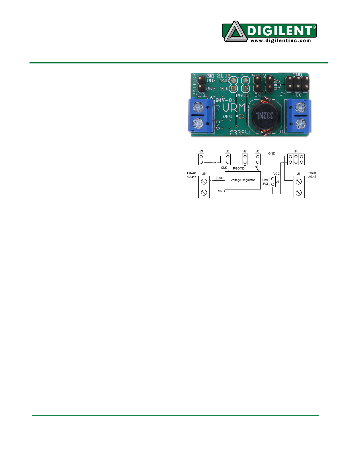
Board Circuit Diagram
Pullman, WA 99163
Input and Output Connections
The VRM board has power inputs and outputs
in both screw terminal and two-pin header
format. Connect the external power source to
the connections labeled “GND” and “VU” on
the screw terminal connector J6, or the two-pin
header, J3, labeled “BATTERY”. Observe
proper polarity in making the connections, as
reversed polarity will damage the VRM.
Digilent has battery packs available with
connectors suitable for the two-pin header.
Note: the screw terminal connector J6 is rated
for up to 10A of current but the two pin header
J3 is only rated for 2A. Do not use the VRM in
configurations where more than 2A of input
current will pass through J3.
Doc: 502-156 page 1 of 2
Copyright Digilent, Inc. All rights reserved. Other product and company names mentioned may be trademarks of their respective owners.
Page 2

Digilent VRM Reference Manual
The input current to the regulator is a function
of the voltage ratio between input and output
voltage, output current, and regulator
efficiency. The following formula applies:
Ii = ((Vo/Vi)*Io)/e
Where: Ii & Io are input and output current,
Vi & Vo are input and output voltage, and e is
the regulator efficiency. The efficiency depends
on several factors, but a value of 0.9 is
reasonable. Refer to the TI data sheet for the
TPS54620 for more information.
Screw terminal connector, J1, and the three
two-pin headers of J4 provide access to the
regulated output voltage. Digilent has available
two-wire MTE power cables that are ideal for
connections to the two-pin headers. As noted
above, the screw terminal connector is rated
for up to 10A, but the two pins headers are
only rated for 2A each. Do not attempt to draw
more than 2A on these connectors as they will
get very hot and may fail.
Observe proper polarity when connecting the
outputs of the VRM to the circuit being
powered. The polarity markings for J4 are on
the top of the board near J4. The polarity
markings for J1 are on the bottom of the board.
Jumper Options
Several jumpers are used to configure or
control the operation of the Digilent VRM:
Jumper J2 is used to select the output voltage.
Install a shorting block on J2 to select 3.3V
output. Otherwise the voltage output is 5V.
Connector J5 allows access to the enable input
to the regulator. This allows an external
controller, (such as a microcontroller) to turn
the regulator on or off. Driving the EN pin on
this connector to ground will turn off the
regulator. Allowing this pin to float will turn the
regulator on. The pin can also be used to
provide an undervoltage lockout. Refer to the
data sheet for the TPS54620 for more
information.
Connector J8 can be used to provide an
external clock signal to control the switching
frequency of the regulator. Connecting the CLK
pin on J8 to an external clock will cause the
VRM’s switching supply to synchronize to the
external clock source. The external clock must
be a square wave between 200kHz and
1600kHz. The amplitude of this signal must
transition below 0.8V and above 2.0V. If the
CLK pin is left disconnected, the supply will
switch at 479kHz.
Connector J7 provides access to the PGOOD
signal out of the regulator. The PGOOD pin on
J7 provides the status of the VRM output
voltage. This pin floats during normal
operation. The pin is driven low to indicate a
power supply fault. This occurs when the
VRM’s reference voltage is below 91% or
above 109% of normal. The PGOOD pin
should be connected to a pull-up resistor to
avoid erroneous fault detection.
www.digilentinc.com page 2 of 2
Copyright Digilent, Inc. All rights reserved. Other product and company names mentioned may be trademarks of their respective owners.
 Loading...