

Page 1
DDiiggiilleenntt SSeerrvvooMMiinnii™™ BBooaarrdd
RReeffeerreennccee MMaannuuaal
Revision: June 21, 2007
Overview
The Digilent ServoMini board is useful for
programmable control of up to eight RC servos
for both students and hobbyists.
The ServoMini’s versatile design and
programmable microcontroller allows you to
implement your own algorithms to control up to
eight RC servos. This allows you to decide
what method of control may be best suited for
your application.
The ServoMini can establish serial
communication with other devices using TWI
protocol from Atmel, or SPI. This enables you
to use the ServoMini as a slave device, freeing
up the workload of the master device. Using
TWI, many ServoMinis can be linked onto a
communication bus, giving it the ability to
expand with your needs.
The ServoMini can be powered using the
screw terminal connector, the SPI port or J12.
It supports a number of programming tools
including Atmel AVR® Studio 4, and WinAVR.
The device can be programmed using one of
Digilent’s programming cables.
Features include:
• ATmega168 microcontroller
• three LEDs
• ESD protection for all I/O pins
• in-system programming support using
the Digilent parallel JTAG cable or the
Digilent USB JTAG/SPI cable
• support for up to eight RC servos
• jumper selectable dedicated servo
power supply
• TWI bus daisy chain connectors
l
www.digilentinc.com
215 E Main Suite D | Pullman, WA 99163
(509) 334 6306 Voice and Fax
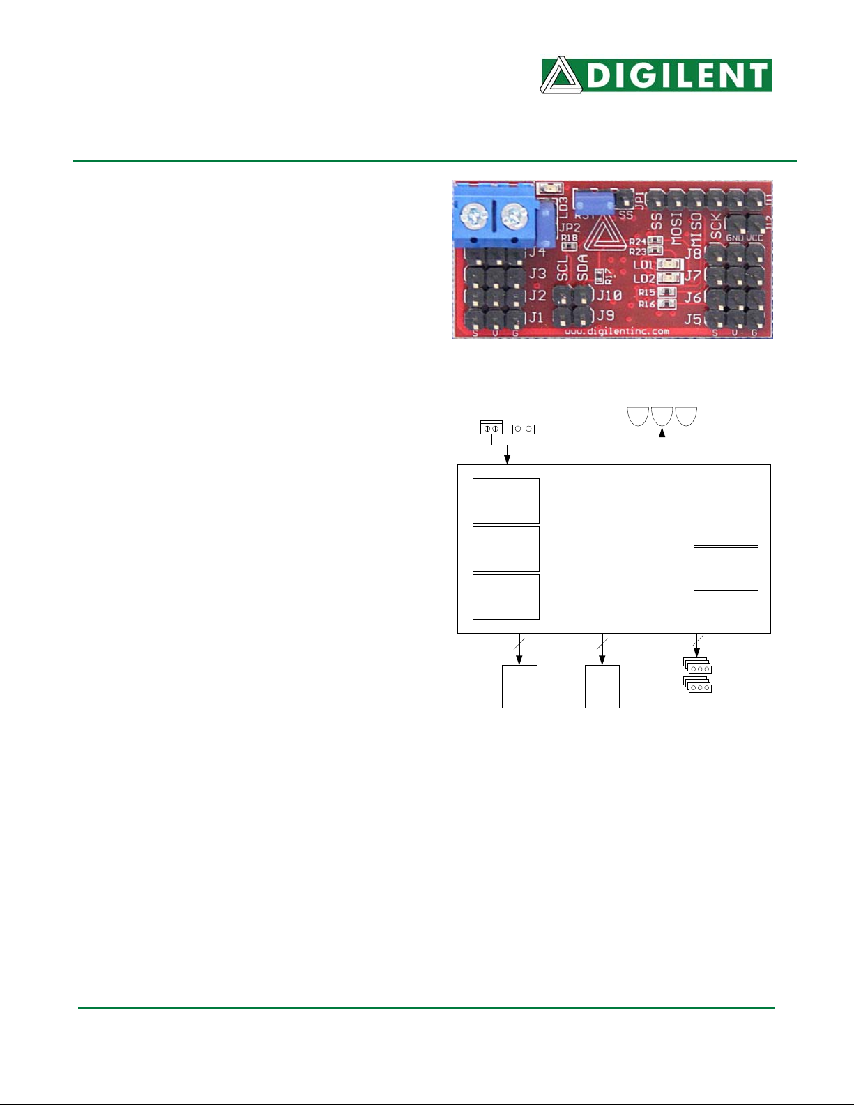
Figure 1 Digilent ServoMini Board
Various power
connectors
16k Flash
(Internal)
ATMega168
512 EEPROM
(Internal)
1k SRAM
(Internal)
4 4
J11
SPI/
ISP
Figure 2 Block Diagram
Features of the ATmega168 include:
• 16KB program flash
• 512 byte EEPROM
• 1KB internal SRAM
• master/slave serial peripheral interface
(SPI)
• Atmel two wire serial interface (TWI)
• 10-bit ADC analysis of the AVR power
supply along with the servo power
supply
• two 8-bit timer/counters
• one 16-bit timer/counter
MLF32
ServoMini
J9, J10
TWI
Chain
3 LEDs
Eight servo
connectors
®
Internal
Oscillator
SPI & TWI
ports
8
Doc: 502-102 1
Copyright Digilent, Inc. All rights reserved. Other product and company names mentioned may be trademarks of their respective owners.
Page 2

Digilent ServoMini Board Reference Manual
For more information about the
ATmega168, refer to the data sheet
available at www.atmel.com
.
Functional Description
The ServoMini is designed for embedded
control and robotic applications as well as
microprocessor experimentation. Embedded
firmware, suitable for many applications, can
be programmed into the ServoMini’s
ATmega168 microcontroller.
Although the ServoMini can be used as a
stand-alone microcontroller board, it is also
designed to be part of a larger system using
distributed processing architecture.
Connectors J9 and J10 allow it to be
connected to a serial data bus using Atmel’s
TWI protocol. In this case the ServoMini can
receive instructions, such as desired positions
for any of its eight servos, and then it can
interpret that data as the designer sees fit. It
can also transmit data, such as battery voltage
information, for processing by another
microcontroller.
The ServoMini’s firmware could also be
designed to monitor a few servo channels
coming from an RC receiver and drive servos
based on those pulse-widths. By doing this,
the ServoMini could be used as a servo mixer
or to control servos based on a custom
algorithm. The ServoMini’s servo driving ability
is only limited by the user’s imagination.
Power Supply Options
When a shorting block is installed on JP2, the
servos will share the same power supply as
the ServoMini’s processor. Power can be
applied via the screw terminal connector, via
connector J12 or pins 5 and 6 of the SPI
connector, J11. The Atmega168 processor is
rated for operation from 2.7 to 5.5 volts DC.
Using a voltage outside this range could
damage the ServoMini.
Digilent, Inc.
www.digilentinc.com
Alternatively, if jumper JP2 is removed, the
servos must have their own independent
power supply connected to the screw terminals
and the ServoMini’s processor must be
powered using either J12 or the SPI port.
Device Programming
The ServoMini has one in-systemprogramming connector, J11. The Digilent
programming cable is connected to J11. Either
a parallel JTAG or USB JTAB/SPI cable can
be used. When connecting the programming
cable, ensure that the VCC and GND pin
labels from the cable match to the VCC and
GND pins on the ServoMini.
A power supply must be provided to the
ServoMini when programming. The Digilent
programming cable does not supply power to
the board; the board it is plugged into powers
the programming cable. The Digilent
PmodREG1 voltage regulator module can be
used, or any appropriately regulated power
supply can be connected to J12. If the
ServoMini is being used in conjunction with
another Digilent board, such as the Cerebot or
Minicon, these boards have connectors that
can be used to supply power to the J12
connector on the ServoMini using a two-wire
cable.
Programming can be accomplished using the
Digilent AVRP application, available by free
download from the Digilent web site. It is also
possible to configure the AVRDUDE
programmer in the WinAVR release for insystem-programming using the Digilent parallel
JTAG cable. See the documentation for these
applications for more information on board
programming.
Connector J11 is used for both in-systemprogramming and for user access to the SPI
controller. The jumper block JP1 is used to
select between the two functions. The shorting
block is placed in the RST position for insystem-programming, and in the SS position
for user access to the SPI port.
www.digilentinc.com 2
Copyright Digilent, Inc. All rights reserved. Other product and company names mentioned may be trademarks of their respective owners.
Page 3

Digilent ServoMini Board Reference Manual
Two-Wire Serial Interface
The Atmel TWI interface is a medium speed
(400 Kbps), synchronous, serial,
communications bus. The TWI interface
supports master or slave operation with up to
128 devices on the bus. Each device is given
a unique address, and the protocol has the
ability to address packets to a specific device
or to broadcast packets to all devices on the
bus. For detailed information on configuring
and using the two-wire interface, see the
ATmega168 data sheet at www.atmel.com
.
The ServoMini connects to a TWI bus through
the 2-pin connector, J9 and J10. Attaching
these pins to a shared communications bus
can create a daisy chain of ServoMinis or other
TWI-capable boards.
The TWI bus is an open-collector bus.
Devices on the bus actively drive the signals
low. When no device is driving the lines low,
pull-up resistors achieve the high state on the
TWI lines. A single device on the TWI bus
must provide the pull-up resistors.
The ServoMini provides pull-up resistors that
are controlled by software. I/O port B, bits 6
and 7 (PB6 and PB7), are connected to the
pull-up resistors. To enable the pull-ups,
configure these pins as outputs and set the I/O
port output bits to “1”. To disable the pull-ups,
configure these pins as inputs with the internal
pull-ups disabled. Both TWI pull-ups should be
enabled or disabled together. Only one device
on the TWI bus should have pull-ups enabled.
A port bit is configured as an input or an output
by setting the corresponding bit in the DDR
register. The pin becomes an output by writing
a “1” and an input by writing a “0”. When a pin
is configured as an input, an internal pull-up
resistor is enabled by writing the corresponding
output port bit to “1” and disabled by writing it
to “0”. See the Atmel ATmega168 data sheet
for more information.
On-Board User I/O
Digilent, Inc.
www.digilentinc.com
The ServoMini provides three on-board LEDs
for user output. LEDs LD1 through LD3 are
connected to PB0, PB1 and PD3 respectively.
An LED is turned on by writing the pin to logic
1 and turned off by writing the pin to logic 0.
www.digilentinc.com 3
Copyright Digilent, Inc. All rights reserved. Other product and company names mentioned may be trademarks of their respective owners.
Page 4

Digilent ServoMini Board Reference Manual
Table 1: I/O connections
Location Description
Digilent, Inc.
www.digilentinc.com
J1 Servo 1
J2 Servo 2
J3 Servo 3
J4 Servo 4
J5 Servo 5
J6 Servo 6
J7 Servo 7
J8 Servo 8
J9 & J10 TWI connectors
The ATMEL TWI interface can be accessed on
this connector
J11 SPI interface and in-system-programming
When the shorting block on JP1 IS IN THE SS
position, J11 is used for the SPI port. When the
shorting block on JP1 is in the RST position, J11
is used for in-system-programming.
J12 Power supply
When JP2 is shorted, J12 supplies power to both
the MiniServo’s processor and the servos. When
JP2 is left open, J12 only supplies power to the
processor.
J13 Screw terminal Power supply
When JP2 is shorted, J13 can supply power to
both the processor and the servos. When JP2 is
left open, J13 becomes the dedicated servo
power supply.
LD1 LED 1
LD2 LED 2
LD3 LED 3
Programmable TWI pull-ups
Pin Function Port/bit
S ADC0 PC0
S ADC1 PC1
S ADC2 PC2
S ADC3 PC3
SAIN1 PD7
SAIN0 PD6
ST1 PD5
SXCK/T0 PD4
1 ADC5/SCL/PCINT13 PC5
2 ADC4/SDA/PCINT12 PC4
1 PCINT2/SS/OC1B PB2
2 PCINT3/OC2A/MOSI PB3
3 PCINT4/MISO PB4
4 SCK/PCINT5 PB5
5 GND
6 VCC
1 GND
2 VCC
1 SVCC
2 GND
ICP1 PB0
OC1A PB1
INT1 PD3
1 XTAL1/TOSC1 PB6
2 XTAL2/TOSC2 PB7
www.digilentinc.com 4
Copyright Digilent, Inc. All rights reserved. Other product and company names mentioned may be trademarks of their respective owners.
 Loading...