

Page 1
DDiiggiilleenntt PPmmooddUUSSBB22 MMoodduullee
BBooaarrdd RReeffeerreennccee MMaannuuaal
Revision: 3/11/05 215 E Main Suite D | Pullman, WA 99163
l
www.digilentinc.com
(509) 334 6306 Voice and Fax
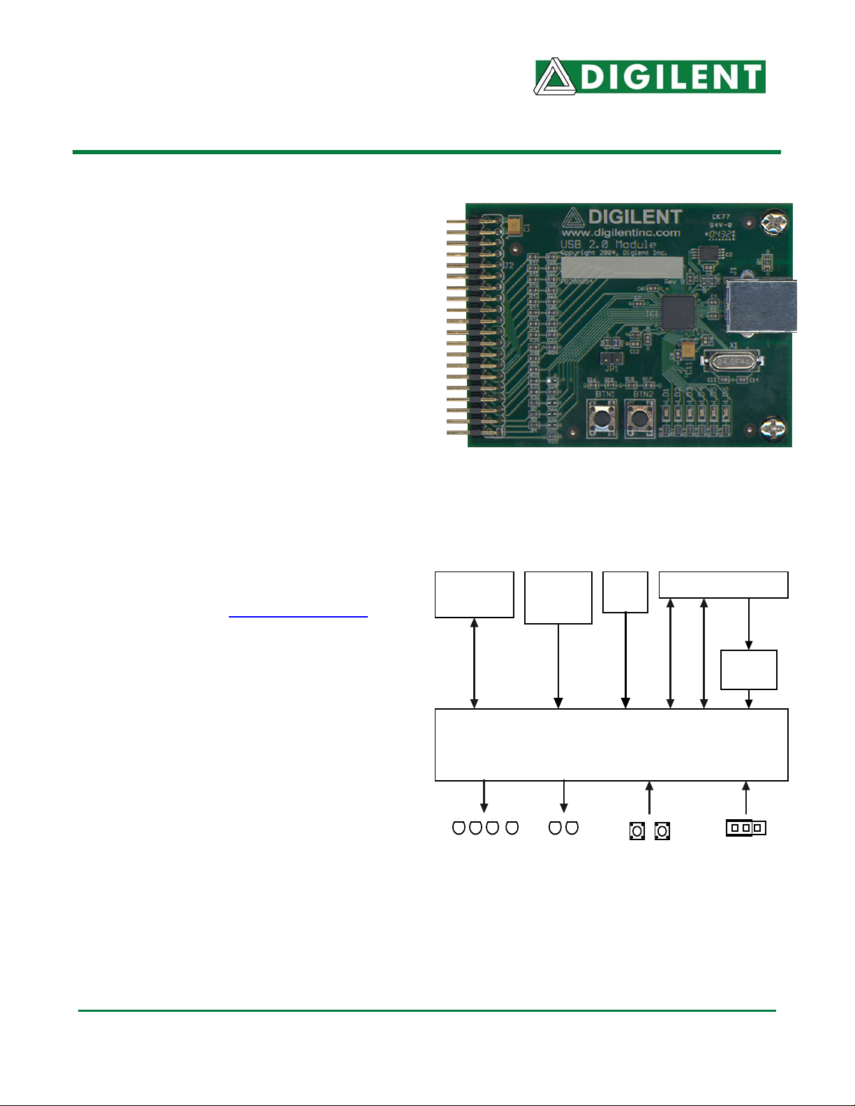
Overview
The Digilent PmodUSB2 Module Board (the
USB2) is used to create a USB 2.0 connection
on any Digilent system board.
The USB2 is based on the Cypress
CY7C68013 USB controller and can be used
to configure system boards or exchange data
with a PC.
Digilent firmware in the Cypress USB controller
works with Digilent’s PC-based Adept software
to coordinate JTAG programming and user
data transfers. The data port uses a protocol
similar to the 14-signal “Enhanced Parallel
Port” (EPP) protocol.
The USB2 is compatible with all newer Digilent
system boards including the Spartan-3,
Pegasus, D2SB™, and D2FT™ boards. It can
also be used with the older D2 and D2E
boards for user data transfers, but not for
programming. For more information, see the
reference manuals at www.digilentinc.com
Features include:
• USB 2.0 connector
• status indicator LED
• Cypress CY7C68013 USB controller
• small form factor (3.00” x 2.20”).
.
Type B USB
Connector
Microchip
EEPROM
24AA128
Crystal
(24Mhz)
Expansion Connector
Module Bus
Cypress CY7C68013
JTAG
Regulator
3.3V
2.5VDC
Functional Description
The USB2’s Cypress USB controller is a
convenient USB 2.0 connection solution that
includes the USB interface and an 8051-based
processor.
Digilent firmware in the Cypress USB controller
uses a packet-transfer protocol for JTAG
programming and user data transfers.
Digilent’s Adept Suite software includes two
application programs, Export (for JTAG
4 User
LEDs
2 Status
LEDs
USB2 Circuit Diagram
2 Pushbuttons
1 Jumper
(Config Reset)
®
Doc: 500-054 page 1 of 1
Copyright Digilent, Inc. All rights reserved. Other product and company names mentioned may be trademarks of their respective owners.
Page 2

Digilent USB2 Reference Manual Digilent, Inc.
programming) and Transport (for user data
transfers).
For JTAG programming, the Adept software
can transfer .bit or .svf files directly to the
Cypress USB controller where firmware then
drives the JTAG scan chain. For more
information see the Digilent Adept Reference
Manual at www.digilentinc.com
For data transfer between a system board and
an attached PC, Digilent’s Adept Software
Developers Kit contains the necessary DLLs,
APIs, and Windows drivers to allow users to
create their own USB2 transport applications.
Digilent also provides a VHDL reference
design. The VHDL source file “dpimref.vhd” is
available as a separate download. See the
Digilent Software Development Kit, the Digilent
Port Communications Reference Manual, and
the Digilent Parallel Interface Model Reference
Manual. They can all be downloaded from
www.digilentinc.com
The firmware in the Cypress USB controller
can be modified using the Cypress EZ-USB
Development kit available from Cypress. For
more information, see www.cypress.com
Digilent does not offer user support for
modifying the firmware.
USB2 Communications
The Adept software manages communications
with the USB2. It can identify a particular USB2
module using either a serial number or an ID
string. A unique serial number and the default
ID string “DModUsb” are programmed into the
USB2 and the serial number is printed on a
label affixed to the module. Digilent provides a
“USB Administrator” tool as part of the Adept
software that can be used to modify the 16character ID string. See the Digilent Adept
Reference Manual for more information.
.
.
.
Communications Module dialog box in the
Adept Suite. See the Digilent Adept Reference
Manual for more information.
The USB2 should be connected to a system
board’s A1, B1, or C1 expansion connectors
for proper operation. It can be connected to
other expansion connectors, but JTAG
programming will not be available. It is
recommended that the system board be turned
off prior to connecting the module.
User I/O Devices
The USB2 contains several I/O devices,
including six status LEDs, two debounce
pushbuttons, and one 2-pin jumper.
Pushbuttons and Jumper
The pushbuttons and jumper are not used by
the Digilent firmware on the Cypress USB
controller, but they can be configured as inputs
with the Cypress EZ-USB Development Kit.
Status LEDs
LED1: Indicates that the Digilent firmware is
loaded and ready.
LED2: Indicates data activity on the USB2
Module.
LED3-6: Not currently used. They can be
configured as user outputs with the Cypress
EZ-USB Development Kit.
The USB2 can be used for JTAG programming
or user data transfers only after it has been
identified within the Adept software. The USB2
is identified by adding its serial number or ID
string to a Device Table accessed through the
www.digilentinc.com page 2 of 2
Copyright Digilent, Inc. All rights reserved. Other product and company names mentioned may be trademarks of their respective owners.
Page 3

Digilent USB2 Reference Manual Digilent, Inc.
Useful Downloads
The following items are all available for free
from www.digilentinc.com
Documents
• Digilent Adept Reference Manual
• Digilent Port Communications Reference
Manual
• Digilent Parallel Interface Model Reference
Manual
• Digilent JTAG Scan Reference Manual
Software
• Digilent Adept Suite
• Digilent Adept Software Developers Kit
Reference Designs
• VHDL source file “dpimref.vhd”
.
Pinout Table
The table below provides the pin assignments
for the expansion connector.
Pin # Signal
1 TDI
2 TDO
3 TMS
4 TCK
5 INT
6 JTSEL
7 WAIT
8 RESET
9 /DSTB
10 WRITE
11 DB7
12 ASTB
13 DB5
14 DB6
15 DB3
16 DB4
17 DB1
18 DB2
19
20 DB0
21
22
23
24
25
26
27
28
29
30
31
32
33
34
35
36
37 VDD33
38
39 GND
40
www.digilentinc.com page 3 of 3
Copyright Digilent, Inc. All rights reserved. Other product and company names mentioned may be trademarks of their respective owners.
 Loading...