

Page 1
1300 Henley Court
Pullman, WA 99163
509.334.6306
www.digilentinc.com
PmodTMP2™ Reference Manual
Revised May 24, 2016
This manual applies to the PmodTMP2 rev. B
DOC#: 502-221
Copyright Digilent, Inc. All rights reserved.
Other product and company names mentioned may be trademarks of their respective owners.
Page 1 of 3
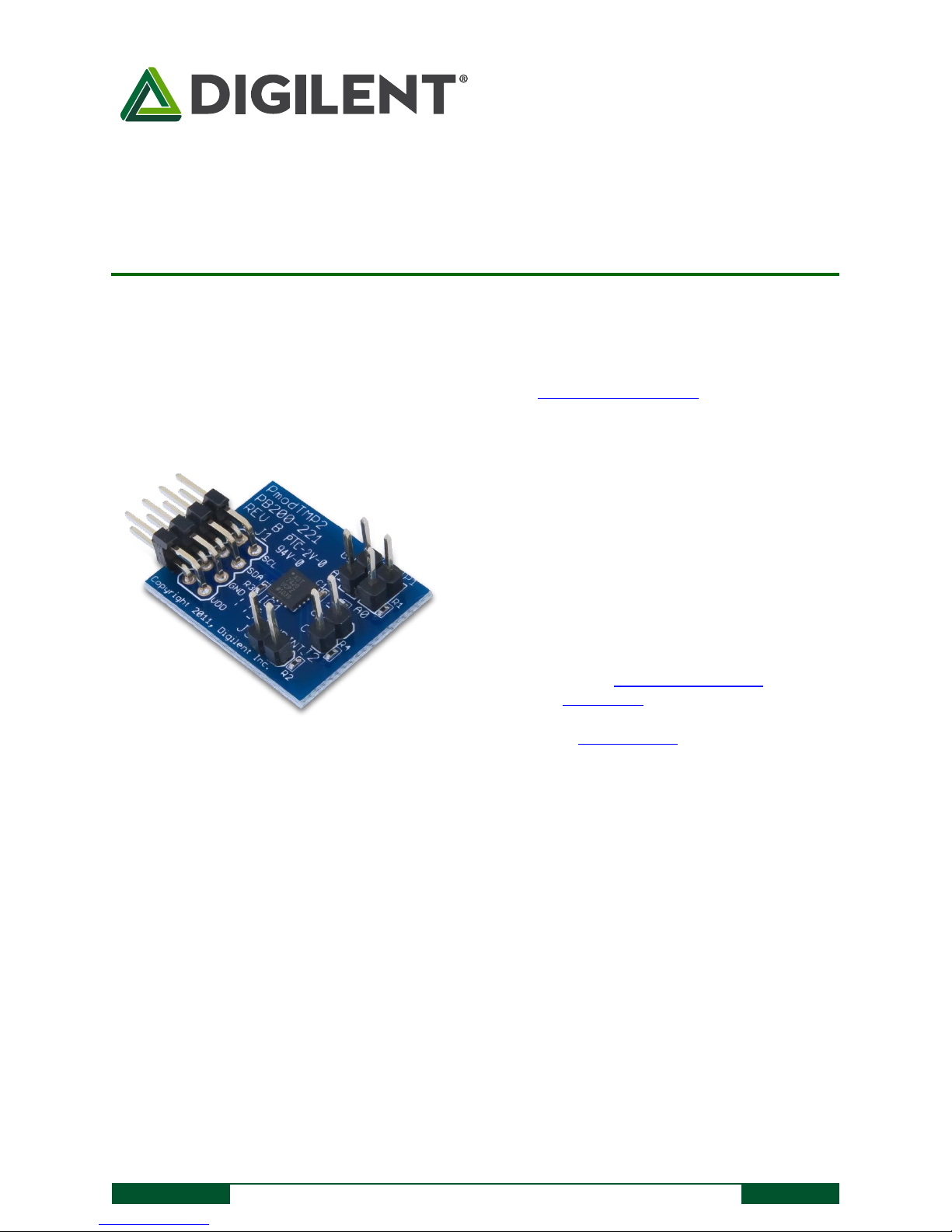
The PmodTMP2.
16-bit ambient temperature sensor
Typical accuracy better that 0.25ºC
240 ms continuous conversion time
Programmable over and under-
temperature control pins
No calibration required
Small PCB size for flexible designs 1.0“ ×
0.8” (2.5 cm × 2.0 cm)
2×4-pin connector with I2C interface
Follows Digilent Pmod Interface
Specification
Library and example code available
in resource center
Features include:
Overview
The PmodTMP2 is an ambient temperature sensor powered by the Analog Devices® ADT7420. Through the I2C
interface, users may appreciate a resolution of 0.0078°C through 16 bits of data.
1 Functional Description
The PmodTMP2 uses an 8-pin connector that allows for communication via I2C, and provides pins to daisy-chain
the PmodTMP2 to other I2C devices. The PmodTMP2 also provides two 2-pin headers for selecting the I2C address
of the chip, and two 2-pin headers for controlling external devices based upon temperature thresholds defined by
the user in software.
2 Interfacing with the Pmod
The PmodTMP2’s onboard ADT7420 chip acts as a slave device using the industry standard I2C communication
scheme. To communicate with the PmodTMP2 device the I2C master device must specify a slave address (0x480x4B) and a flag indicating whether the communication is a read (1) or a write (0). This is followed by the actual
data transfer. For the ADT7420, the data transfer should consist of the address of the desired device register
followed by the data to be written to the specified register. To read from a register the master must write the
desired register address to ADT7420, then send an I2C restart condition, and send a new read request to the
Page 2

PmodTMP2™ Reference Manual
Copyright Digilent, Inc. All rights reserved.
Other product and company names mentioned may be trademarks of their respective owners.
Page 2 of 3
Connector J1 – I2C Communications
Pin
Signal
Description
1, 2
SCL
I2C Clock
3, 4
SDA
I2C Data
5, 6
GND
Power Supply Ground
7, 8
VCC
Power Supply (3.3V/5V)
Header J1 Jumper Blocks
Pin
Signal
Description
Jumper Block
State
Description
1 & 5
SCL
Serial Clock
JP1
Open/Shorted
Address bit 0 high/low
2 & 6
SDA
Serial Data
JP2
Open/Shorted
Address bit 1 high/low
3 & 7
GND
Power Supply Ground
User Outputs
4 & 8
VCC
Positive Power Supply
Header Name
Pin Name
Description
J2
CT
Critical Threshold Output
J3
INT
Interrupt Output
Addresses
JP2
JP1
Address
Open
Open
0x4B (0b1001011)
Open
Shorted
0x4A (0b1001010)
Shorted
Open
0x49 (0b1001001)
Shorted
Shorted
0x48 (0b1001000)
ADT7420. If the master does not generate a restart condition prior to attempting the read, then the value written
to the address register will be reset to 0x00.
As some registers stored 16-bit values as 8-bit register pairs, the ADT7420 will automatically increment the address
register of the device when accessing certain registers such as the temperature registers and the threshold
registers. This allows for the master to use a single read or write request to access both the low and high bytes of
these registers. A complete listing of registers and their behavior can be found in the ADT7420 datasheet available
on the Analog Devices web site.
Table 1. Interface connector signal description.
Table 2. Pinout description table.
The I2C interface standard uses two signal lines. These are I2C data and I2C clock. These signals map to the serial
data (SDA) and serial clock (SCL) respectively on the ADT7420.
Table 3. I2C address selection.
The PmodTMP2 I2C bus can be set to use one of four valid addresses. The top five bits of the address are fixed, and
the two least significant bits are taken from the jumper states of JP2 and JP1. JP2 corresponds to bit one of the
address while JP1 corresponds to bit zero. An open jumper corresponds to a one in the address while a shorted
jumper corresponds to a zero. For example, when JP2 and JP1 are open the device uses the address 0x4B
(0b1001011).
Page 3

PmodTMP2™ Reference Manual
Copyright Digilent, Inc. All rights reserved.
Other product and company names mentioned may be trademarks of their respective owners.
Page 3 of 3
2.1 Open Drain Outputs
The PmodTMP2 provides two open drain output headers for controlling external devices based upon current
temperature thresholds. If the temperature leaves a range defined by registers T
(0x06:0x07) and T
LOW
HIGH
(0x04:0x05) then the INT pin on J3 can be driven low or high based upon the configuration of the device. Similarly,
the CT pin on J2 can be driven low or high if the temperature exceeds a critical threshold defined in T
CRIT
(0x08:0x09). Both of these pins are pulled up by 10KOhm resistors when they are not driven by the device. For
details on their electrical specifications and configuration of the INT and CT pins please refer to the ADT7420
datasheet.
2.2 Quick Start Operation
When the PmodTMP2 is powered up, the onboard ADT7420 is in a mode that can be used as a simple temperature
sensor without any initial configuration. By default, the device address register points to the temperature MSB
register, so a two byte read without specifying a register will read the value of the temperature register from the
device. The first byte read back will be the most significant byte (MSB) of the temperature data, and the second
will be the least significant byte (LSB) of the data. These two bytes form a two’s complement 16-bit integer, if the
result is shifted to the right three bits and multiplied by 0.0625 the resulting signed floating point value will be a
temperature reading in degrees Celsius.
For information on reading and writing to the other registers of the device, as well as notes on the accuracy of the
temperature measurements please refer to the ADT7420 datasheet.
Page 4

Mouser Electronics
Authorized Distributor
Click to View Pricing, Inventory, Delivery & Lifecycle Information:
Digilent:
410-221P 410-221
 Loading...