

Page 1
PPmmooddRRSS223322XX™
RReeffeerreennccee MMaannuuaal
Revision: July 30, 2012
Note: This document applies to REV A of the board.
™
l
Overview
The PmodRS232X Converter Module
translates voltage from the logic levels used by
Digilent system boards to the RS232 voltage
used for serial communications.
The PmodRS232X creates a two-way I/O
exchange by converting RS232 voltage to
logic-level voltage and converting logic voltage
to RS232 voltage. RS232 voltage levels are -3
to -12V for a logic ‘1’, and +3 to +12 for a logic
‘0’.
The PmodRS232X is configured as a data
communications equipment (DCE) device. It
connects to data terminal equipment (DTE)
devices, such as the serial port on a PC, using
a straight-through cable.
Features include:
• an Analog Devices ADM3232ERS232
transceiver
• a DB9 connector and 6-pin header
• transmit and receive data functions
• optional RTS and CTS handshaking
functions
• small form factor (1.00” x 1.30”)
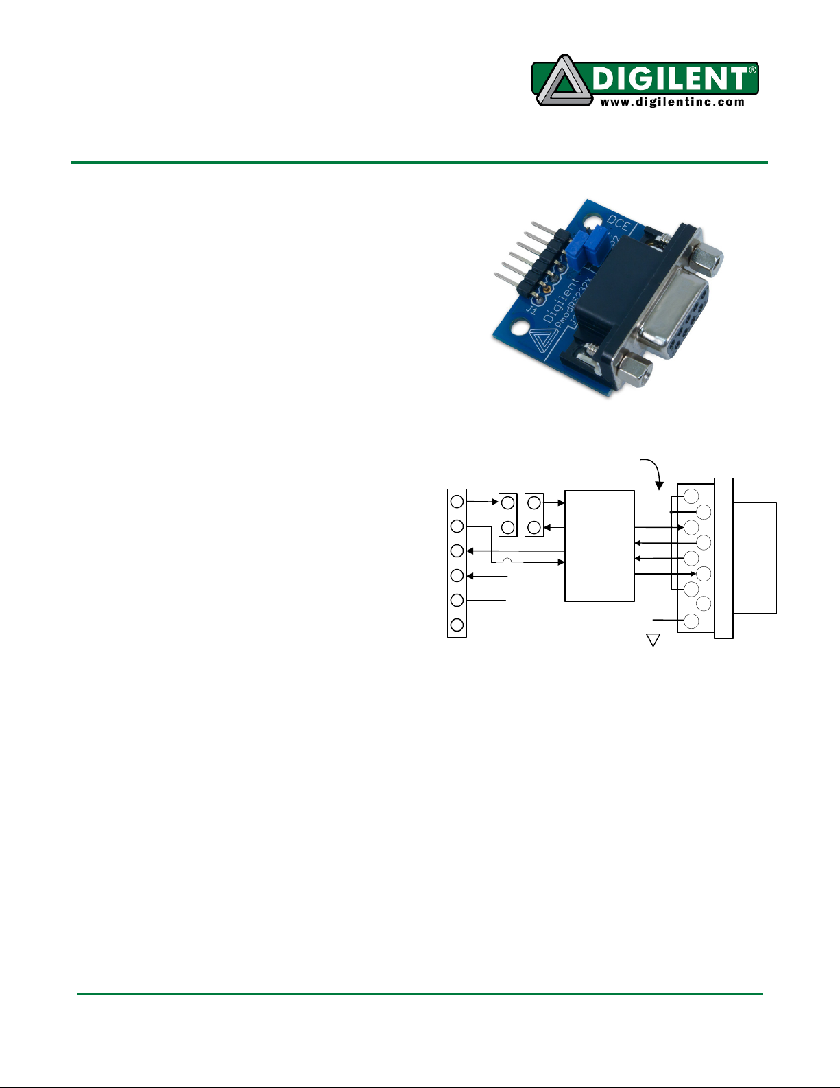
Functional Description
The RS232 module provides two transmit
buffers and two receive buffers. A transmit
buffer converts a logic-level signal on its input
to an RS232 voltage-level signal on its output.
A receive buffer converts an RS232 voltagelevel signal on its input to a logic-level signal
on its output.
The RS232 module can be configured as
either a 3-wire DTE serial port (with one
transmitter for transmit-data signals, one
receiver for receive-data signals, and a signal-
1300 NE Henley Court, Suite 3
(509) 334 6306 Voice | (509) 334 6300 Fax
Pins 1,4,6 are tied
for handshaking.
JP1 JP2
CTS
1
RXD
2
TXD
3
RTS
4
5
6
GND
VCC
J1
Pullman, WA 99163
Analog
Devices
ADM3232E
RS232
Transceiver
NC
1
6
2
7
3
8
4
9
5
RS232 Module Block Diagram
ground connection), or as a 5-wire DTE serial
port with an additional transmitter and receiver
for RTS and CTS handshaking signals,
respectively.
The PmodRS232X is designed to work with
either Digilent programmable logic system
boards or embedded control boards. Most
Digilent system boards (like the Basys, Nexys,
or Cerebot) have 6-pin connectors that allow
the PmodRS232X to plug directly into the
system board or to connect via a Digilent 6-pin
cable.
DB9
DCE Connector
Doc: 502-240 page 1 of 2
Copyright Digilent, Inc. All rights reserved. Other product and company names mentioned may be trademarks of their respective owners.
Page 2
PmodRS232X Reference Manual
Some older Digilent boards may need a
Digilent Module Interface Board (MIB) and a 6pin cable to connect to the PmodRS232X. The
MIB plugs into the system board and the cable
connects the MIB to the PmodRS232X.
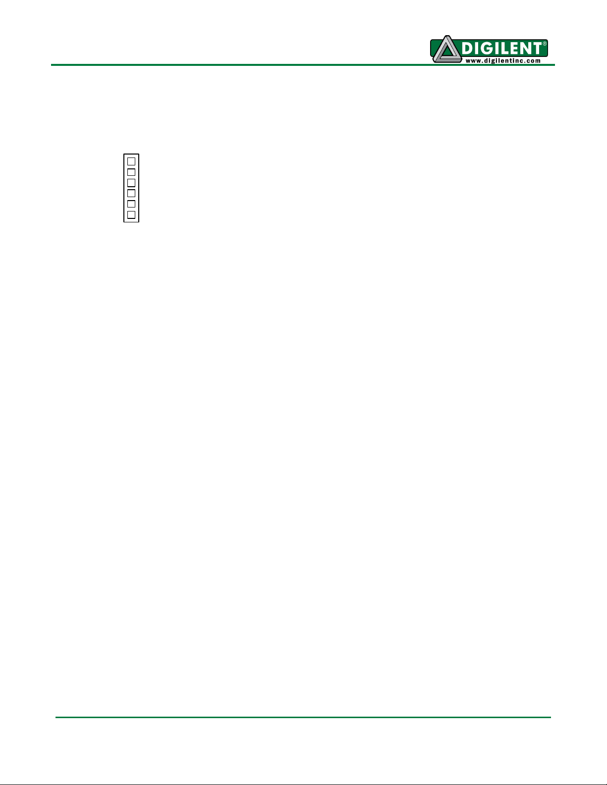
(1) CTS
(2) RXD
(3) TXD
(4) RTS
(5) GND
(6) Vcc (3.3 - 5V)
RS232 Module Connector J1
The RS232 module is wired as a DTE device.
RS232 signals are named from the perspective
of the DCE. The TXD signal carries data from
the DCE to the DTE. Therefore, the TXD signal
on pin 3 is connected to the output of a
receiver and should be connected to the
receive input of a UART on the system board.
Similarly, the RXD signal carries data from the
DTE to the DCE and is connected to the input
of a transmitter on the RS232 module and
should be connected to the output of the UART
on the system board.
The CTS signal on pin 1 can be connected to
the input of a transmitter and the RTS signal
on pin 4 can be connected to the output of a
receiver. These connections are made using
jumper blocks JP1 and JP2, as described
below.
Digilent embedded control boards, like the
Cerebot, have one or more connectors with the
UART signals configured correctly for direct
connection of the RS232 module. On Digilent
programmable logic boards like the Basys or
Nexys, a UART must be defined in the logic of
the FPGA or CPLD and the appropriate signal
connections must be defined to connect the
UART to the appropriate connector pins.
Using Jumper Blocks JP1 and JP2
Jumper blocks JP1 and JP2 are used to
configure the RS232 module for either 3-wire
or 5-wire operation. Pins 1 and 2 of JP1 are
connected to pins 1 and 4 of connector J1,
respectively. Pins 1 and 2 of JP2 are
connected to the CTS transmitter and the RTS
receiver, respectively.
To configure the RS232 module as a 3-wire
DTE with no handshaking, place a shorting
block across the two pins of JP2 and ensure
there’s no shorting block on JP1. This loops
RTS back to CTS on the RS232 side of the
module and leaves pins 1 and 4 unconnected
on J1.
To configure the RS232 module as a 5-wire
DTE with RTS/CTS handshaking, place a
shorting block across pin 1 of JP1 and pin 1 of
JP2, and place another shorting block across
pin 2 of JP1 and pin 2 of JP2. This connects
the CTS transmitter to pin 1 of J1 and the RTS
receiver to pin 4 of J1.
www.digilentinc.com page 2 of 2
Copyright Digilent, Inc. All rights reserved. Other product and company names mentioned may be trademarks of their respective owners.
 Loading...