

Page 1
PPmmooddRRFF11™
Revision: December 18, 2009
Note: This document applies to Rev A of the board.
™ RReeffeerreennccee MMaannuuaall
215 E Main Suite D | Pullman, WA 99163
(509) 334 6306 Voice and Fax
Overview
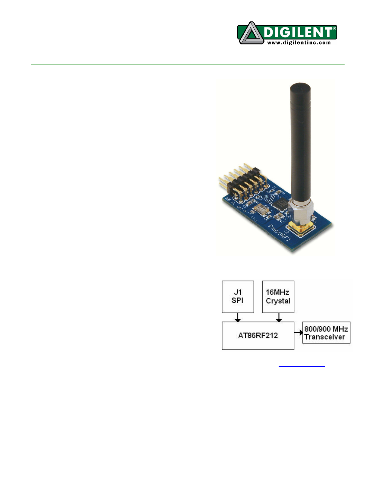
The PmodRF1 is a radio transceiver that can be selectively
configured to operate in the open 902MHz to 928MHz ISM
band for use in North America, the European SRD Band of
863MHz to 870MHz, or the Chinese WPAN band of
779MHz to 787MHz. This flexibility ensures that users from
many parts of the world can safely use this one product in
applications requiring wireless communication.
The PmodRF1 features the Atmel AT86RF212, a lowpower, long-range radio transceiver. Atmel's partner,
Meshnetics, independently verified that the transceiver is
capable of communicating at a range of 6km, but the
effective range will depend on a variety of factors, such as
antenna selection, line-of-sight, and other environmental
obstructions.
The board also features an SMA connector, which allows
users to select the antenna that best suits their application.
Atmel makes software libraries that enable users to
implement 6LoWPAN, ZigBee PRO, and IEEE 802.15.4based networks using the AT86RF212 transceiver.
Functional Description
The main communications interface for the PmodRF1 is an
SPI bus accessible via J1. The PmodRF1 implements an SPI
slave interface set up in Mode 0, MSB first. The PmodRF1
also offers an interrupt request signal, reset, multipurpose
control signal, and an output clock driver on the J1 header.
Refer to the PmodRF1 schematic available on the Digilent
website for more information about the hardware
connections.
For more information on the Atmel AT86RF212, refer to the data sheet available at www.atmel.com.
Doc: 502-159 page 1 of 2
Copyright Digilent, Inc. All rights reserved. Other product and company names mentioned may be trademarks of their respective owners.
Page 2
PmodRF1 Reference Manual
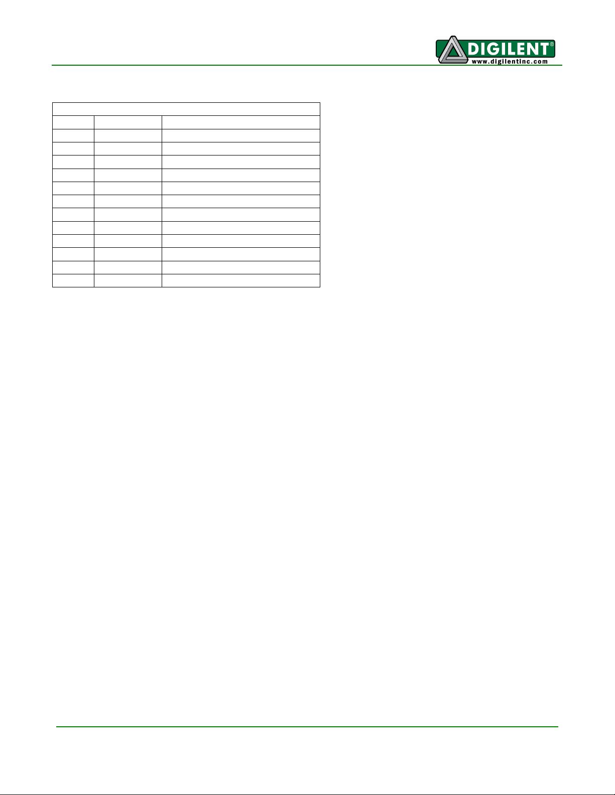
Connector J1 – SPI Communications
Pin Signal Description
1 SEL Slave Select
2 MOSI Master out/Slave in Data
3 MISO Master in/Slave out Data
4 SCLK Serial Clock
5 GND Power Supply Ground
6 VCC Power Supply (3.3V)
7 IRQ Interrupt Request Signal
8 RST Hardware Reset (Active Low)
9 SLP_TR Multipurpose Control Signal
10 CLKM Clock Output
11 GND Power Supply Ground
12 VCC Power Supply (3.3V)
www.digilentinc.com page 2 of 2
Copyright Digilent, Inc. All rights reserved. Other product and company names mentioned may be trademarks of their respective owners.
 Loading...