

Page 1
1300 Henley Court
Pullman, WA 99163
509.334.6306
www.digilentinc.com
PmodPS/2™ Reference Manual
Revised May 26, 2016
This manual applies to the PmodPS/2 rev. C
DOC#: 502-094
Copyright Digilent, Inc. All rights reserved.
Other product and company names mentioned may be trademarks of their respective owners.
Page 1 of 4
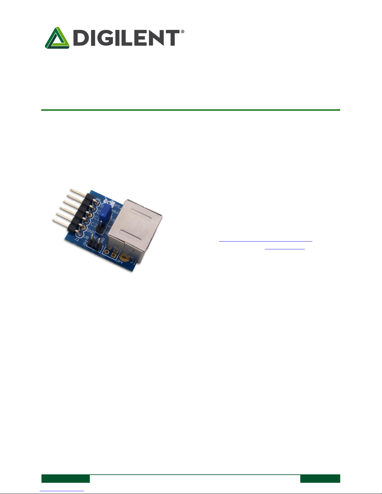
The PmodPS/2.
Standard PS/2 port
Jumper to allow for an external power source
Small PCB size for flexible designs 1.0“ × 0.8” (2.5 cm ×
2.0 cm)
6-pin Pmod connector with GPIO interface
Follows Digilent Pmod Interface Specification Type 1
Example code available in resource center
Features include:
Overview
The Digilent PmodPS/2 is a module that allows users to attach a PS/2 compatible keyboard or mouse to their
system board.
1 Functional Description
The PmodPS/2 module is a standard PS/2 connector that by nature of the PS/2 supports N-KEY rollover. This is a
feature that guarantees that every movement and key press will be received and addressed. Naturally, whether or
not the key press will actually perform a function is dependent on the software, but the system board will still
receive all of the inputs.
2 Interfacing with the Pmod
The PmodPS/2 communicates with the host board via the GPIO protocol. Both the keyboard and mouse will use a
data and a clock line to communicate their information to the system board. Specific details on how this is done
are available in their respective sections below.
Page 2
PmodPS/2™ Reference Manual
Copyright Digilent, Inc. All rights reserved.
Other product and company names mentioned may be trademarks of their respective owners.
Page 2 of 4
Pin Number
Description
1
Data
2
Not Used
3
Clock
4
Not Used
5
Ground
6
VCC
PS/2
Connector
Pin 1
Pin 5Pin 6
Bottom-up
hole pattern
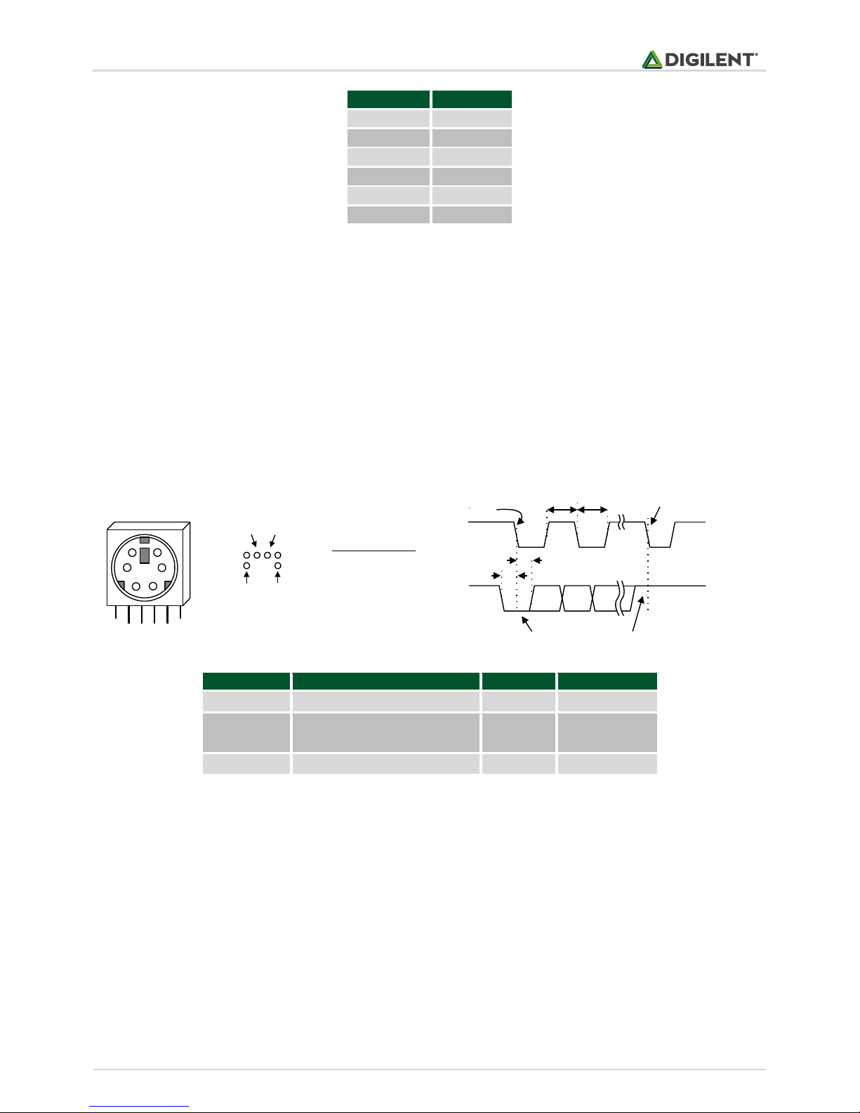
Pin Definitions
Pin Function
1 Data
2 Reserved
3 GND
4 Vdd
5 Clock
6 Reserved
1
5
3
2
4
6
Pin 2
T
CK
T
SU
Edge 0
Edge 10
CLK
DATA
T
HLD
T
CK
'1' stop bit'0' start bit
Symbol
Parameter
Min
Max
Tck
Clock time
30us
50us
Tsu
Data-to-clock setup time
5us
25us
Thld
Clock-to-data hold time
5us
25us
Table 1. Pin description table.
3 Keyboard and Mouse Interface
The keyboard and mouse both use identical signal timings. Both use 11-bit words that include a start, stop, and
odd parity bit, but the data packets are organized differently, and the keyboard interface allows bi-directional data
transfers (so the host device can illuminate state LEDs on the keyboard). Bus timings are shown below. The clock
and data signals are only driven when data transfers occur, and otherwise they are held in the “idle” state at logic
‘1’. The timings define signal requirements for mouse-to-host communications and bi-directional keyboard
communications.
3.1 Keyboard
The keyboard uses open-collector drivers so that either the keyboard or an attached host device can drive the twowire bus (if the host device will not send data to the keyboard, then the host can use simple input-only ports).
PS/2-style keyboards use scan codes to communicate key-press data (nearly all keyboards in use today are PS/2
style). Each key has a single, unique scan code that is sent whenever the corresponding key is pressed. If the key is
pressed and held, the scan code will be sent repeatedly once every 100ms or so. When a key is released, an “F0”
key-up code is sent, followed by the scan code of the released key. If a key can be “shifted” to produce a new
character (like a capital letter), then a shift character is sent in addition to the original scan code, and the host
device must determine which character to use. Some keys, called extended keys, send an “E0” ahead of the scan
Table 2. Bus timings.
Page 3

PmodPS/2™ Reference Manual
Copyright Digilent, Inc. All rights reserved.
Other product and company names mentioned may be trademarks of their respective owners.
Page 3 of 4
ED
Set Num Lock, Caps Lock, and Scroll Lock LEDs. After receiving an “ED”, the keyboard returns an “FA”, then
the host sends a byte to set LED status. Bit 0 sets Scroll Lock, bit 1 sets Num Lock; and Bit 2 sets Caps lock. Bits
3 to 7 are ignored.
EE
Echo. Upon receiving an echo command, the keyboard replies with “EE”.
F3
Set scan code repeat rate. The keyboard acknowledges receipt of an “F3” by returning an “FA”, after which
the host sends a second byte
FE
Resend. Upon recieving FE, the keyboard re-sends the last scan code sent.
FF
Reset. Resets the keyboard.
ESC
76
` ~
0E
TAB
0D
Caps Lock
58
Shift
12
Ctrl
14
1 !162 @1E3 #264 $255 %
2E
Q
15W1DE24R2DT2C
A
1CS1BD23F2BG34
Z
1ZX22C21V2AB32
6 ^367 &3D8 *3E9 (460 )45- _4E= +55BackSpace
66
Y
35U3CI43O44P4D
[ {
54
] }
5B
\ |
5D
H
33J3BK42L4B
; :
4C
' "
52
Enter
5A
N
31M3A
, <41> .49/ ?
4A
Shift
59
Alt
11
Space
29
Alt
E0 11
Ctrl
E0 14
F105F206F304F4
0C
F503F60BF783F8
0A
F901F1009F1178F12
07
E0 75
E0 74
E0 6B
E0 72
code (and they may send more than one scan code). When an extended key is released, an “E0 F0” key-up code is
sent, followed by the scan code. Scan codes for most keys are shown in the keyboard diagram below.
A host device can also send data to the keyboard. Below is a short list of some oft-used commands.
Table 3. Common commands.
The keyboard sends data to the host only when both the data and clock lines are high (or idle). Since the host is the
“bus master”, the keyboard checks to see whether the host is sending data before driving the bus. To facilitate
this, the clock line can be used as a “clear to send” signal. If the host pulls the clock line low, the keyboard will not
send any data until the clock is released.
The keyboard sends data to the host in 11-bit words that contain a ‘0’ start bit, followed by 8-bits of scan code (LSB
first), followed by an odd parity bit and terminated with a ‘1’ stop bit. The keyboard generates 11 clock transitions
(at around 20 – 30kHz) when the data is sent, and data is valid on the falling edge of the clock.
3.2 Mouse
The mouse outputs a clock and data signal when it is moved, otherwise these signals remain at logic ‘1’. Each time
the mouse is moved, three 11-bit words are sent from the mouse to the host device. Each of the 11-bit words
contains a ‘0’ start bit, followed by 8 bits of data (LSB first), followed by an odd parity bit, and terminated with a ‘1’
stop bit. Thus, each data transmission contains 33 bits, where bits 0, 11, and 22 are ‘0’ start bits, and bits 11, 21,
and 33 are ‘1’ stop bits. The three 8-bit data fields contain movement data as shown below. Data is valid at the
falling edge of the clock, and the clock period is 20 to 30kHz.
Page 4

PmodPS/2™ Reference Manual
Copyright Digilent, Inc. All rights reserved.
Other product and company names mentioned may be trademarks of their respective owners.
Page 4 of 4
L R 0 1 XS YS XY YY P X0 X1 X2 X3 X4 X5 X6 X7 P Y0 Y1 Y2 Y3 Y4 Y5 Y6 Y7 P1 0 1 00 11
Idle state
Start bit Stop bit
Start bit
Mouse status byte X direction byte Y direction byte
Stop bit
Start bit
Stop bit
Idle state
The mouse assumes a relative coordinate system wherein moving the mouse to the right generates a positive
number in the X field, and moving to the left generates a negative number. Likewise, moving the mouse up
generates a positive number in the Y field, and moving down represents a negative number (the XS and YS bits in
the status byte are the sign bits – a ‘1’ indicates a negative number). The magnitude of the X and Y numbers
represent the rate of mouse movement – the larger the number, the faster the mouse is moving (the XV and YV
bits in the status byte are movement overflow indicators – a ‘1’ means overflow has occurred). If the mouse moves
continuously, the 33-bit transmissions are repeated every 50ms or so. The L and R fields in the status byte indicate
Left and Right button presses (a ‘1’ indicates the button is being pressed).
4 Physical Dimensions
The pins on the pin header are spaced 100 mil apart. The PCB is 1 inch long on the sides parallel to the pins on the
pin header and 0.8 inches long on the sides perpendicular to the pin header.
Page 5

Mouser Electronics
Authorized Distributor
Click to View Pricing, Inventory, Delivery & Lifecycle Information:
Digilent:
410-094P 410-094
 Loading...