


1300 Henley Court
Pullman, WA 99163
509.334.6306
www.digilentinc.com
PmodISNS20™ Reference Manual
Revised April 12, 2016
This manual applies to the PmodISNS20 rev. A
DOC#: 502-325
Copyright Digilent, Inc. All rights reserved.
Other product and company names mentioned may be trademarks of their respective owners.
Page 1 of 3
The PmodISNS20.
High accuracy current sensor
Measure current with 120Hz/20kHz/80kHz
jumper selections
±20A DC or AC input
Accurate to within ±2%
12-bit ADC
Small PCB size for flexible designs 1.3 in ×
0.8 in (3.3 cm × 2.0 cm)
6-pin Pmod port with SPI interface
Follows Digilent Pmod Interface
Specification Type 2
Library and example code available
in resource center
Current measurement
Power metering
Closed loop current control
Over-current protection
Features include:
Applications:
Overview
The Digilent PmodISNS20 is a small current sense module with a digital SPI interface. The board combines
an Allegro ACS722 Hall Effect current sensor with a 12-bit analog-to-digital converter from Texas Instruments. The
PmodISNS20 is quick, accurate, and easy to use for a variety of applications.
1 Functional Description
The PmodISNS20 is designed to send current data over Serial Peripheral Interface to a host board. The
PmodISNS20 sends a 12-bit digital value that represents the amount of current flowing through the terminal block.
It should be mentioned that unlike reading voltage, current is read in series. This digital representation can be used
in software or FPGA logic, displayed, or sent through a serial monitor.
PmodISNS20™ Reference Manual
Copyright Digilent, Inc. All rights reserved.
Other product and company names mentioned may be trademarks of their respective owners.
Page 2 of 3
Header J1
Pin
Signal
Description
1
CS
Chip Select
2
(NC)
Not Connected
3
MISO
Master-In-Slave-Out
4
CLK
Serial Clock
5
GND
Power Supply Ground
6
VCC
Positive Power Supply (3.3V)
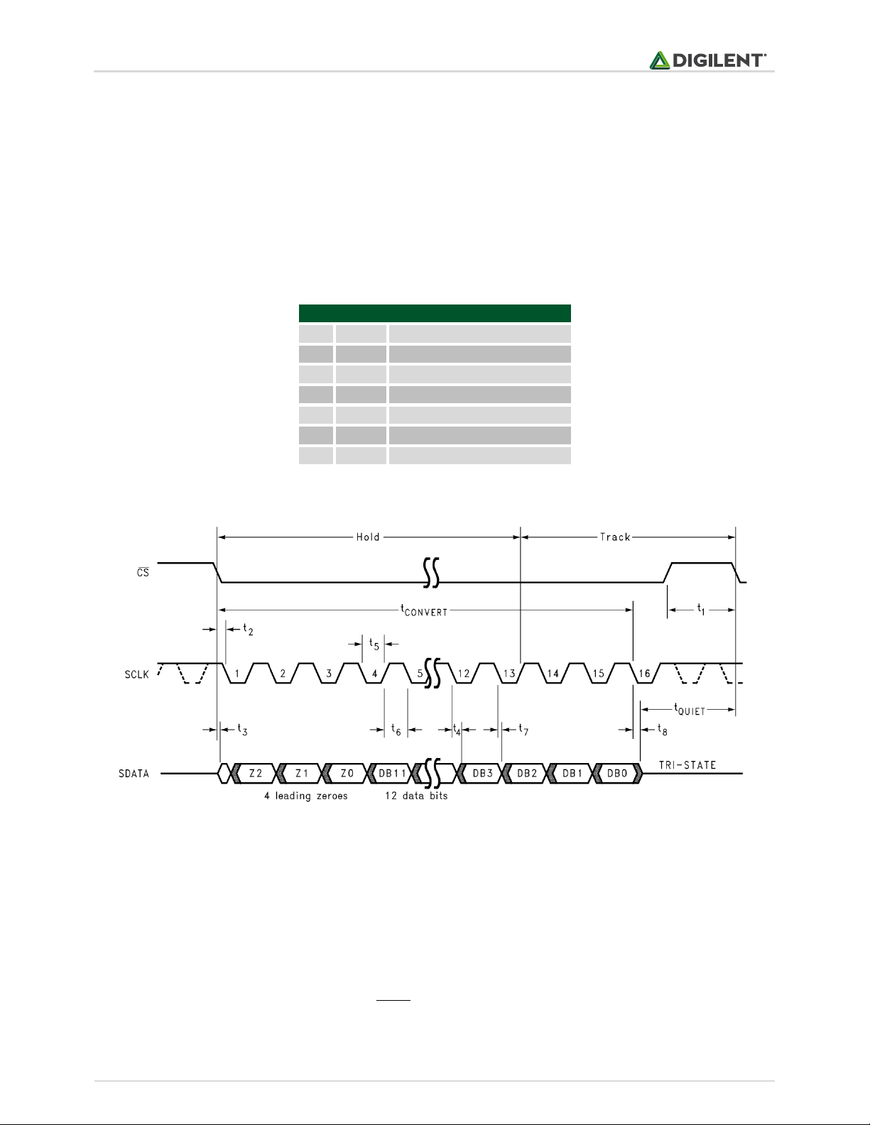
2 Interfacing with the Pmod
The PmodISNS20 communicates with the host board via the SPI protocol. The 12 bits of digital data are sent to the
system board in 16 clock cycles with the most significant bit first. For the ADC7476, each bit is shifted out on each
falling edge of the serial clock line after the chip select line is brought low with the first four bits as leading zeroes
and the remaining 12 bits representing the 12 bits of data. The datasheet for the ADC7476 recommends that for
faster microcontrollers or DSPs, the serial clock line is first brought to a high state before being brought low after
the fall of the chip select line to ensure that the first bit is valid.
Table 1. Pinout description table.
Figure 1. PmodISNS20 timing diagram.
The PmodISNS20 uses three wires to communicate with the host board. The wires used are Chip Select (CS), Serial
Clock (CLK), and Data Out (DO) – also known as MISO. At 0.0 Amps, the ADC will return over SPI a value of 2048. At
full negative current, a value of 0 will be returned, and likewise at full positive current a value of 4095 will be
returned. Knowing this we can derive the equation needed in order to convert this signal into useful information.

PmodISNS20™ Reference Manual
Copyright Digilent, Inc. All rights reserved.
Other product and company names mentioned may be trademarks of their respective owners.
Page 3 of 3
Rate
JP1
JP2
120 Hz
Enabled
Enabled
120 Hz
Enabled
Disabled
20 kHz
Disabled
Enabled
80 kHz
Disabled
Disabled
The scaling value at the beginning of the equation was derived using the provided sensitivity of 66mV/A off of the
ACS722 datasheet. Note that the provided sensitivity is based on a reference voltage of 3.3V to the sensor and our
design provides a regulated 3.0V for a cleaner signal, so some more correction may be needed if absolute accuracy
is needed.
Table 2 below shows how to configure the sampling rate frequency. The current sensing chip allows either 20 kHz
or 80 kHz sampling rate which is configured with Jumper 2. Enabling Jumper 1 turns on an analog filter to bring it
down to 120 Hz. The lower frequency is useful to keep noise down on <120 Hz AC circuit applications, such as
reading from mains power.
Table 2. Sample rate frequency configuration.
In order to read the amperage flowing through the ISNS20, the power source will need to be wired in series
through the green terminal block, noting proper polarity indicated by the silkscreen on the PCB. When using the
ISNS20 for measuring Alternating Current (such as from mains), absolute care should be taken. Improper use of the
ISNS20 on mains power can result in fire, injury, and even death – extreme caution should be taken.
Any external power applied to the PmodISNS20 must be within 3.0V and 3.6V; however, it is recommended that
Pmod is operated at 3.3V.
3 Physical Dimensions
The pins on the pin header are spaced 100 mil apart. The PCB is 1.3 inches long on the sides parallel to the pins on
the pin header and 0.8 inches long on the sides perpendicular to the pin header.
 Loading...