

Page 1
1300 Henley Court
Pullman, WA 99163
509.334.6306
www.digilentinc.com
PmodGPS™ Reference Manual
Revised April 12, 2016
This manual applies to the PmodGPS rev. A
DOC#: 502-237
Copyright Digilent, Inc. All rights reserved.
Other product and company names mentioned may be trademarks of their respective owners.
Page 1 of 6
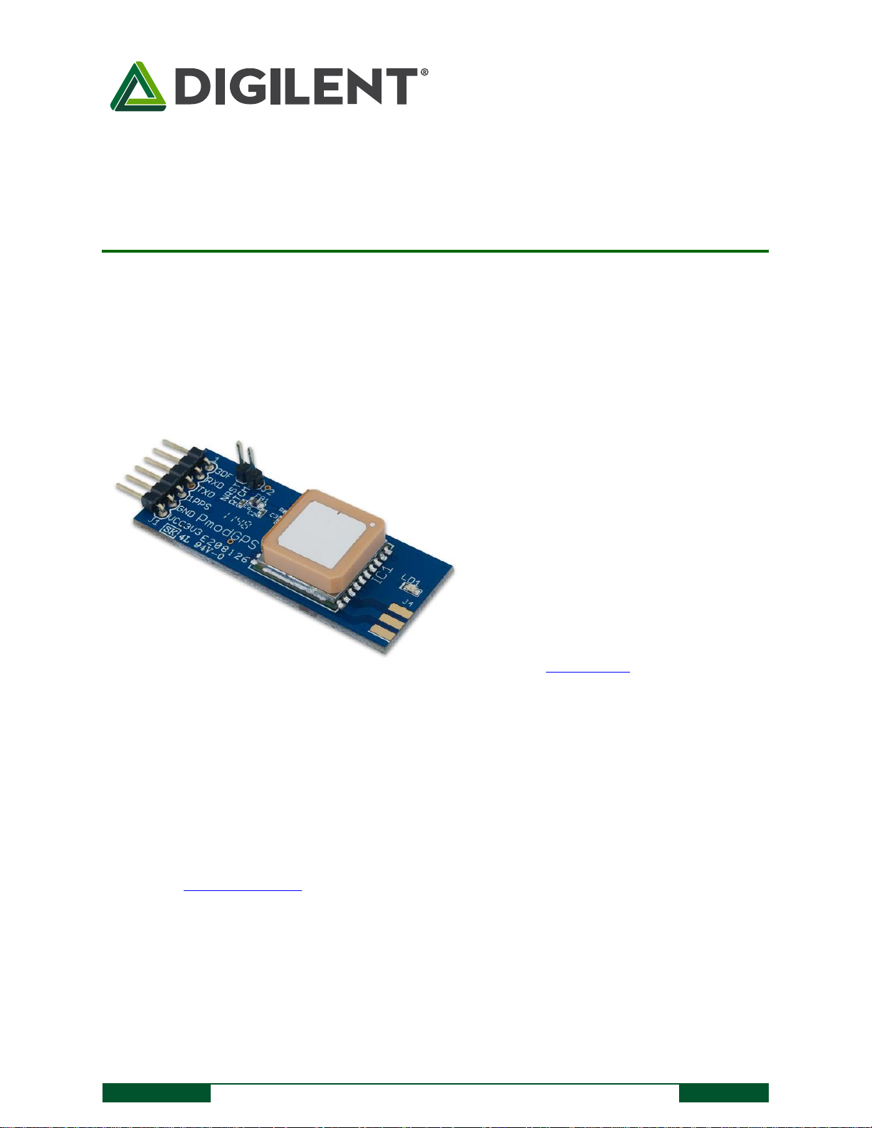
The PmodGPS.
Ultra-sensitive GPS module (-165 dBm)
Add 3m 2D satellite positioning
accuracy to any embedded system
Low power consumption
Up to 10Hz update rate
NMEA (default) and RTCM protocols
available
Small PCB size for flexible designs 2.0 in
× 0.8 in (5.0 cm × 2.0 cm)
6-pin Pmod port with UART interface
Library and example code available
in resource center
Features include:
Overview
The PmodGPS can add satellite positioning accuracy to any embedded system. The PmodGPS features a GlobalTop
FGPMMOPA6H GPS antenna module that utilizes the MediaTek GPS MT3329.
1 Functional Description
The PmodGPS uses a standard 6-pin port and communicates via a 2-wire Universal Asynchronous
Receiver/Transmitter (UART.) The PmodGPS also has a 2-pin port for control of the NRST pin to the module and the
Radio Technical Commission for Maritime services, or RTCM pin for Differential Global Positioning System (DGPS)
data using RTCM protocols.
Note: The PmodGPS arrives with the RTCM feature inactive, to enable RTCM capabilities users should contact
GlobalTop at: www.gtop-tech.com.
Page 2

PmodGPS™ Reference Manual
Copyright Digilent, Inc. All rights reserved.
Other product and company names mentioned may be trademarks of their respective owners.
Page 2 of 6
2 Interfacing with the Pmod
The PmodGPS uses UART protocol for data transmission and reception. The interface operates at a default baud
rate of 9.6 kBd, 8 data bits, no parity, and with single stop bits. However, users can change the baud rate to
predefined values that range from 4.8 kBd to 115.2 kBd.
The reset pin (NRST) on J2 allows normal operation in active low. If users toggle the NRST pin it will completely reset
the module. This reset performs similar to a power cycling of the device. The 1 PPS pin on J1 provides a one pulseper-second output synchronized with GPS time (see the timing diagram in Fig. 1).
The 3DF pin on J1 indicates the status of the user’s positional fix. When the module has a constant fix (2D or 3D)
this pin stays low, if the module is unable to get a fix then the pin will toggle every second. (See Fig. 2) LD1 also
follows this same behavior pattern in order to give the user a visual representation.
Figure 1. 1PPS Pin Timing Diagram.
Figure 2. 3DF Pin output without a fix.
The PmodGPS also comes equipped with a coin cell retainer for a 12.5 mm coin cell battery. Users can significantly
reduce the amount of time that it takes to acquire the first positional fix by installing a 3V coin cell battery. With the
battery installed the module can also perform a hot start or a warm start instead of cold starting where users have
to supply power to the VCC.
Note: The ground square solder pad of the coin cell retainer may develop an oxide build up that will keep the battery
from making a good connection. Users should simply scuff up the square solder pad inside J3 to remove any buildup.
Oxide buildup may also occur if there has not been a battery in the retainer for a while.
A cold start takes one or two minutes while outside in good conditions, and can take several minutes more if
conditions are worse or the module is indoors. A hot start takes three to five seconds and a warm start varies
depending on how long the module has sat unpowered. Users can hot start the PmodGPS only if it has acquired a
fix within approximately the last two hours and with accessible backup power (coin cell battery) connected to the
coin cell retainer. A warm start occurs when the battery is connected but the module has been without power for
more than two hours.
Users may utilize an external antenna at their discretion by installing a Linx Technologies Inc. CONSMA 003.062
module on header J4. The antenna can speed up acquisition of GPS signal in some conditions, especially if the
antenna is outdoors and the module is indoors.
Page 3
PmodGPS™ Reference Manual
Copyright Digilent, Inc. All rights reserved.
Other product and company names mentioned may be trademarks of their respective owners.
Page 3 of 6
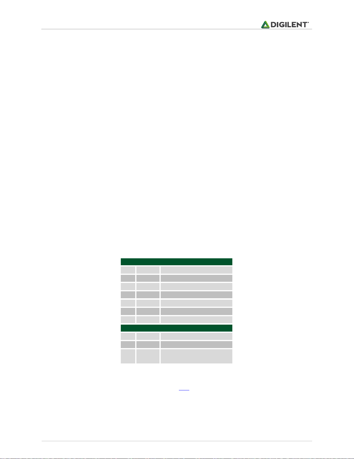
Connector J1
Pin
Signal
Description
1
3DF
3D-Fix Indicator
2
RX
Receive
3
TX
Transmit
4
1PPS
1 Pulse Per Second
5
GND
Power Supply Ground
6
VCC
Power Supply (3.3v)
Connector J2
Pin
Signal
Description
1
~RST
Reset (active low)
2
RTCM
DGPS data pin (contact
GlobalTop for use)
The PmodGPS uses sentences based on National Marine Electronics Association (NMEA) protocols for data output.
Each NMEA message begins with a ($) dollar sign. The next five characters are the talker ID and the arrival alarm.
The PmodGPS talker ID is “GP” and the arrival alarm is the specific sentence output descriptor. Individual comma
separated data fields follow these five characters. After the data fields there is an asterisk followed by a checksum.
Each sentence should end with <CR><LF>. For example output sentences refer to tables two through six at the end
of this manual.
User may configure some of the PmodGPS characteristics by writing command packets to the module. However,
these functions are more advanced and not all of the command packets are openly distributed. Users may change
the baud rate to 38.4kBd (minimum baud for 10Hz data acquisition) by issuing the following command over the
UART:
“$PMTK251,38400*27<CR><LF>”
The “*27” corresponds to a checksum, if users want to substitute a different baud rate, then they must calculate a
new checksum using GlobalTop’s Checksum Tool. The command for changing the data acquisition from 1Hz to 10Hz
is:
“$PMTK226,3,30*4<CR><LF>”
The same checksum process for changing the baud rate applies to this change too. Contact GlobalTop for more
information on the individual command packets, their complete command list, or see their FAQ for how to change
the baud rate.
Any external power applied to the PmodGPS must be within 2.7V and 5.25V; however, it is recommended that
Pmod is operated at 3.3V.
Table 1. Interface connector signal descriptions.
Note: Refer to the GlobalTop FGPMMOPA6H datasheet at here for more information on the GPS module interface.
Page 4
PmodGPS™ Reference Manual
Copyright Digilent, Inc. All rights reserved.
Other product and company names mentioned may be trademarks of their respective owners.
Page 4 of 6
Example
Description
$GPGGA
Message ID
064951.000
UTC Time
(hhmmss.sss)
2307.1256
Latitude
(ddmm.mmmm)
N
N/S indicator
12016.4438
Longitude
(dddmm.mmmm)
E
E/W indicator
1
Position Fix
Indicator
8
Satellites used
0.95
HDOP
39.9
MSL Altitude
M
Units
17.8
Geoidal Separation
M
Units
Age of Diff. Corr.
*65
Checksum
<CR><LF>
End of message
indicator
Example
Description
$GPGSA
Message ID
A
Mode1 (see
GlobalTop manual)
3
Mode2 (see
GlobalTop manual)
29
Satellite used (CH1)
21
Satellite used (CH2)
….
Satellite Used
(Ch12)
2.32
PDOP
0.95
HDOP
2.11
VDOP
*00
Checksum
<CR><LF>
End of message
indicator
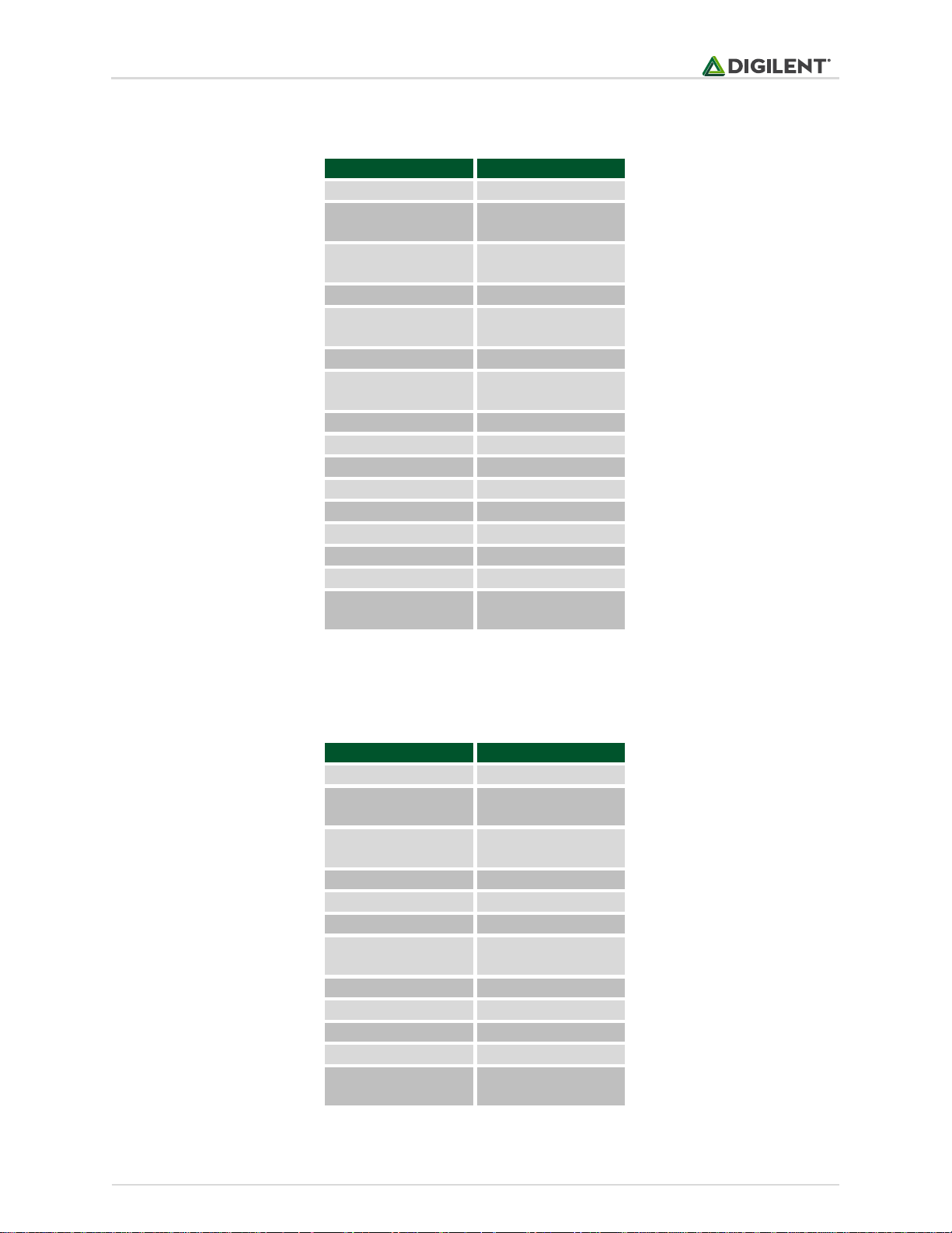
3 Output Sentences
Table 2. GGA.
$GPGGA,064951.000,2307.1256,N,12016.4438,E,1,8,0.95,39.9,M,17.8,M,,*65<CR><LF>
Table 3. GSA.
Page 5

PmodGPS™ Reference Manual
Copyright Digilent, Inc. All rights reserved.
Other product and company names mentioned may be trademarks of their respective owners.
Page 5 of 6
Example
Description
$GPGSV
Message ID
3
Number of
Messages
1
Message Number
09
Satellites in View
29
Satellite ID (CH1)
36
Elevation (CH1)
029
Azimuth (CH1)
42
SNR (C/No)
….
15
Satellite ID CH(4)
21
Elevation (CH4)
321
Azimuth (CH4)
39
SNR (C/No)
*7D
Checksum
<CR><LF>
End of message
indicator
Example
Description
$GPRMC
Message ID
064951.000
UTC Time (hhmmss.sss)
A
Status (A = data valid)
2307.1256
Latitude (ddmm.mmmm)
N
N/S indicator
12016.4438
Longitude (dddmm.mmmm)
E
E/W indicator
0.03
Speed over ground (knots)
165.48
Course over ground (degrees)
260406
Date (ddmmyy)
3.05
Magnetic Variation (degrees)
W
E/W indicator
A
Mode (see GlobalTop
manual)
*55
Checksum
<CR><LF>
End of message indicator
$GPGSA,A,3,29,21,26,15,18,09,06,10,,,,, 2.32,0.95,2.11*00<CR><LF>
Table 4. GSV.
$GPGSV,3,1,09,29,36,029,42,21,46,314,43, 26,44,020,43,15,21,321,39*7D<CR><LF>
$GPRMC,064951.000,A,2307.1256,N,12016.4438,E,0.03,165.48,260406,3.05,W,A*55<CR><LF>
Table 5. RMC.
Page 6

PmodGPS™ Reference Manual
Copyright Digilent, Inc. All rights reserved.
Other product and company names mentioned may be trademarks of their respective owners.
Page 6 of 6
Example
Description
$GPVTG
Message ID
165.48
Course (degrees)
T
Reference (true or false)
Course (degrees)
M
Reference (Magnetic)
0.03
Speed
N
Units (N = knots)
0.06
Speed
K
Units (K = km/hr)
A
Mode (see GlobalTop
manual)
*37
Checksum
<CR><LF>
End of message indicator
Table 6. VTG.
$GPVTG,165.48,T,,M,0.03,N,0.06,K,A*37<CR><LF>
4 Physical Dimensions
The pins on the pin header are spaced 100 mil apart. The PCB is 2.0 inches long on the sides parallel to the pins on
the pin header and 0.8 inches long on the sides perpendicular to the pin header.
Page 7

Mouser Electronics
Authorized Distributor
Click to View Pricing, Inventory, Delivery & Lifecycle Information:
Digilent:
410-237P 410-237
 Loading...