

Page 1
1300 Henley Court
Pullman, WA 99163
509.334.6306
www.digilentinc.com
PmodAMP2™ Reference Manual
Revised April 15, 2016
This manual applies to the PmodAMP2 rev. A
DOC#: 502-233
Copyright Digilent, Inc. All rights reserved.
Other product and company names mentioned may be trademarks of their respective owners.
Page 1 of 2
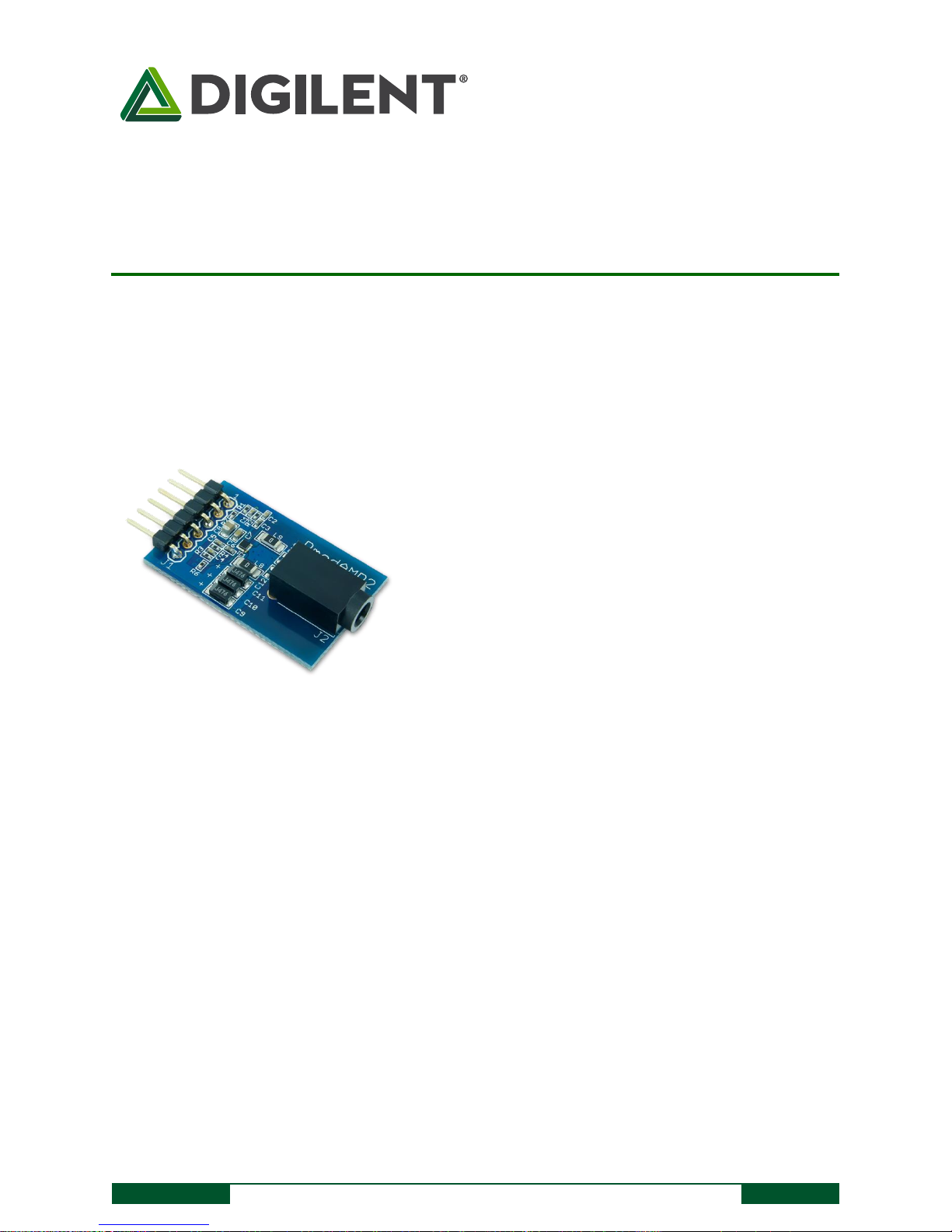
The PmodAMP2.
Filterless, high efficiency audio amplifier
Monophonic audio output
Standard 1/8“ (0.32 cm) mono speaker jack
Micropower shutdown mode
Pop–and-click suppression
Digital gain select
Small PCB size for flexible design at 1.25” × 0.8“ (3.2 cm
× 2.0 cm)
6-pin Pmod port with GPIO interface
Follows Digilent Pmod Interface Specification Type 1
Features include:
Overview
The Digilent PmodAMP2 amplifies low power audio signals to drive a monophonic output. This module offers a
digital gain select to allow output at a 6 or 12 dB gain with pop-and-click suppression.
1 Functional Description
The PmodAMP2 utilizes Analog Devices SSM2377 Mono Class-D audio amplifier. This module is designed to accept
an analog voltage signal as the incoming audio input, although a pulse-width modulated signal can also be easy
accepted after it passes through the reconstruction filter. A Σ-Δ modulator internal to the SSM2377 nicely
smoothes out the incoming analog signal to get a clean audio output signal.
2 Interfacing with the Pmod
The PmodAMP2 communicates with the host board via the GPIO protocol. What this entails for us is that there is
not a timing protocol that we need to follow. Rather, as long as your incoming digital data has a sample rate of at
least 16 kHz, the amplifier will be able to nicely handle the incoming data. Alternatively, an analog signal can be
provided and will also result in a corresponding sound output.
Page 2
PmodAMP2™ Reference Manual
Copyright Digilent, Inc. All rights reserved.
Other product and company names mentioned may be trademarks of their respective owners.
Page 2 of 2
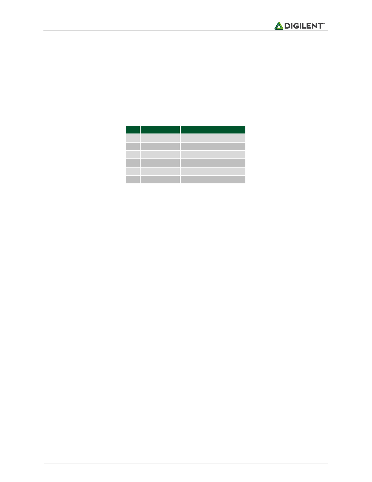
Pin
Signal
Description
1
AIN
Audio Input
2
GAIN
Gain Selection
3
NC
Not Connected
4
~SHUTDOWN
Active Low Shutdown
5
GND
Power Supply Ground
6
VCC
Power Supply (3.3V/5V)
A gain selection pin and active-low shutdown pins are also available for use. When the gain pin is driven high there
is a 6 dB gain applied to the incoming audio signals and a 12 dB gain applied to audio signals when the pin is driven
low.
The shutdown pin can be driven to a logic low level to place the SSM2377 into a very low power state with a
shutdown current of only 100 nA placing very little strain on the power source. The Pmod can be brought back into
normal operation mode by bringing the shutdown pin back to a logic high level for a maximum speaker output of
2.5W.
Table 1. Connector J1: Pin descriptions as labeled on the Pmod.
Any external power applied to the PmodAMP2 must be within 2.5V and 5.5V; however, it is recommended that
Pmod is operated at 3.3V.
3 Physical Dimensions
The pins on the pin header are spaced 100 mil apart. The PCB is 1.25 inches long on the sides parallel to the pins on
the pin header and 0.8 inches long on the sides perpendicular to the pin header.
Page 3

Mouser Electronics
Authorized Distributor
Click to View Pricing, Inventory, Delivery & Lifecycle Information:
Digilent:
410-233P-KIT 410-233
 Loading...