

Page 1
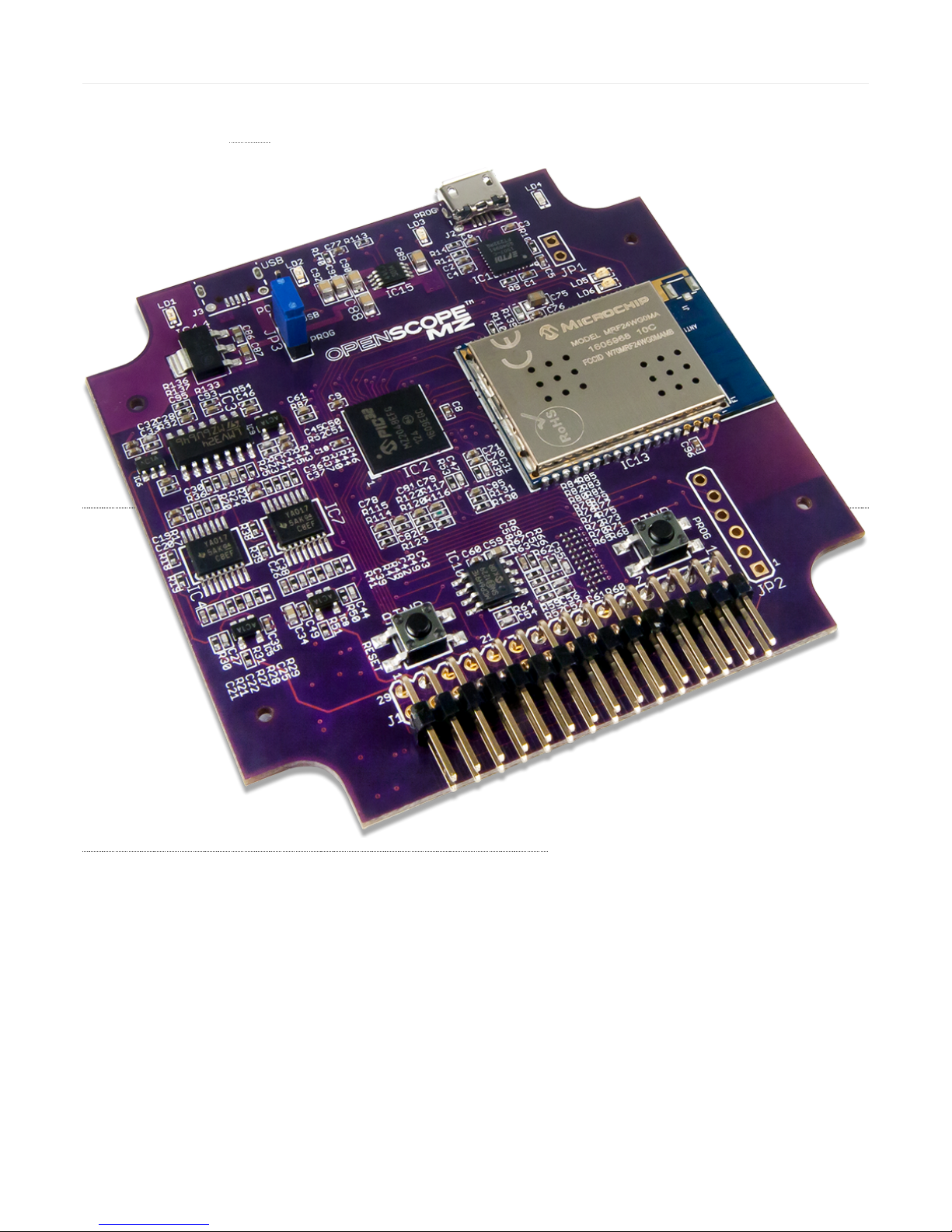
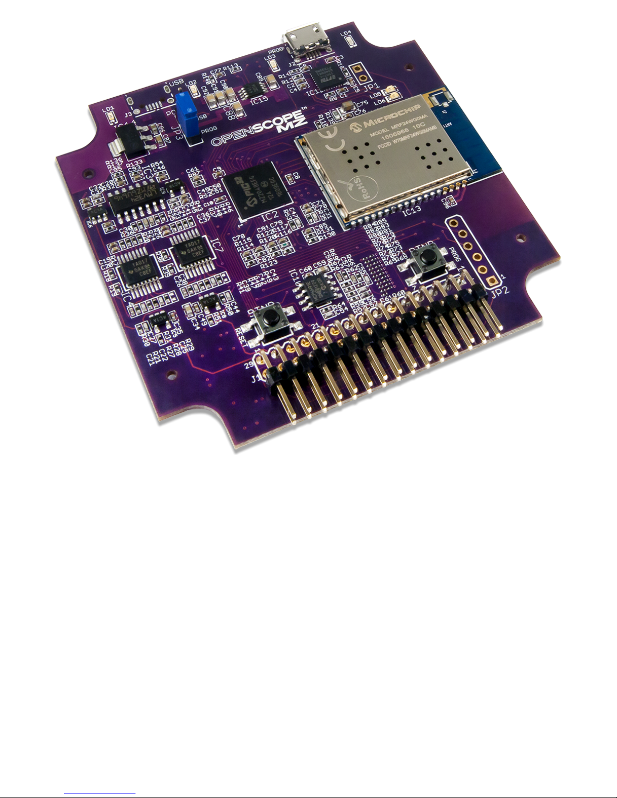
OpenScope MZ is an open source, multi-function, electronic instrumentation device that can be controlled using a computer or mobile device to acquire, analyze,
visualize, and generate signals from circuits, sensors, and other electronic devices. OpenScope MZ m akes it easy to generate analog and digital signals using the power
supply, function generator and GPIO () and measure and visualize analog and d igital signals using the oscilloscope and logic analyzer. Develop and debug circuits
faster by generating stimuli and visualizing the response using OpenScope MZ.
(https://reference.digilentinc.com/_m edia/reference/instrumentation/openscope-mz/openscope_mz_1.png)
OpenScope MZ Reference Manual
Page 2
Page 3
Page 4
Page 5
Page 6

Page 7

Connectivity
WiFi (802.11g)
USB 2.0 (High Speed Required)
Oscilloscope
2 Channels
12-bit resolution per channel
6.25 MS/s () sample rate
Flat bandwidth up to 1 MHz () at ±0.5dB
2 MHz () of bandwidth at -3dB
1 MΩ of input impedance
±20 V input voltage range
Features
Page 8

Maximum buffer size of 32640 samples per channel
Arbitrary Waveform G enerator
Sine, triangle, sawtooth, square and DC outputs
10-bit resolution
1 Hz () to 1 M Hz () frequency
3 V pk2pk o utput with ±1.5 V offset
10 mA output current
25000 sample buffer size
Logic Analyzer and GPIO ()
10 Channels multiplexed between the Logic Analyzer and as general purpose IO
3.3V CM OS logic for both the Logic Analyzer and GPIO ()
7 mA source and 12 mA sink when used as GPIO ()
Logic Analyzer has a sample rate of 10 MS/s ()
Maximum buffer size of 32640 samples per channel for the Logic Analyzer
Power Supply
2 Channels
±4 V output voltage
50 mA per channel
Other features
Two external triggers
USB pow ered device
4 user LEDs
PIC32MZ2048EFG124 microcontroller
(https://reference.digilentinc.com/_d etail/reference/instrumentation/openscope-mz/openscope_mz_hardware_block_diagram.png?id=reference%3Ainstrumentation%3Aopenscopemz%3Areference-manual)
(https://reference.digilentinc.com/_d etail/reference/instrumentation/openscope-mz/pinout_diagram.png?id=reference%3Ainstrumentation%3Aopenscope-mz%3Areference-manual)
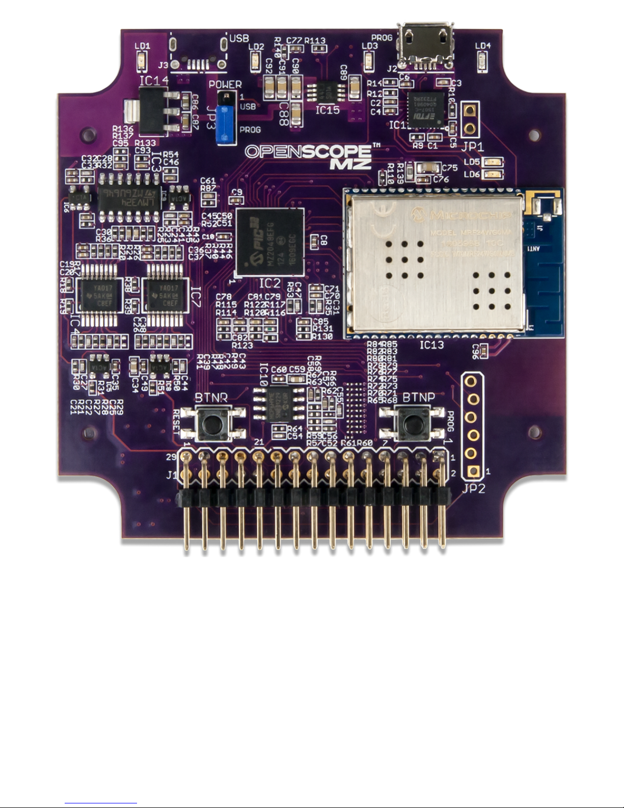
OpenScope MZ J1 Header Pinout
Top Row Bottom Row
1 D8 (8) 2 UART_RX/PWM2 (P5)
Page 9

3 D7 (7) 4 SPI_CS ()/UART_RTS/PWM1 (P4)
5 D6 (6) 6 SPI_CLK/UART_CTS (P3)
7 D5 (5) 8 SDI/SDO/UART_TX (P2)
9 D4 (4) 10 SDI/SD O (P1)
11 D3 (3) 12 INT ()/CLK2 (C2)
13 D2 (2) 14 DO10 (10)
15 D1 (1) 16 DO9 (9)
17 Trigger Input (T1) 18 Trigger Output (T0)
19 GND () (↓) 20 GND () (↓)
21 AWG1 (W1) 22 INT ()/CLK1 (C1)
23 DC Output 1 (V1) 24 DC Output 2 (V2)
25 GND () (↓) 26 GND () (↓)
27 AI2+/OSC2 (2+) 28 GND ()/AI2- (2-)
29 AI1+/OSC1 (1+) 30 GND ()/AI1- (1-)
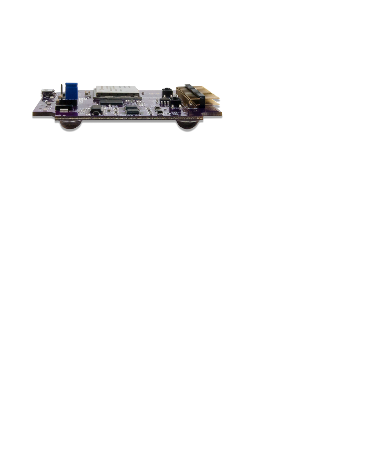
(https://reference.digilentinc.com/_d etail/reference/instrumentation/openscope-mz/openscopemz_walk_around.png?id=reference%3Ainstrumentation%3Aopenscopemz%3Areference-manual)
OpenScope MZ uses the ADC () on the PIC32MZ to create a 2 channel oscilloscope w ith 12-bits of resolution per channel. Each channel has a pair of analog inputs
with a PWM output to facilitate the interleaving of the two inputs, one PWM to handle the input offset voltages, and one DMA channel at the second highest priority
to transfer the measured data.
Walk Around the Board
Oscilloscope
Page 10

(https://reference.digilentinc.com/_d etail/reference/instrumentation/openscope-mz/analog_input_schematic.png?id=reference%3Ainstrumentation%3Aopenscope-mz%3Areferencemanual)
To ensure that the ADC () performs accurately, a 3 V reference with feedback must be assumed to be accurate w ith 0.1% resistors and 10% capacitors.
(https://reference.digilentinc.com/_d etail/reference/instrumentation/openscope-mz/3v_ref_for_adc.png?id=reference%3Ainstrumentation%3Aopenscope-mz%3Areference-manual)
The oscilloscope has the follow ing features:
2 Channels
12 bits of resolution per channel
6.25 MS/s () per channel
2 MHz () bandwidth at -3 dB
Input impedance of 1 M Ω
Input voltage range of ±20 V with protection up to ±40 V
Maximum Buffer Size of 32640 samples per channel
Reduced from a maximum size of 32766 samples to account for ADC () w arm-up and pre-trigger data, various delay timer overrun sources, and a 4
byte reduction to prevent large DM A stalls when the maximum destination block size is used.
The OpenScope MZ has a single channel 10 MS/s () 10-bit function generator. An R2R resistor ladder w ith 1% resistors is used in place of a DAC (). Due to the
nature of resistor ladders, it is possible to have a missing code for steps larger than 3 mV or encounter propagation delays, most notably w hen switching between the
values of 0x1FF and 0x200. The channel uses 10 IO pins on the PIC32MZ to generate the output through the resistor ladder and a DMA channel that is shared w ith
the Logic Analyzer at the highest priority level to transfer data and a PWM output to control the offset voltage level.
Function Generator
Page 11

(https://reference.digilentinc.com/_d etail/reference/instrumentation/openscope-mz/function_generator.png?id=reference%3Ainstrumentation%3Aopenscope-mz%3Areferencemanual)
(https://reference.digilentinc.com/_d etail/reference/instrumentation/openscope-mz/transm ission_delay.png?id=reference%3Ainstrumentation%3Aopenscope-mz%3Areferencemanual)
Digilent's WaveFormsLive (https://reference.digilentinc.com/reference/software/waveforms-live/start) supports a calibration option for the function generator where each
voltage cod e is applied and then read via the feedback network; the 1000 best codes that most closely match the ideal values (i.e. every 3 mV) are saved in a lookup
table for future use by the function generator.
(https://reference.digilentinc.com/_d etail/reference/instrumentation/openscope-mz/function_generator_feedback.png?id=reference%3Ainstrumentation%3Aopenscopemz%3Areference-manual)
The function generator supports:
Sine, triangle, sawtooth, square and DC outputs
Page 12

10-bit resolution
1 Hz () to 1 M Hz () frequency
3 V pk2pk o utput with ±1.5 V offset
20 mA output current
25000 sample buffer size
The OpenScope MZ has 10 user IO pins that are shared between the Logic Analyzer and as digital input/output pins. A DMA channel shared with the AWG at the
highest priority level is used to transfer data received by the PIC32MZ.
(https://reference.digilentinc.com/_d etail/reference/instrumentation/openscope-mz/io_ pins.png?id=reference%3Ainstrumentation%3Aopenscope-mz%3Areference-manual)
10 Channels multiplexed between the Logic Analyzer and as general purpose IO
3.3V CM OS logic
7 mA source and 12 mA sink when used as GPIO ()
Logic Analyzer has a sample rate of 10 MS/s ()
Maximum buffer size of 32640 samples per channel for the logic analyzer
Pins DIO0-DIO3 are 5V tolerant, pins DIO4-DIO9 are not 5V tolerant
OpenScope MZ has two DC outputs that are driven by their own PWM output w ith a single PWM line for the DC offset. A gain circuit is implmented on the
OpenScope MZ to provide a voltage range of -4 V to 4 V for each channel. A feedback circuit is also present to allow for calibration of the DC output.
(https://reference.digilentinc.com/_d etail/reference/instrumentation/openscope-mz/dc_output_m ain.png?id=reference%3Ainstrumentation%3Aopenscope-mz%3Areference-manual)
Digital I/O
DC Power Supplies
Page 13

(https://reference.digilentinc.com/_d etail/reference/instrumentation/openscope-mz/dc_output_feedback.png?id=reference%3Ainstrumentation%3Aopenscope-mz%3Areferencemanual)
2 channels
±4 V
50 mA per channel
A block diagram of how the OpenScope MZ communicates with the host is provided below:
(https://reference.digilentinc.com/_d etail/reference/instrumentation/openscope-mz/user_interface_communications.png?id=reference%3Ainstrumentation%3Aopenscopemz%3Areference-manual)
OpenScope MZ uses an FTdI FT232RQ U SB/Serial converter to handle the flow control between a host computer and a connected OpenScope MZ. The host
computer will need a U SB 2.0 High Speed (or better) port to allow the OpenScope MZ to run at 1.25 M Baud (139 kB/s) and to negotiate 500 mA on the USB bus.
Users may interact with the OpenScope MZ via a terminal in either Menu Mode or JSON Mod e. A pair of DMA channels at the lowest priority are d edicated to the
UART. If any other DMA channels stall out the UART DM A, all communication with the host will cease.
The OpenScope MZ uses a MRF24WG0MA WiFi chip to enable w ireless communication with a browser based UI, WaveFormsLive
(https://reference.digilentinc.com/reference/software/waveforms-live/start) (WFL). The OpenScope M Z itself implements a simple HTTP Server that stores static web
content on a μSD card and supports dynamic content implemented in the code through the Digilent deIP™ Network Stack. More information about WFL and the
Digilent Agent (https://reference.digilentinc.com/reference/software/digilent-agent/start) can be found on the OpenScope MZ Resource Center
(https://reference.digilentinc.com/reference/instrumentation/ openscope-mz/start).
8 out of 9 timers available on the PIC32MZ are utilized for the OpenScope MZ to trigger the ADCs, DMA transfers, PWM outputs, and trigger delays. Two timers
are dedicated to the ADC () channels, two are ded icated to the DC outputs, one for the DC offset, one for the function generator and logic analyzer, one for an
external trigger, and one for the hardware protocol.
Communication with the host
UART Interface
WiFi
Timers
Triggers
Page 14

The PIC32MZ triggers are used to initiate and control all of the DMA transfers in the OpenScope MZ. When a trigger is enabled, a data acquisition will run
continuously before the trigger event because it is not know n when the trigger event will occur. Data acquisition will also continue to run until all post trigger data is
collected. Due to d ata acquisition size limitations, it is not possible to measure a point of interest that exists too far in advance prior to the trigger event. The reverse
for a point of interest too far after a trigger event is also true.
Supported triggers for the oscilloscope are:
Rising or Falling Edge triggers
Rise/Fall time w ith lower and upper threshold
By default WaveForm s Live sets the lower threshold 30 mV b elow the upper threshold
Supported triggers for the logic analyzer are:
Rising, Falling or either Edge triggers
Any of the 10 LA signal channels in any combination
Pattern matching of the LA signal channels is not supported
8 out of 8 D MA channels available on the PIC32MZ are used on the OpenScope MZ. Tw o channels are dedicated to UART, a pair of DMA channels are assigned
to each interleaved AD C () channel for a total of four channels, one channel is shared betw een the function generator and the logic analyzer and one dedicated to
hardware protocol communication. All DMA channels can be triggered on any interrupt event and do not require the use of an ISR.
DMA is used to transfer data without utilizing the CPU by working in parallel with the CPU and has to ability to access peripherals and non-cached memory at much
greater speeds. DMA cell transfers are serialized so care is taken in the OpenScope firmw are to ensure that multiple channels are not triggered above 10 MT/s to
prevent a high priority channel from stalling all other DM A channels.
9 PWM channels of the PIC32MZ are implemented on the OpenScope MZ. Tw o are used in the interleaving of the ADC () channels, three are used for offsets for
the AWG and both analog input channels, two are used for the DC outputs, and the remaining two used as offsets for the DC outputs.
The PWM outputs have 330 unique values ranging from 0 V to 3.3 V, w ith a step size of 10 mV. The internal clock runs at 100 M Hz (), providing a PWM frequency
of 303 kHz (). All of the analog designs on the OpenScope MZ are based on PWM values from 50 to 300 to allow some headroom for calibration.
The LEDs on the OpenScope MZ are used to indicate the current status of the OpenScope MZ hardw are as follow s:
Note: Firmware versions prior to 1.2.0 will not exhibit the LED () behavior described below.
Blue Off - Device is booting and not read y to use.
Blue Flashing - Device is booted and ready to use but Wifi is not connected.
Blue Solid - D evice is booted and ready to use and Wifi is connected.
The three other LEDs blink the last octet of the OpenScope MZ's IP Address.
Red Solid - Calibration or acquisition in progress.
All user LEDs Solid - An error has occurred. Reboot the OpenScope M Z.
When connected to a Wifi network the 3 user LEDs display the last octet of the OpenScope MZ's IP address by blinking the number of times corresponding
to that digit of the last octet in decimal. For example an OpenScope M Z with an IP address ending in '123' w ould blink LD1 once, LD2 tw ice and LD3 three
times.
DMA
PWM
Troubleshooting
LED Indicators
Subscribe to our Newsletter
 Loading...