

Page 1
iiggiilleenntt MMoodduullaarr IInntteerrffaaccee BBooaarrdd
eeffeerreennccee MMaannuuaal
evision: 3/11/05 215 E Main Suite D | Pullman, WA 99163
l
www.digilentinc.com
(509) 334 6306 Voice and Fax
verview
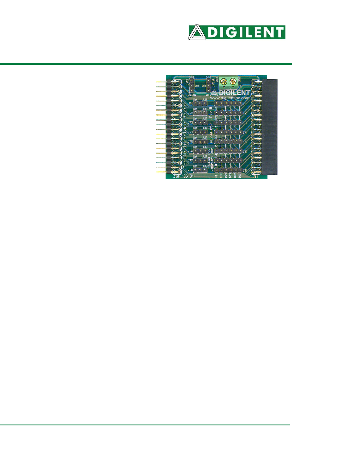
he Digilent Modular Interface Board (the MIB)
onnects outside devices to a Digilent system
oard.
he MIB can connect up to eight outside
evices (including the Digilent module and hridge boards) to system boards such as the
egasus or Spartan 3 boards.
he MIB is especially useful for robotics
rojects, where numerous I/O connections to a
igilent system board are necessary.
eatures include:
®
• eight 6-pin headers for connection to
module boards
• separate power selection for each 6-pin
header
• 40-pin header
• 40-pin socket
• flexible power routing
• test-point header functionality
• small form factor (2.20” x 2.20”).
unctional Description
he MIB is designed primarily for use with the
igilent line of 6-pin module boards, and
igilent system boards such as the Pegasus
nd Spartan 3.
he MIB plugs into a system board’s 40-pin
ocket. The MIB allows up to 32 user I/O
ignals, routed through eight 6-pin headers.
ach 6-pin header conveys four I/O signals,
ne power signal, and one ground signal.
he MIB can also be used as a test point
eader when needed.
MIB Power Routing
The MIB allows flexible power routing. Two
distinct voltages can be created using the
same MIB.
The power supply from external devices is
routed through two power buses, labeled “VA”
and “VB”.
The VA bus provides power from the attached
system board’s 3.3V or VU supply. The VB bus
provides power from the attached system
board’s VU supply or from an outside power
supply (via the 2-pin terminal block labeled “J9”
on the MIB).
Each set of signals is accessed via a 6-pin
header. These headers are labeled J1 through
J8. The power supply bus for each of these
headers is selected using a jumper shunt on
the associated jumper pins JP1 through JP8.
Power selection for each power bus is selected
using jumper shunts at JP9 (VA bus) and JP10
(VB bus). This allows for two distinct voltages
using the same MIB. External power is applied
through a screw terminal at J9.
oc: 502-057 page 1 of 2
Copyright Digilent, Inc. All rights reserved. Other product and company names mentioned may be trademarks of their respective owners.
Page 2

igilent MIB Reference Manual Digilent, Inc.
he following diagram shows how the MIB can
e configured to provide 3.3V from the VA bus
t header J1 and external power (VE, labeled
VCC” on J9) on the VB bus for header J2.
VUVU
VA VB
JP9
JP10
3.3V VE
JP1
JP2
JP3
JP4
JP5
JP6
JP7
JP8
J1
J2
J3
J4
J5
J6
J7
J8
VA VB
MIB Configuration
onnecting Devices to the MIB
igilent’s module boards are connected to the
IB using a Digilent 6-pin expansion cable.
hese cables are available in six and eighteen
ch versions.
or more information, see www.digilentinc.com.
MIB Pinout Table
The table below shows the pin assignments for
the expansion and 6-pin headers on the MIB.
Module
Header (J10)
To System
Board
38 J1 1 4
36 2 6
35 3 5
34 4 8
33 J2 1 7
32 2 10
31 3 9
30 4 12
29 J3 1 11
28 2 14
27 3 13
26 4 16
25 J4 1 15
24 2 18
23 3 17
22 4 20
21 J5 1 19
20 2 22
19 3 21
18 4 24
17 J6 1 23
16 2 26
15 3 25
14 4 28
13 J7 1 27
12 2 30
11 3 29
10 4 32
9 J8 1 31
8 2 34
7 3 33
5 4 35
* For all 6-pin headers, the number 5 pins on are
connected to ground and the number 6 pins are
Connectors Socket (J11)
To Peripheral
6-Pin Headers
connected to power.
Board
ww.digilentinc.com page 2 of 2
Copyright Digilent, Inc. All rights reserved. Other product and company names mentioned may be trademarks of their respective owners.
 Loading...