


USB-DIO96H
User's Guide
September 2019. Rev 13
High-drive Digital I/O
Hardware Revision 2
© Measurement Computing Corporation.

HM USB-DIO96H_R2.docx
Trademark and Copyright Information
Measurement Computing Corporation, InstaCal, Universal Library, and the Measurement Computing logo are
either trademarks or registered trademarks of Measurement Computing Corporation. Refer to the Copyrights &
Trademarks section on mccdaq.com/legal
for more information about Measurement Computing trademarks.
Other product and company names mentioned herein are trademarks or trade names of their respective
companies.
© 2019 Measurement Computing Corporation. All rights reserved. No part of this publication may be
reproduced, stored in a retrieval system, or transmitted, in any form by any means, electronic, mechanical, by
photocopying, recording, or otherwise without the prior written permission of Measurement Computing
Corporation.
Notice
Measurement Computing Corporation does not authorize any Measurement Computing Corporation product for
use in life support systems and/or devices without prior written consent from Measurement Computing
Corporation. Life support devices/systems are devices or systems that, a) are intended for surgical implantation
into the body, or b) support or sustain life and whose failure to perform can be reasonably expected to result in
injury. Measurement Computing Corporation products are not designed with the components required and are
not subject to the testing required to ensure a level of reliability suitable for the treatment and diagnosis of
people.

Table of Contents
Preface
About this User's Guide ....................................................................................................................... 4
What you will learn from this user's guide ......................................................................................................... 4
Conventions in this user's guide ......................................................................................................................... 4
Where to find more information ......................................................................................................................... 4
Chapter 1
Introducing the USB-DIO96H ............................................................................................................... 5
USB-DIO96H block diagram ............................................................................................................................. 6
Chapter 2
Installing the USB-DIO96H ................................................................................................................... 7
Unpacking........................................................................................................................................................... 7
Installing the software ........................................................................................................................................ 7
Connecting the external power supply ................................................................................................................ 7
Installing the hardware ....................................................................................................................................... 7
Chapter 3
Functional Details ................................................................................................................................. 9
Components ........................................................................................................................................................ 9
USB IN connector ............................................................................................................................................................. 9
External power connector ................................................................................................................................................. 9
Molex connector ..............................................................................................................................................................10
Power source jumper JP2 .................................................................................................................................................10
USB LED .........................................................................................................................................................................10
PWR LED ........................................................................................................................................................................11
User connectors................................................................................................................................................................11
Pull-up/pull-down DIP switches ......................................................................................................................................11
Signal connections ............................................................................................................................................ 11
Digital I/O (FIRSTPORTA Bit 0 to FOURTHPORTC Bit 7) .........................................................................................13
Counter input ...................................................................................................................................................................13
Power outputs ..................................................................................................................................................................13
Ground .............................................................................................................................................................................13
Mechanical drawings ........................................................................................................................................ 14
Chapter 4
Specifications ...................................................................................................................................... 15
Digital input/output........................................................................................................................................... 15
Power ................................................................................................................................................................ 16
Counter ............................................................................................................................................................. 16
Environmental .................................................................................................................................................. 17
USB specifications ........................................................................................................................................... 17
Data transfer rates ............................................................................................................................................. 17
Mechanical ....................................................................................................................................................... 17
Screw terminal connectors ................................................................................................................................ 17
Screw terminal pinout ......................................................................................................................................................18
Ribbon connectors ............................................................................................................................................ 19
P1 pinout ..........................................................................................................................................................................19
P2 pinout ..........................................................................................................................................................................20
P3 pinout ..........................................................................................................................................................................21
P4 pinout ..........................................................................................................................................................................22
Declaration of Conformity .................................................................................................................. 23
3
Preface
About this User's Guide
What you will learn from this user's guide
This user's guide describes the Measurement Computing USB-DIO96H data acquisition device and lists device
specifications.
This manual applies to revision 2 hardware and later
This manual applies to revision 2 of the USB-DIO96H hardware, which uses a 5 V power supply. Revision 1 of
the USB-DIO96H hardware has a 9 V power supply and daisy-chained hub. For information on revision 1
hardware, refer to www.mccdaq.com/pdfs/manuals/USB-DIO96H_R1.pdf.
Conventions in this user's guide
For more information
Text presented in a box signifies additional information and helpful hints related to the subject matter you are
reading.
Caution! Shaded caution statements present information to help you avoid injuring yourself and others,
damaging your hardware, or losing your data.
bold text Bold text is used for the names of objects on a screen, such as buttons, text boxes, and check boxes.
italic text Italic text is used for the names of manuals and help topic titles, and to emphasize a word or phrase.
Where to find more information
Additional information about the USB-DIO96H is available on our website at www.mccdaq.com. You can also
contact Measurement Computing Corporation by phone, fax, or email with specific questions.
Knowledgebase: kb.mccdaq.com
Tech support form: www.mccdaq.com/support/support_form.aspx
Email: techsupport@mccdaq.com
Phone: 508-946-5100 and follow the instructions for reaching Tech Support
4

Chapter 1
Introducing the USB-DIO96H
The USB-DIO96H is a USB 2.0 full-speed device that provides the following features:
96 bits of digital I/O lines in four independent port groups,
o Each group is divided into two 8-bit ports and two 4-bit ports, and is a discrete emulation of 82C55
mode zero operation
o Each port is software-selectable for either input or output
o Each digital port has associated DIP switches to drive the ports high or low during power up and reset
(pull-up or pull-down configuration.) All I/O bits are set to input mode on power up and reset.
High-drive TTL outputs that can source 24 mA and sink 64 mA
A 32-bit external event counter.
Screw terminals for signal I/O connections
50-pin mass termination connectors for OEM applications (remove enclosure to access mass termination
connectors)
Rugged metal enclosure that can mount on a DIN rail or on a bench. A USB cable is included.
The USB-DIO96H is fully compatible with both USB 1.1 and USB 2.0 ports. Revision G and later devices are
also compatible with USB 3.0 ports.
The USB-DIO96H is powered by an external +5 V regulated power supply that is shipped with the device.
A jumper-selectable Molex® connector is also available inside the case if you need an alternate power supply.
The cable for this connector is not included.
This manual applies to revision 2 hardware and later
This manual applies to revision 2 of the USB-DIO96H hardware, which uses a 5 V power supply. Revision 1 of
the USB-DIO96H hardware has a 9 V power supply and daisy-chained hub. For information on revision 1
hardware, refer to www.mccdaq.com/PDFs/specs/USB-DIO96H_R1-spec.pdf.
5

USB-DIO96H User's Guide Introducing the USB-DIO96H
USB-DIO96H block diagram
USB-DIO96H functions are illustrated in the block diagram shown here.
Figure 1. USB-DIO96H functional block diagram
6

Chapter 2
Installing the USB-DIO96H
Unpacking
As with any electronic device, you should take care while handling to avoid damage from static
electricity. Before removing the device from its packaging, ground yourself using a wrist strap or by simply
touching the computer chassis or other grounded object to eliminate any stored static charge.
Contact us immediately if any components are missing or damaged.
Installing the software
Refer to the MCC DAQ Quick Start and the USB-DIO96H product page on our website for information about
the available software.
Install the software before you install your device
The driver needed to run the USB-DIO96H is installed with the software. Therefore, you need to install the
software package you plan to use before you install the hardware.
Connecting the external power supply
Power to the USB-DIO96H is provided with the +5 V external power supply (PS-5V3AEPS). You must
connect the external power supply before connecting the USB cable to the USB-DIO96H and your computer.
To connect the power supply to the USB-DIO96H, connect the external power cord to the power connector
labeled
location of this connector.
The
+4.1 V or more than +5.6 V, the
POWER IN on the USB-DIO96H enclosure (P5 on the board). Refer to Figure 2 on page 9 for the
PWR LED lights up when +5 V power is supplied to the USB-DIO96H. If the voltage supply is less than
PWR LED does not turn on.
Installing the hardware
To connect the USB-DIO96H to your system, complete the following steps.
1. Turn your computer on.
2. Connect the USB cable to the USB connector labeled USB IN on the USB-DIO96H.
3. Connect the other end of the USB cable to a USB port on your computer or to an external USB hub that is
connected to your computer.
The
USB LED turns on. Refer to Figure 2 on page 9 for the location of the USB LED.
Caution! Do not disconnect the device from the USB bus while the USB LED is on and the computer is
communicating with the USB-DIO96H. You may lose data and/or your ability to communicate
with the USB-DIO96H.
If the USB LED turns off
If the USB LED turns on but then turns off, the computer has lost communication with the USB-DIO96H. To
restore communication, disconnect the USB cable from the computer, and then reconnect it. This should restore
communication, and the USB LED should turn back on.
7

USB-DIO96H User's Guide Installing the USB-DIO96H
If your system does not detect the USB-DIO96H
Perform the following procedure if a "
USB device not recognized" message appears when you connect the
USB-DIO96H:
1. Unplug the USB cable from the USB-DIO96H.
2. Unplug the external power cord from the
3. Plug the external power cord back into the
POWER IN connector on the enclosure.
POWER IN connector.
4. Plug the USB cable back into the USB-DIO96H.
Your system should now properly detect the USB-DIO96H hardware. Contact technical support if your system
still does not detect the USB-DIO96H.
8

1
USB IN connector
6
USB LED
2
POWER IN)
7
PWR
3
Molex connector (P6)
8
50-pin connectors (x4)
4
Power source jumper (J2)
9
Pull-up/down DIP switches (x4)
5
Ports 1 through 4
Functional Details
Components
These USB-DIO96H components are shown in Figure 2.
Chapter 3
External power connector (
Figure 2. USB-DIO96H components
LED
USB IN connector
The USB in connector is labeled USB IN on the enclosure and J1 on the board. This connector is a USB 2.0
full-speed input connector that you connect to the USB port on your computer (or USB hub connected to your
computer). This connector supports USB 1.1 and USB 2.0 devices.
Hardware revision G and later are also compatible with USB 3.0 ports. The board revision may be determined
from the part number label on the enclosure that states "193770X-01L", where X is the board revision.
External power connector
The USB-DIO96H has an external power connector labeled POWER IN on the enclosure and P5 on the board.
Connect the
at full load, the USB-DIO96H draws 2.7 A from the supply.
POWER IN connector to the supplied +5 V external power supply (PS-5V3AEPS). When running
9

USB-DIO96H User's Guide Functional Details
Pin 1
NC (no connect)
Pin 2
GND
Pin 3
GND
Pin 4
5V
Steady green
The USB-DIO96H is connected to a computer or external USB hub.
Continuous blink
Initial communication is established between the device and the computer, or data is being
transferred.
Molex connector
The internal Molex connector is labeled P6 on the board. Remove the device enclosure to access this connector.
Internal power connector pinout
Pin 1 (NC) of the Molex connector is directly to the left of the power source jumper (JP2).
Figure 3. Molex connector (P6) pin assignments
Power source jumper JP2
The power source jumper is labeled JP2 on the board. Use this jumper to configure the USB-DIO96H to use
either the external power connector (
POWER IN) or the Molex connector. Figure 4shows the jumper in each
configuration mode.
JP2 JP2
Power from external supply
(default position)
Figure 4. JP2 configuration modes
Power from internal
Molex connector
USB LED
The USB LED turns on to indicate the communication status of the USB-DIO96H. It uses up to 5 mA of current
and cannot be disabled. The table below explains the behavior of the
USB LED behavior
USB LED.
LED Behavior Indication
10

USB-DIO96H User's Guide Functional Details
PWR LED
The PWR LED turns on when external power is supplied. The USB-DIO96H incorporates an onboard voltage
supervisory circuit that monitors the external power supply and disconnects power from the rest of the board
components if the external power supply voltage is too high or too low. The
power is not supplied to board components under the following circumstances:
when the input power falls below +4.1 V
when the input power goes above +5.6 V
PWR LED does not turn on, and
User connectors
The USB-DIO96H has screw terminals for user connections. Refer to the Screw terminal pinout on page 12 for
terminal assignments. (There are also optional header connectors available for applications in which the
enclosure is not necessary.)
Pull-up/pull-down DIP switches
Use the on-board DIP switches labeled PORT 1 through PORT 4 to configure the pull-up/down configuration
for each port. Each set of DIP switches includes four switches labeled 1 to 4. Switch 1 controls PORTA, switch
2 controls PORTB, switch 3 controls PORTCL, and switch 4 controls PORTCH.
Figure 5 shows the DIP switches used to configure Port 1.
Figure 5. Pull-up/down switch configuration
All DIP switches are configured by default for pull-up (PU). To configure for pull-down, slide the switch to the
PD position.
Signal connections
The USB-DIO96H has four rows of screw terminals labeled Port 1 through Port 4 that provide the following
connections:
96 digital I/O lines (
One external event counter input (
Three VDD power outputs (
Four ground terminals (
Use 14 AWG to 30 AWG wire for your signal connections. Each screw terminal is identified with a label on the
board and on the underside of the enclosure lid. Refer to the Screw terminal pinout on page 12
name associated with each board label.
Caution! Keep the length of stripped wire at a minimum to avoid a short to the enclosure! When connecting
your field wiring to the screw terminals, use the strip gage on the terminal strip, or strip to 5.5 mm
to 7.0 mm (0.215 in. to 0.275 in.) long.
A0 to C7 for Port 1 through Port 4)
CTR)
5V)
GND)
for the signal
11
USB-DIO96H User's Guide Functional Details
Board label
Signal name
Board label
Signal name
A0
P1A0 (FIRSTPORTA Bit 0)
A0
P3A0 (THIRDPORTA Bit 0)
A1
P1A1 (FIRSTPORTA Bit 1)
A1
P3A1 (THIRDPORTA Bit 1)
A2
P1A2 (FIRSTPORTA Bit 2)
A2
P3A2 (THIRDPORTA Bit 2)
A3
P1A3 (FIRSTPORTA Bit 3)
A3
P3A3 (THIRDPORTA Bit 3)
A4
P1A4 (FIRSTPORTA Bit 4)
A4
P3A4 (THIRDPORTA Bit 4)
A5
P1A5 (FIRSTPORTA Bit 5)
A5
P3A5 (THIRDPORTA Bit 5)
A6
P1A6 (FIRSTPORTA Bit 6)
A6
P3A6 (THIRDPORTA Bit 6)
A7
P1A7 (FIRSTPORTA Bit 7)
A7
P3A7 (THIRDPORTA Bit 7)
B0
P1B0 (FIRSTPORTB Bit 0)
B0
P3B0 (THIRDPORTB Bit 0)
B1
P1B1 (FIRSTPORTB Bit 1)
B1
P3B1 (THIRDPORTB Bit 1)
B2
P1B2 (FIRSTPORTB Bit 2)
B2
P3B2 (THIRDPORTB Bit 2)
B3
P1B3 (FIRSTPORTB Bit 3)
B3
P3B3 (THIRDPORTB Bit 3)
B4
P1B4 (FIRSTPORTB Bit 4)
B4
P3B4 (THIRDPORTB Bit 4)
B5
P1B5 (FIRSTPORTB Bit 5)
B5
P3B5 (THIRDPORTB Bit 5)
B6
P1B6 (FIRSTPORTB Bit 6)
B6
P3B6 (THIRDPORTB Bit 6)
B7
P1B7 (FIRSTPORTB Bit 7)
B7
P3B7 (THIRDPORTB Bit 7)
C0
P1C0 (FIRSTPORTC Bit 0)
C0
P3C0 (THIRDPORTC Bit 0)
C1
P1C1 (FIRSTPORTC Bit 1)
C1
P3C1 (THIRDPORTC Bit 1)
C2
P1C2 (FIRSTPORTC Bit 2)
C2
P3C2 (THIRDPORTC Bit 2)
C3
P1C3 (FIRSTPORTC Bit 3)
C3
P3C3 (THIRDPORTC Bit 3)
C4
P1C4 (FIRSTPORTC Bit 4)
C4
P3C4 (THIRDPORTC Bit 4)
C5
P1C5 (FIRSTPORTC Bit 5)
C5
P3C5 (THIRDPORTC Bit 5)
C6
P1C6 (FIRSTPORTC Bit 6)
C6
P3C6 (THIRDPORTC Bit 6)
C7
P1C7 (FIRSTPORTC Bit 7)
C7
P3C7 (THIRDPORTC Bit 7)
5V
5V
5V
5V
GND
GND
GND
GND
A0
P2A0 (SECONDPORTA Bit 0)
A0
P4A0 (FOURTHPORTA Bit 0)
A1
P2A1 (SECONDPORTA Bit 1)
A1
P4A1 (FOURTHPORTA Bit 1)
A2
P2A2 (SECONDPORTA Bit 2)
A2
P4A2 (FOURTHPORTA Bit 2)
A3
P2A3 (SECONDPORTA Bit 3)
A3
P4A3 (FOURTHPORTA Bit 3)
A4
P2A4 (SECONDPORTA Bit 4)
A4
P4A4 (FOURTHPORTA Bit 4)
A5
P2A5 (SECONDPORTA Bit 5)
A5
P4A5 (FOURTHPORTA Bit 5)
A6
P2A6 (SECONDPORTA Bit 6)
A6
P4A6 (FOURTHPORTA Bit 6)
A7
P2A7 (SECONDPORTA Bit 7)
A7
P4A7 (FOURTHPORTA Bit 7)
B0
P2B0 (SECONDPORTB Bit 0)
B0
P4B0 (FOURTHPORTB Bit 0)
B1
P2B1 (SECONDPORTB Bit 1)
B1
P4B1 (FOURTHPORTB Bit 1)
B2
P2B2 (SECONDPORTB Bit 2)
B2
P4B2 (FOURTHPORTB Bit 2)
B3
P2B3 (SECONDPORTB Bit 3)
B3
P4B3 (FOURTHPORTB Bit 3)
B4
P2B4 (SECONDPORTB Bit 4)
B4
P4B4 (FOURTHPORTB Bit 4)
B5
P2B5 (SECONDPORTB Bit 5)
B5
P4B5 (FOURTHPORTB Bit 5)
B6
P2B6 (SECONDPORTB Bit 6)
B6
P4B6 (FOURTHPORTB Bit 6)
B7
P2B7 (SECONDPORTB Bit 7)
B7
P4B7 (FOURTHPORTB Bit 7)
C0
P2C0 (SECONDPORTC Bit 0)
C0
P4C0 (FOURTHPORTC Bit 0)
C1
P2C1 (SECONDPORTC Bit 1)
C1
P4C1 (FOURTHPORTC Bit 1)
C2
P2C2 (SECONDPORTC Bit 2)
C2
P4C2 (FOURTHPORTC Bit 2)
C3
P2C3 (SECONDPORTC Bit 3)
C3
P4C3 (FOURTHPORTC Bit 3)
C4
P2C4 (SECONDPORTC Bit 4)
C4
P4C4 (FOURTHPORTC Bit 4)
C5
P2C5 (SECONDPORTC Bit 5)
C5
P4C5 (FOURTHPORTC Bit 5)
C6
P2C6 (SECONDPORTC Bit 6)
C6
P4C6 (FOURTHPORTC Bit 6)
C7
P2C7 (SECONDPORTC Bit 7)
C7
P4C7 (FOURTHPORTC Bit 7)
CTR
CTR
5V
5V
GND
GND
GND
GND
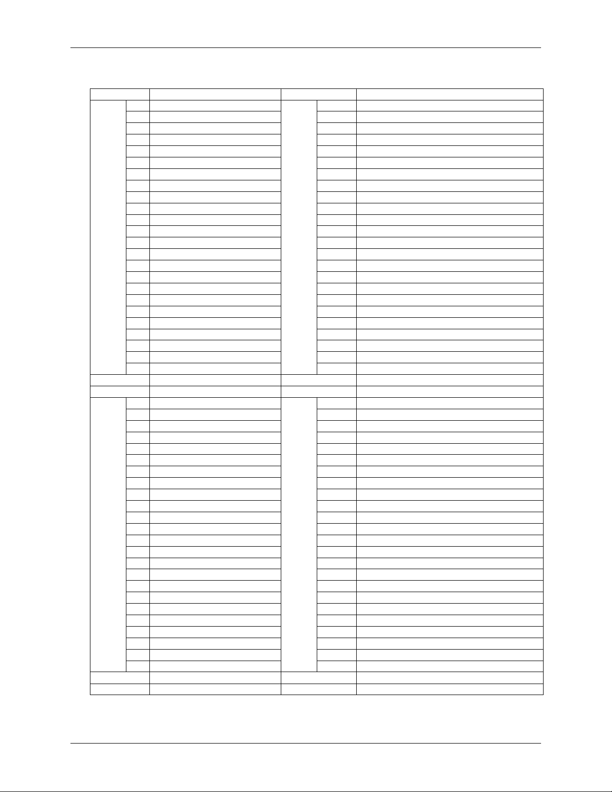
Screw terminal pinout
Port 1
Port 3
Port 2
Port 4
12

USB-DIO96H User's Guide Functional Details
Digital I/O (FIRSTPORTA Bit 0 to FOURTHPORTC Bit 7)
You can connect up to 96 digital I/O lines to the four banks of screw terminals (Port 1 to Port 4). Connect up to
24 DIO lines to each screw terminal group:
Connect up to 24 FIRSTPORT signals to the
Connect up to 24 SECONDPORT signals to the
Connect up to 24 THIRDPORT signals to the
Connect up to 24 FOURTHPORT signals to the
You can configure each digital port for either input or output. When configured for input, you can use the
digital I/O terminals to detect the state of any TTL level input. Refer to the schematic shown in Figure 6.
Figure 6. Schematic showing switch connection to digital channel FIRSTPORTA Bit 0
When set to the +5V input, FIRSTPORTA Bit 0 reads 1. When set to GND, FIRSTPORTA Bit 0 reads 0.
Output (sink) current limits
Each DIO pin can sink 64 mA maximum when configured for output.
Output (source) current limits
Each DIO pin can source 24 mA maximum when configured for output.
More information about digital signal connections
Additional information about digital signal connections and I/O techniques is available in the Guide to DAQ
Signal Connections (available on our web site at www.mccdaq.com/support/DAQ-Signal-Connections.aspx).
PORT 1 terminals.
PORT 2 terminals.
PORT 3 terminals.
PORT 4 terminals.
Counter input
Connect an external TTL signal to the screw terminal labeled CTR. The internal counter increments when the
TTL level transitions from low to high (rising edge transitions) and can count frequencies up to 1 MHz.
Power outputs
The USB-DIO96H has three +5 V power output terminals. Each power output terminal is labeled 5V. A total of
50 mA may be drawn from the three terminals.
Caution! Each 5V power terminal is an output. Do not connect to an external power supply or you may
damage the USB-DIO96H and possibly the computer.
Ground
The USB-DIO96H has four identical and interconnected ground (GND) connections - one ground terminal per
digital port group. The ground terminals provide a common ground for all USB-DIO96H functions.
13

USB-DIO96H User's Guide Functional Details
Mechanical drawings
Figure 7. Circuit board dimensions
Figure 8. Enclosure dimensions
14

Output
74ABT244A
Input
74ACT373
74LCX245 for revision G or later (see Note 1)
Configuration
Eight banks of 8, eight banks of 4, programmable by bank as input or output
Pull-up/down
High-impedance pull-up/down selectable with DIP switch for each digital input port.
Number of I/O
96
Output high
2.0 V min @ –24 mA
Output low
0.5 V max @ 64 mA
Input high
2.0 V min, 5.5 V max
Input low
0.8 V max, –0.5 V absolute min
Input impedance
47 kΩ (series resistance)
Source current
Maximum = 24 mA per output
Sink current
Maximum = 64 mA per output
Power up state
Input mode
Debounce mode
Debouncing option available through firmware that samples all inputs eight times over a
10 ms, 20 ms, 50 ms, 100 ms, 200 ms, and 400 ms.
Chapter 4
Specifications
This specification applies to revision 2 hardware and later
This specification applies to revision 2 of the USB-DIO96H hardware, which uses a 5 V power supply.
Revision 1 of the USB-DIO96H hardware was designed with a 9 V power supply and daisy chained hub. For
revision 1 hardware specifications, refer to www.mccdaq.com/PDFs/specs/USB-DIO96H_R1-spec.pdf.
All specifications are subject to change without notice.
Typical for 25 °C unless otherwise specified.
Specifications in italic text are guaranteed by design.
Digital input/output
Table 1. Digital I/O specifications
Parameter Specification
specified interval and latches out the input state only when eight consecutive samples
are identical (all 0s or all 1s). Available debouncing intervals are 1 ms, 2 ms, 5 ms,
Note 1: The board revision may be determined from the part number label on the housing that states "193770X-01L",
where X is the board revision.
15

USB-DIO96H User's Guide Specifications
USB +5 V input voltage range
4.75 V min to 5.25 V max
USB +5 V supply current
All modes of operation
<100 mA
External power input (Note 2)
5 VDC ± 5% (5 VDC power supply
provided)
External power supply
(included)
MCC p/n PS-5V3AEPS
5 VDC, 15 W, 5% regulation
Alternate external power
supply
Jumper-selectable Molex® connector
internal to case
Voltage supervisor limits
4.2 V > V
or V
> 5.6 V
PWR LED = Off; (power fault)
4.2 V < V
< 5.6 V
PWR LED = On
Power supply current
2.7 A max
User 5 V output voltage range
Available at 5 V screw terminals
4.0 V min, 5.25 V max
User 5 V output current
available
Total from all 5 V screw terminals
50 mA max
Pin name
CTR
Counter type
Event counter
Number of channels
1
Input source
CTR screw terminal
Resolution
32 bits
Input high voltage limit
5.0 V recommended max
5.5 V absolute max
Input low voltage limit
0 V recommended min
–0.5 V absolute min
Maximum input frequency
1 MHz
High pulse width
500 ns min
Low pulse width
500 ns min
Input type
Schmitt trigger, rising edge triggered, 1.5 kΩ input series resistor
Schmitt trigger hysteresis
20 mV min
100 mV max
Input high voltage threshold
4.0 V max
Input low voltage threshold
1.0 V min
Input type
Schmitt trigger, rising edge triggered, fixed 47.5 kΩ pull-down resistor, 1.5 kΩ input
series resistor
Schmitt trigger hysteresis
0.6 V min
1.7 V max
Input high voltage threshold
3.6 V max
Input low voltage threshold
1.0 V min
Power
Table 2. Power specifications
Parameter Conditions Specification
From PC auxiliary power (cable not included)
ext
ext
ext
Note 2: Voltage specification applies at barrel plug power input. The power supply provided with the board meets this
specification at the rated total power supply current. If a different power supply is used, small line resistances
could cause significant voltage drop between the power supply and the barrel plug input.
Counter
Parameter Specification
Revisions F and earlier (Note 1 on page 15)
Revisions G and later (Note 1 on page 15)
Table 3. Counter specifications
16

USB-DIO96H User's Guide Specifications
Operating temperature range
0 °C to 60 °C
Storage temperature range
–40 °C to 85 °C
Humidity
0% to 90% non-condensing
USB "B" connector
Input
USB device type
USB 2.0 (full-speed)
Device compatibility
USB 1.1, USB 2.0 (hardware revision G and later are also compatible with USB 3.0; see
Note 1 on page 15 for information on how to determine the hardware revision)
USB cable type
A-B cable, UL type AWM 2527 or equivalent. (min 24 AWG VBUS/GND,
min 28 AWG D+/D–)
USB cable length
3 m (9.84 ft) max
(software paced)
Counter/timer read/write rates
Counter read – system dependent, 33 to 250 reads per second
Counter clear – system-dependent, 33 to 250 writes per second
Board dimensions (L × W × H)
304.8 × 121.9 × 20.0 mm (12.0 × 4.8 × 0.8 in.)
Enclosure dimensions (L × W × H)
342.9 × 125.7 × 58.9 mm (13.50 × 4.95 × 2.32 in.)
Connector type
Screw terminal
Wire gauge range
14 AWG to 30 AWG
Environmental
Table 4. Environmental specifications
Parameter Specification
USB specifications
Table 5. USB specifications
Parameter Specification
Data transfer rates
Table 6. Data transfer rate specifications
Parameter Specification
Digital I/O transfer rates
(software paced)
System dependent, 33 to 250 port reads/writes or single bit reads/writes per second typ
Mechanical
Table 7. Mechanical specifications
Parameter Specification
Screw terminal connectors
Table 8. Connector specifications
Parameter Specification
17

USB-DIO96H User's Guide Specifications
Board label
Signal name
Board label
Signal name
A0
P1A0 (FIRSTPORTA Bit 0)
A0
P3A0 (THIRDPORTA Bit 0)
A1
P1A1 (FIRSTPORTA Bit 1)
A1
P3A1 (THIRDPORTA Bit 1)
A2
P1A2 (FIRSTPORTA Bit 2)
A2
P3A2 (THIRDPORTA Bit 2)
A3
P1A3 (FIRSTPORTA Bit 3)
A3
P3A3 (THIRDPORTA Bit 3)
A4
P1A4 (FIRSTPORTA Bit 4)
A4
P3A4 (THIRDPORTA Bit 4)
A5
P1A5 (FIRSTPORTA Bit 5)
A5
P3A5 (THIRDPORTA Bit 5)
A6
P1A6 (FIRSTPORTA Bit 6)
A6
P3A6 (THIRDPORTA Bit 6)
A7
P1A7 (FIRSTPORTA Bit 7)
A7
P3A7 (THIRDPORTA Bit 7)
B0
P1B0 (FIRSTPORTB Bit 0)
B0
P3B0 (THIRDPORTB Bit 0)
B1
P1B1 (FIRSTPORTB Bit 1)
B1
P3B1 (THIRDPORTB Bit 1)
B2
P1B2 (FIRSTPORTB Bit 2)
B2
P3B2 (THIRDPORTB Bit 2)
B3
P1B3 (FIRSTPORTB Bit 3)
B3
P3B3 (THIRDPORTB Bit 3)
B4
P1B4 (FIRSTPORTB Bit 4)
B4
P3B4 (THIRDPORTB Bit 4)
B5
P1B5 (FIRSTPORTB Bit 5)
B5
P3B5 (THIRDPORTB Bit 5)
B6
P1B6 (FIRSTPORTB Bit 6)
B6
P3B6 (THIRDPORTB Bit 6)
B7
P1B7 (FIRSTPORTB Bit 7)
B7
P3B7 (THIRDPORTB Bit 7)
C0
P1C0 (FIRSTPORTC Bit 0)
C0
P3C0 (THIRDPORTC Bit 0)
C1
P1C1 (FIRSTPORTC Bit 1)
C1
P3C1 (THIRDPORTC Bit 1)
C2
P1C2 (FIRSTPORTC Bit 2)
C2
P3C2 (THIRDPORTC Bit 2)
C3
P1C3 (FIRSTPORTC Bit 3)
C3
P3C3 (THIRDPORTC Bit 3)
C4
P1C4 (FIRSTPORTC Bit 4)
C4
P3C4 (THIRDPORTC Bit 4)
C5
P1C5 (FIRSTPORTC Bit 5)
C5
P3C5 (THIRDPORTC Bit 5)
C6
P1C6 (FIRSTPORTC Bit 6)
C6
P3C6 (THIRDPORTC Bit 6)
C7
P1C7 (FIRSTPORTC Bit 7)
C7
P3C7 (THIRDPORTC Bit 7)
5V
5V
5V
5V
GND
GND
GND
GND
A0
P2A0 (SECONDPORTA Bit 0)
A0
P4A0 (FOURTHPORTA Bit 0)
A1
P2A1 (SECONDPORTA Bit 1)
A1
P4A1 (FOURTHPORTA Bit 1)
A2
P2A2 (SECONDPORTA Bit 2)
A2
P4A2 (FOURTHPORTA Bit 2)
A3
P2A3 (SECONDPORTA Bit 3)
A3
P4A3 (FOURTHPORTA Bit 3)
A4
P2A4 (SECONDPORTA Bit 4)
A4
P4A4 (FOURTHPORTA Bit 4)
A5
P2A5 (SECONDPORTA Bit 5)
A5
P4A5 (FOURTHPORTA Bit 5)
A6
P2A6 (SECONDPORTA Bit 6)
A6
P4A6 (FOURTHPORTA Bit 6)
A7
P2A7 (SECONDPORTA Bit 7)
A7
P4A7 (FOURTHPORTA Bit 7)
B0
P2B0 (SECONDPORTB Bit 0)
B0
P4B0 (FOURTHPORTB Bit 0)
B1
P2B1 (SECONDPORTB Bit 1)
B1
P4B1 (FOURTHPORTB Bit 1)
B2
P2B2 (SECONDPORTB Bit 2)
B2
P4B2 (FOURTHPORTB Bit 2)
B3
P2B3 (SECONDPORTB Bit 3)
B3
P4B3 (FOURTHPORTB Bit 3)
B4
P2B4 (SECONDPORTB Bit 4)
B4
P4B4 (FOURTHPORTB Bit 4)
B5
P2B5 (SECONDPORTB Bit 5)
B5
P4B5 (FOURTHPORTB Bit 5)
B6
P2B6 (SECONDPORTB Bit 6)
B6
P4B6 (FOURTHPORTB Bit 6)
B7
P2B7 (SECONDPORTB Bit 7)
B7
P4B7 (FOURTHPORTB Bit 7)
C0
P2C0 (SECONDPORTC Bit 0)
C0
P4C0 (FOURTHPORTC Bit 0)
C1
P2C1 (SECONDPORTC Bit 1)
C1
P4C1 (FOURTHPORTC Bit 1)
C2
P2C2 (SECONDPORTC Bit 2)
C2
P4C2 (FOURTHPORTC Bit 2)
C3
P2C3 (SECONDPORTC Bit 3)
C3
P4C3 (FOURTHPORTC Bit 3)
C4
P2C4 (SECONDPORTC Bit 4)
C4
P4C4 (FOURTHPORTC Bit 4)
C5
P2C5 (SECONDPORTC Bit 5)
C5
P4C5 (FOURTHPORTC Bit 5)
C6
P2C6 (SECONDPORTC Bit 6)
C6
P4C6 (FOURTHPORTC Bit 6)
C7
P2C7 (SECONDPORTC Bit 7)
C7
P4C7 (FOURTHPORTC Bit 7)
CTR
CTR
5V
5V
GND
GND
GND
GND
Screw terminal pinout
Table 9. Screw terminal pinout
Port 1
Port 3
Port 2
Port 4
18

USB-DIO96H User's Guide Specifications
Connectors
P1-P4: 50-pin 0.1" IDC type box header
Compatible cables
C-50FF-x 50-pin ribbon cable
Compatible accessory products
SSR-PB24
SSR-RACK48
Pin
Signal name
Pin
Signal name
1
FIRSTPORTC Bit 7
2
GND 3 FIRSTPORTC Bit 6
4
GND
5
FIRSTPORTC Bit 5
6
GND
7
FIRSTPORTC Bit 4
8
GND 9 FIRSTPORTC Bit 3
10
GND
11
FIRSTPORTC Bit 2
12
GND
13
FIRSTPORTC Bit 1
14
GND
15
FIRSTPORTC Bit 0
16
GND
17
FIRSTPORTB Bit 7
18
GND
19
FIRSTPORTB Bit 6
20
GND
21
FIRSTPORTB Bit 5
22
GND
23
FIRSTPORTB Bit 4
24
GND
25
FIRSTPORTB Bit 3
26
GND
27
FIRSTPORTB Bit 2
28
GND
29
FIRSTPORTB Bit 1
20
GND
31
FIRSTPORTB Bit 0
32
GND
33
FIRSTPORTA Bit 7
34
GND
35
FIRSTPORTA Bit 6
36
GND
37
FIRSTPORTA Bit 5
38
GND
39
FIRSTPORTA Bit 4
40
GND
41
FIRSTPORTA Bit 3
42
GND
43
FIRSTPORTA Bit 2
44
GND
45
FIRSTPORTA Bit 1
46
GND
47
FIRSTPORTA Bit 0
48
GND
49
VDD
50
GND
Ribbon connectors
Table 10. Ribbon connector specifications
Parameter Specification
(Note 3)
SCB-50
CIO-MINI50 (2)
CIO-TERM100
CIO-SPADE50 (2)
CIO-ERB24
CIO-SERB24/FD
CIO-ERB48
CIO-SERB48
SSR-RACK24
Note 3: P1-P4 connectors are located inside the enclosure. These connectors are available for applications where the
enclosure is not required.
P1 pinout
Table 11. P1 pinout
19

USB-DIO96H User's Guide Specifications
Pin
Signal name
Pin
Signal name
1
SECONDPORTC Bit 7
2
GND 3 SECONDPORTC Bit 6
4
GND 5 SECONDPORTC Bit 5
6
GND 7 SECONDPORTC Bit 4
8
GND
9
SECONDPORTC Bit 3
10
GND
11
SECONDPORTC Bit 2
12
GND
13
SECONDPORTC Bit 1
14
GND
15
SECONDPORTC Bit 0
16
GND
17
SECONDPORTB Bit 7
18
GND
19
SECONDPORTB Bit 6
20
GND
21
SECONDPORTB Bit 5
22
GND
23
SECONDPORTB Bit 4
24
GND
25
SECONDPORTB Bit 3
26
GND
27
SECONDPORTB Bit 2
28
GND
29
SECONDPORTB Bit 1
20
GND
31
SECONDPORTB Bit 0
32
GND
33
SECONDPORTA Bit 7
34
GND
35
SECONDPORTA Bit 6
36
GND
37
SECONDPORTA Bit 5
38
GND
39
SECONDPORTA Bit 4
40
GND
41
SECONDPORTA Bit 3
42
GND
43
SECONDPORTA Bit 2
44
GND
45
SECONDPORTA Bit 1
46
GND
47
SECONDPORTA Bit 0
48
GND
49
VDD
50
GND
P2 pinout
Table 12. P2 pinout
20

USB-DIO96H User's Guide Specifications
Pin
Signal name
Pin
Signal name
1
THIRDPORTC Bit 7
2
GND
3
THIRDPORTC Bit 6
4
GND
5
THIRDPORTC Bit 5
6
GND
7
THIRDPORTC Bit 4
8
GND
9
THIRDPORTC Bit 3
10
GND
11
THIRDPORTC Bit 2
12
GND
13
THIRDPORTC Bit 1
14
GND
15
THIRDPORTC Bit 0
16
GND
17
THIRDPORTB Bit 7
18
GND
19
THIRDPORTB Bit 6
20
GND
21
THIRDPORTB Bit 5
22
GND
23
THIRDPORTB Bit 4
24
GND
25
THIRDPORTB Bit 3
26
GND
27
THIRDPORTB Bit 2
28
GND
29
THIRDPORTB Bit 1
20
GND
31
THIRDPORTB Bit 0
32
GND
33
THIRDPORTA Bit 7
34
GND
35
THIRDPORTA Bit 6
36
GND
37
THIRDPORTA Bit 5
38
GND
39
THIRDPORTA Bit 4
40
GND
41
THIRDPORTA Bit 3
42
GND
43
THIRDPORTA Bit 2
44
GND
45
THIRDPORTA Bit 1
46
GND
47
THIRDPORTA Bit 0
48
GND
49
VDD
50
GND
P3 pinout
Table 13. P3 pinout
21

USB-DIO96H User's Guide Specifications
Pin
Signal name
Pin
Signal name
1
FOURTHPORTC Bit 7
2
GND
3
FOURTHPORTC Bit 6
4
GND
5
FOURTHPORTC Bit 5
6
GND
7
FOURTHPORTC Bit 4
8
GND
9
FOURTHPORTC Bit 3
10
GND
11
FOURTHPORTC Bit 2
12
GND
13
FOURTHPORTC Bit 1
14
GND
15
FOURTHPORTC Bit 0
16
GND
17
FOURTHPORTB Bit 7
18
GND
19
FOURTHPORTB Bit 6
20
GND
21
FOURTHPORTB Bit 5
22
GND
23
FOURTHPORTB Bit 4
24
GND
25
FOURTHPORTB Bit 3
26
GND
27
FOURTHPORTB Bit 2
28
GND
29
FOURTHPORTB Bit 1
20
GND
31
FOURTHPORTB Bit 0
32
GND
33
FOURTHPORTA Bit 7
34
GND
35
FOURTHPORTA Bit 6
36
GND
37
FOURTHPORTA Bit 5
38
GND
39
FOURTHPORTA Bit 4
40
GND
41
FOURTHPORTA Bit 3
42
GND
43
FOURTHPORTA Bit 2
44
GND
45
FOURTHPORTA Bit 1
46
GND
47
FOURTHPORTA Bit 0
48
GND
49
VDD
50
GND
P4 pinout
Table 14. P4 pinout
22

Declaration of Conformity
According to ISO/IEC 17050-1:2010
Manufacturer: Measurement Computing Corporation
Address: 10 Commerce Way
Norton, MA 02766
USA
Product Category: Electrical equipment for measurement, control and laboratory use.
Date and Place of Issue: May 3, 2016, Norton, Massachusetts USA
Test Report Number: EMI4813.07
Measurement Computing Corporation declares under sole responsibility that the product
USB-DIO96H
Complies with the essential requirements of the following applicable European Directives:
Electromagnetic Compatibility (EMC) Directive 2004/108/EC
Low Voltage Directive 2006/95/EC
RoHS Directive 2011/65/EU
Conformity is assessed in accordance to the following standards:
EMC:
Emissions:
EN 61326-1:2013 (IEC 61326-1:2012), Class A
EN 55011: 2009 + A1:2010 (IEC CISPR 11:2009 + A1:2010), Group 1, Class A
Immunity:
EN 61326-1:2013 (IEC 61326-1:2012), Controlled EM Environments
EN 61000-4-2:2008 (IEC 61000-4-2:2008)
EN 61000-4-3 :2010 (IEC61000-4-3:2010)
Safety:
EN 61010-1 (IEC 61010-1)
Environmental Affairs:
Articles manufactured on or after the Date of Issue of this Declaration of Conformity do not contain any of the
restricted substances in concentrations/applications not permitted by the RoHS Directive.
Carl Haapaoja, Director of Quality Assurance

Measurement Computing Corporation NI Hungary Kft
10 Commerce Way H-4031 Debrecen, Hátar út 1/A, Hungary
Norton, Massachusetts 02766 Phone: +36 (52) 515400
(508) 946-5100 Fax: +36 (52) 515414
Fax: (508) 946-9500 http://hungary.ni.com/debrecen
E-mail: info@mccdaq.com
www.mccdaq.com
 Loading...