


y
E-DIO24
User's Guide
Ethernet-based Digital I/O
Preliminar
Document Rev
April 2016
ision 2A

HM E-DIO24.docx
Trademark and Copyright Information
Measurement Computing Corporation, InstaCal, Universal Library, and the Measurement Computing logo are
either trademarks or registered trademarks of Measurement Computing Corporation. Refer to the Copyrights &
Trademarks section on mccdaq.com/legal for more information about Measurement Computing trademarks.
Other product and company names mentioned herein are trademarks or trade names of their respective
companies.
© 2016 Measurement Computing Corporation. All rights reserved. No part of this publication may be
reproduced, stored in a retrieval system, or transmitted, in any form by any means, electronic, mechanical, by
photocopying, recording, or otherwise without the prior written permission of Mea
Corporation.
Notice
Measurement Computing Corporation does not authorize any Measurement Computing Corporation product for
use in life support systems and/or devices without prior written consent from Measurement Computing
Corporation. Life support devices/systems are devices or systems that, a) are intended for surgical implantation
into the body, or b) support or sustain life and whose failure to perform can be reasonably expected to result in
injury. Measurement Computing Corporation products are not designed with the components required, and are
not subject to the testing required to ensure a level of reliability suitable for the treatment and diagnosis of
people.
surement Computing

y
Table of Contents
Preface
About this User's Guide ....................................................................................................................... 5
What you will lear n from this user's guid e ......................................................................................................... 5
Conventio ns in this user's guid e ......................................................................................................................... 5
Where to find more information ......................................................................................................................... 5
Chapter 1
Introducing the E-DIO24 ....................................................................................................................... 6
Ethernet interface ................................................................................................................................................ 6
Functional block diagram ................................................................................................................................... 6
Chapter 2
Installing the E-DIO24 ........................................................................................................................... 7
Unpacking........................................................................................................................................................... 7
Installing the software ........................................................................................................................................ 7
Connecting the external power adapter .............................................................................................................. 7
Connecting the E-DIO24 .................................................................................................................................... 7
Configuri ng net wo rk s ett i ng s ............................................................................................................................. 8
Address mode ................................................................................................................................................................... 8
IP address .......................................................................................................................................................................... 8
Configuri ng the netwo rk router for communication across networks ................................................................ 9
Network alarm .................................................................................................................................................... 9
Restoring factory default network settings ......................................................................................................... 9
Updating firmware .............................................................................................................................................. 9
Firmware update mode ..................................................................................................................................................... 9
Chapter 3
Functional Details ............................................................................................................................... 10
External components ........................................................................................................................................ 10
Screw terminals................................................................................................................................................................10
LED status indicators .......................................................................................................................................................11
Ethernet connector ...........................................................................................................................................................11
External power connector ................................................................................................................................................11
Factory reset button .........................................................................................................................................................11
Signal connections ............................................................................................................................................ 12
Digital I/O ........................................................................................................................................................................12
Counter input ...................................................................................................................................................................13
Voltage output .................................................................................................................................................................13
Ground .............................................................................................................................................................................13
Mechanical drawings ........................................................................................................................................ 14
DIN-rail compatible .........................................................................................................................................................16
Chapter 4
Specifications ...................................................................................................................................... 17
Digital input/output........................................................................................................................................... 17
Counter ............................................................................................................................................................. 18
Memory ............................................................................................................................................................ 18
Power ................................................................................................................................................................ 18
Network ............................................................................................................................................................ 19
Preliminar
3

E-DIO24 User's Guide
Ethernet connection .........................................................................................................................................................19
Network interface ............................................................................................................................................................19
Network factory default settings ......................................................................................................................................19
Network security ..............................................................................................................................................................19
LED displays and the factor y reset button ........................................................................................................ 20
Environmental .................................................................................................................................................. 20
Mechanical ....................................................................................................................................................... 20
Signal connector ............................................................................................................................................... 21
Declaration of Conformity .................................................................................................................. 22
4

y
About this User's Guide
What you will learn from this user's guide
This user's guide describes the Measurement Computi ng E-DIO24 data acquisition device and lists device
specifications.
Conventions in this user's guide
For more information
Text presented in a box signifies ad ditional information and helpful hin ts r ela ted to the subject matter you are
reading.
Caution! Shaded caution statements present information to help you avoid injuring yourself and oth ers,
damaging your hardware, or losing your data.
bold text Bold text is used for the names of objects on a screen, such as buttons, text boxes, and check boxes.
italic text Italic text is used for the names of manuals and help topic titles, and to emphasize a word or ph r as e.
Preface
Where to find more informati on
Additional information about E-DIO24 hardware is available on our website at www.mccdaq.com. You can
also contact Measurement Computing Corporation by phone, fax, or email with specific questions.
Knowledgebase:
Tech support form:
Email:
Phone: 508-946-5100 and follow the instructions for reaching Tech Support
techsupport@mccdaq.com
kb.mccdaq.com
www.mccdaq.com/support/support_form.aspx
Preliminar
5
y
Chapter 1
Introducing the E-DIO24
The E-DIO24 is an Ethernet based digital I/O data acquisition de vice that is compatible with TCP (IPv4 only)
and UDP network protocols. The E-DIO24 provides the following features:
24 individually-configurable digital I/O bits
±24 mA drive capability
Software-paced transfer rates up to 5 kHz (typical throughput on a local network)
One 32-bit event counter (shared with a DIO pin)
Remote network access, configuration, and alarm
Screw terminals for field wiring connect ions
DIN-rail mountable
Functionally equivalent to USB-DIO24 Series and USB-1024 Series hardware.
The E-DIO24 is powered by an external 5 volt power adapter included with the shipment.
Ethernet interface
The E-DIO24 has one built-in 10/100 BASE-T auto-negoti ation, high-speed communication port. You can
remotely access and configure your E-DIO24 from anywhere on the network. Only one computer can control
the E-DIO24 at one time. The networking protocols are TCP and UDP.
A unique media access control (MAC) address is assigned to each device at the factory. You configure the
Ethernet connection settings through software. A network name in the format
the device, where
xxxxxx represents the lower six characters of the device MAC address.
E-DIO24-xxxxxx, is assigned to
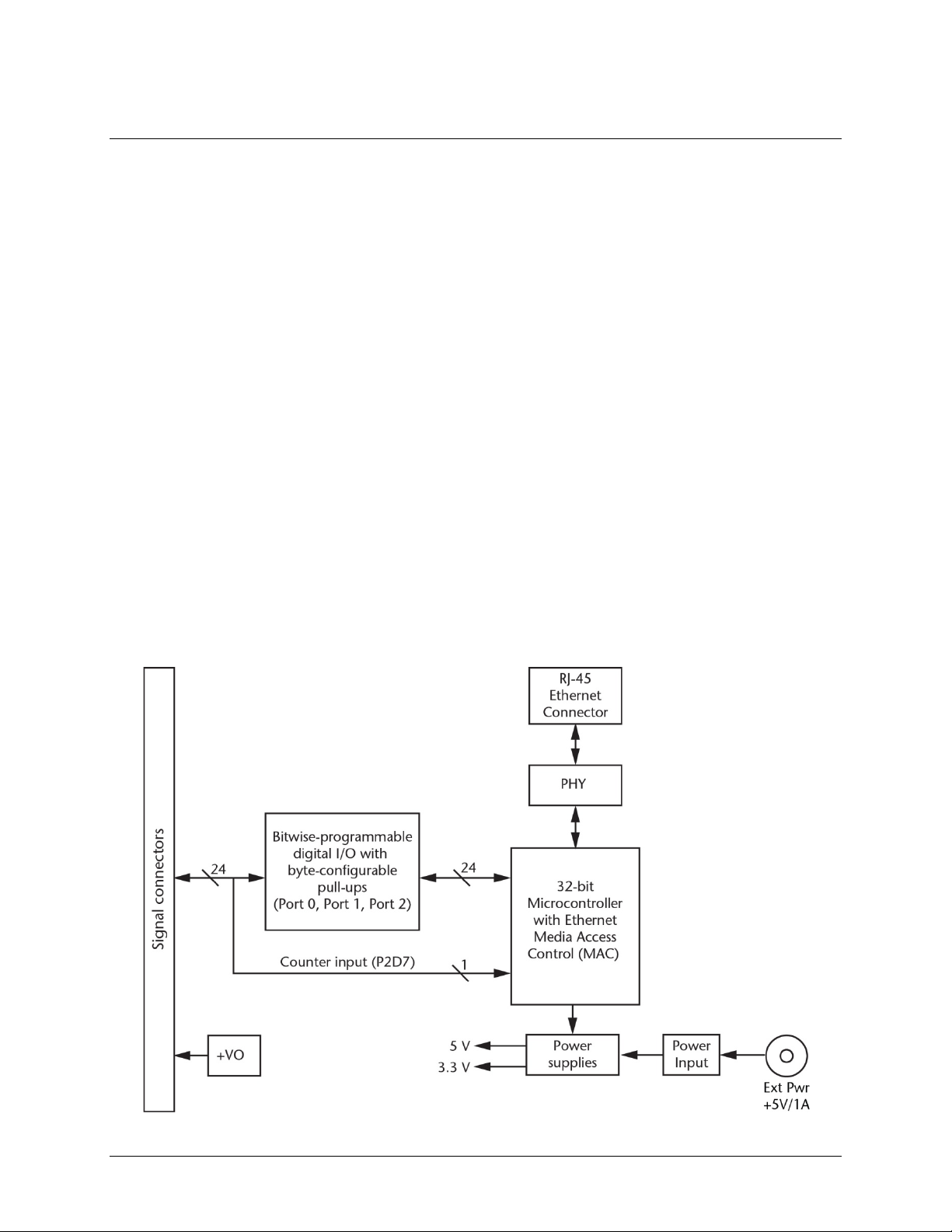
Functional block diagram
Preliminar
E-DIO24 functions are illustrated in the block diagram show n here.
Figure 1. Functional block diag ram
6

y
Chapter 2
Installing the E-DIO24
Unpacking
As with any electronic device, you should take care while handling to avoid damage from static
electricity. Before removing the device from its p ackaging, ground yourself using a wrist strap or by simply
touching the computer chassis or other grounded object to eliminate any stored static charge.
Contact us immediately if any components are missing or damaged.
Installing the software
Refer to the MCC DAQ Quick Star t for instructions on installing the software on the MCC DAQ CD. Refer to
the device product page on the Measurement C omputing website for i nformation about the included and
optional software supported by the E-DIO24.
Install the software before you install your device
The drive r needed to run the E-DIO24 is installed with the software. Therefore, you need to install the software
package you plan to use before you install the hardware.
Connecting the external pow e r a dapter
Power to the E-DIO24 is provided with the 5 volt, 1 amp external power adapter (PS-5V1AEPS). Connect the
adapter cord to the power connector on the E-DIO24, and plug the AC adapter into an electrical outlet.
Power LED turns on when 5 V power is supplied to the E-DIO24. If the voltage supply is le s s than 4.2 V
The
or more than 5.6 V, the
Power LED.
POWER LED does not turn on. Refer to Figure 3 on page 11 for the location of the
Preliminar
Connecting the E-DIO24
The E-DIO24 requires a TCP and UDP co nnection to a network or computer.
Using the Ethernet cable provided, connect the E-DIO24 to a 10Base-T- or 100Base-TX compatible Ethernet
port, hub, or switch. When connecting the E-DIO24 for the first time, make sure that you connect to a local
network with DHCP enabled. If you are unsure whether you have access to a local network or that DHCP is
enabled on t hat network, you should connect directly to a Windows PC.
It may take a minute or two for the network DHCP server to detect the device and assign an address. The green
Link/activity LED on the lower left of the Ethernet connector turns on when a valid Ethernet l ink is established,
and blinks when network activity is detected.
Once the E-DIO24 is physically connected to the local network or PC, you can run the software (InstaCal for
example) to establish a connection. If a connection cannot be established, make sure the device is using the
default configuration by following the instr uctions in the
Once a connection is established and you can communicate with the device, you can change the configuration
for other network scena rios.
Restoring factory default network settings on page 9.
7

E-DIO24 User's Guide Installing the E-DIO24
Configuring network se ttings
The following E-DIO24 network settings are software-selectable. One user at a time can connect to the device
and configure network options. The default settings are recommended for typical local networks.
Address mode
The address mode settings determine whether default IP parameters (IPv4 address, subnet mask, and gateway)
are assigned to the E-DIO24, or whether an a ut o-addressing method is used to assign these parameters.
DHCP or Link-Local enabled (default)
If connected to a network with a DHCP server, the service automatically assigns IP addresses to the E-DIO24.
If the connected network does not have a DHCP server, the address stored in the default IP address is assigned.
If the E-DIO24 is directly connected to a Windows PC or other host that supports link-local addressing, a linklocal address is a ssigned. A link-local address is valid only for communications between the E-DIO24 and the
PC to which it is connected.
DHCP Only
This setting enables configuration by a DHCP server, if one is available. The E-DIO24 is a ssigned an IP address
shortly after it is powered up and attached to the network.
Link-Local Only
The E-DIO24 is assigned a link-local IP address by the Windows PC or other host that supports link-local
addressing to which it is connected. A link-local address is valid only for communications between the
E-DIO24 and the PC to which it is connected.
Static
The default
IPv4 Address is manually configured on the E-DIO24.
IP address
The default IP address settings are assigned when automatic addressing is either disabled or not available
(DHCP or link-local, for example):
IPv4 address – The IP address stored on the device. The default IPv4 address is 192.168.0.101.
Subnet mask – The subnet mask st ored on the device. The subnet mask determines the number of bits of
the IP address that is used for the host portion of the address vs. the number of bits used for the network
portion. The default subnet mask is 255.255.255.000.
Gateway – The gateway IP address stored on the device. The gatewa y address o f the device bridges
subnets within a network. The default gateway is 192.168.0.1.
Connection code
The connection code is number between 0 (default) and 999999999. Change this number from its default to
prevent other users from connecting to and configuring the device. When the code is set to a value other than 0,
the device remains visible to other users on the network, b ut connection by another user is not allowed.
8

E-DIO24 User's Guide Installing the E-DIO24
Configuring the network r out e r for communication across networks
To communicate with the E-DIO24 from a computer connected to a different network – such as over the
Internet – you must change the network configuration of the netwo rk router.
Caution! This procedure should only be performed by a network administrator or computer professional.
Incorrect settings can significantly disr upt a network.
Complete the following steps to configure the network router for communication across networks. In this
procedure, the E-DIO24 is installed on the host LAN, and the computer is installed on the client LAN.
1. Connect the E-DIO24 to a local network and determine its IP ad dress.
If the address was assigned by DHCP, we recommend that you change it to a static address: set the default
address to the address assigned, and set the device network configuration to a static value.
2. Configure the firewall/router to forward incoming traffic to the following ports to the IP address assigned
to the device:
o UDP:54211 (discovery)
o TCP:54211 (commands)
3. On the computer connected to the client LAN, enter the WAN address of the host router, and specify the
ports that were forwarded to connect to the remote E-DIO24.
You can select a different port if the port a bove is not available on your router; however make s ure that the
same port is configured for both UDP and TCP.
Network alarm
You can configure a digital ou tput bit to change state when a host is connected to or disconnected from the
E-DIO24. All alarm settings are selectable with software.
Restoring factory default network settings
The reset button is used to restore the factory default network settings. T his button is located next to the LEDs
on the top edge of the enclosure; see Figure 3 on page 11.
To reset network configuration settings to factory default values, press and hold the
least four seconds until both the
up with network settings restored to the factory default values. If you release the button before the two LEDs
blink, the settings are not affected and the device starts up normally. If InstaCal is open w hen default s ettings
are restored, click the
Refresh Boards toolbar button to reflect the changes.
Power and Activity LEDs blink. When you release the button, the device starts
Factory reset button for at
Updating firmware
The E-DIO24 firmware can be updated in the field if required. Firmware available for download is posted at
www.mccdaq.com/firmware.aspx. MCC recommends that you check this page periodically to see if an update
to your device firmware is available.
Firmware update mode
If a firmware update fails, you can force the device into firmware update mode and use InstaCal to recover from
the failure.
To put the device into firmware update mode, press and hold the device reset button and apply power. The
device LEDs will continuously blink. InstaCal will detect a device in this mode as a bootloader device. Run
InstaCal and download the firmware. After downloading t he firmware, refresh the device list and add the device
to InstaCal again.
9

y
Functional Det ails
External components
The E-DIO24 has the following external components:
Screw terminals
LED status indicators
Ethernet connector
External power connector
Factory reset button
Screw terminals
The E-DIO24 device screw terminals provide the following connections:
Chapter 3
24 digital I/O connections (
One counter input (access with
One voltage output (
Ground (
The location of each signal is shown in Figure 2.
GND) connections
P0D0 to P2D7)
P2D7)
+VO)
Preliminar
Figure 2. E-DIO24 pinout
10
E-DIO24 User's Guide Functional Details
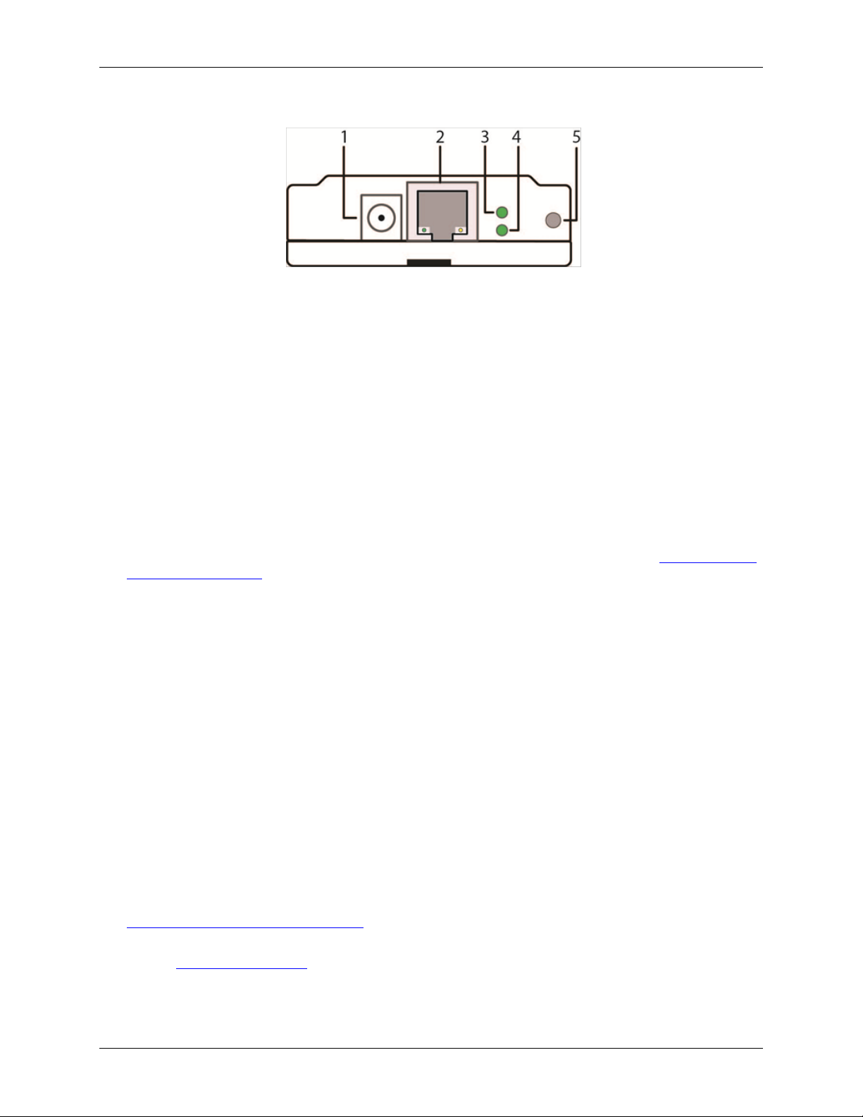
1
External power connector
4
Activity LED (bottom )
2
Ethernet connector with green Link/activity LED
(left) and yellow Speed LED (right)
5
Factory reset button
The remaining components are on the top edge of the enclosure; refer to Figure 3:
3 Power LED (top)
Figure 3. E-DIO24 connectors, reset button, and stat us LEDs
LED status indicators
The E-DIO24 has two LED indicators that indicate the status of power and host communications:
The
Power LED is on when external power between 4.2 V to 5.6 V is supplied.
This LED is off when the external p ower supply is not conn ected, or the input power is outside of the 4.2 V
to 5.6 V voltage range of the external supply, causing a power fault.
The E-DIO24 has an onboard voltage supervisory circuit that monitors the 5 V external power supply.
The
Activity LED is on when a valid host connection is detected.
This LED blinks when a command is received.
Both Power and Activity LEDs blink once when factory default settings are restored. Refer to
Restoring factory
default netwo rk se ttings on page 9 for more information.
Ethernet connector
The E-DIO24 has one 10/100 BASE-T, auto-negotiati on, high-speed communication port. The port connector is
an RJ-45, eight-position type that accepts CAT-5 shielded or unshielded twisted pair cable. The maximum
communication distance without using a repeater is 100 meters (328 feet). You can send your data 100 meters at
data speeds of up to 100 Mbps using only one Etherne t cable connected to the network.
Ethernet connector LEDS
The green Link/activity LED on the left of t he connector is on when a valid Ethernet link is established,
an
d blinks when network activity is detected.
The yellow
of
f when the transmission speed is 10 Mbps or no Ethernet link is est ablished.
Speed LED on the right of the connector is on when the transmission speed is 100 Mbps, and
External power connecto r
Connect the supplied 5 volt, 1 amp power adapter (PS-5V1AEPS) to this connector. The E-DIO24 requires
external power to operate.
Factory reset button
Use the factory reset button to restore network configuration settings to the factory default values. Refer to
Restoring factory default network settings on page 9 for instructions.
The reset button can also used to put the device into firmware update mode to recover if a firmware update fails.
Refer to
Firmware update mode section on page 9 for details.
11

E-DIO24 User's Guide Functional Details
Signal connections
Digital I/O
The E-DIO24 has 24 DIO lines configured as three 8-bit ports – port 0, port 1, and port 2. Each bit is
individually configurable for input or output. The digital I/O trans fer rate is 5 kHz, maximum for softwarepaced operation on a local network.
You can specify a digital bit configured for output as a network alarm and change state when an Ethernet
connection with a host is established or lost. All alarm settings are selectable with software.
The digital I/O terminals can detect the state of any TTL-level input signal with CMOS output . Refer to the
schematic s hown in Figure 4.
Figure 4. Schematic showing switch detection by digital channel P0D0
If you set the switch to the +5 V input, the digital bit reads TRUE (1). If you move the switch to GND, the bit
reads FALSE (0).
Hardware compatibility
The E-DIO24 is functionally equivalent to USB-DIO24 Series and USB-1024 Series hardware. Software
programs written for those hardware devices can be run with the E-DIO24.
Pull-up/down configuration
All DIO lines are pulled high by default to 5 V through 47 kΩ resistors via jumpe rs
circuit board (see Figure 5). Each jumper configures a digital port for pull-up or pull-down.
W3, W4, and W5 on the
Figure 5. Pull-up/down jumper locations
The pull-up/down voltage is common to all 47 kΩ resistors. Each jumper is configured by default for pull-up.
Figure 6 on page 13 shows the jumper con figured for pull-up and pull-down.
Caution! The discharge of static electricity can damage some electronic components. Take care when
removing the enclosure. Before t ouching the board, gr ound yourself using a wrist strap or touch
the computer chassis or other grounded object to eliminate any stored static charge.
12

E-DIO24 User's Guide Functional Details
Figure 6. Pull-up/down jumper configurations, typical
For more information about digital signal connections
For general information about d igital signal connections and digital I /O te chniques, refer to the Guide to DAQ
Signal Connections (available on our web site at www.mccdaq.com/pdfs/DAQ-Signal-Connections.pdf).
Counter input
The 32-bit event counter is ac cessed with digital port 2 bit 7 (P2D7). This pin accepts a frequency input up to
10 MHz The internal counter increments when the TTL levels t ransition from low to high.
Voltage output
The +VO termina l can output up to 10 mA maximum. You can use this terminal to supply power to external
devices or circuitry.
Caution! The +VO terminal is an output. Do not connect to an external power supply or you may damage
the device and possibly the computer.
Ground
The ground (GND) terminals provide a common ground for the digital I/O, counter input, and power output
terminal.
13

E-DIO24 User's Guide Functional Details
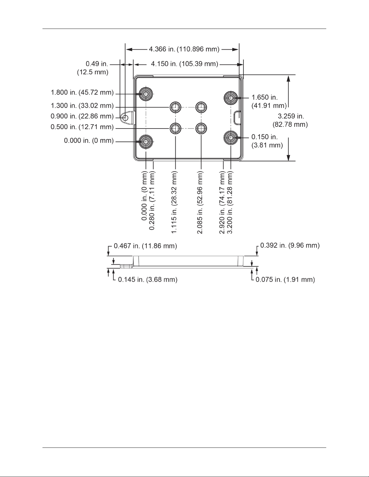
Mechanical drawings
Figure 7. E-DIO24 device circuit board dimensions
14
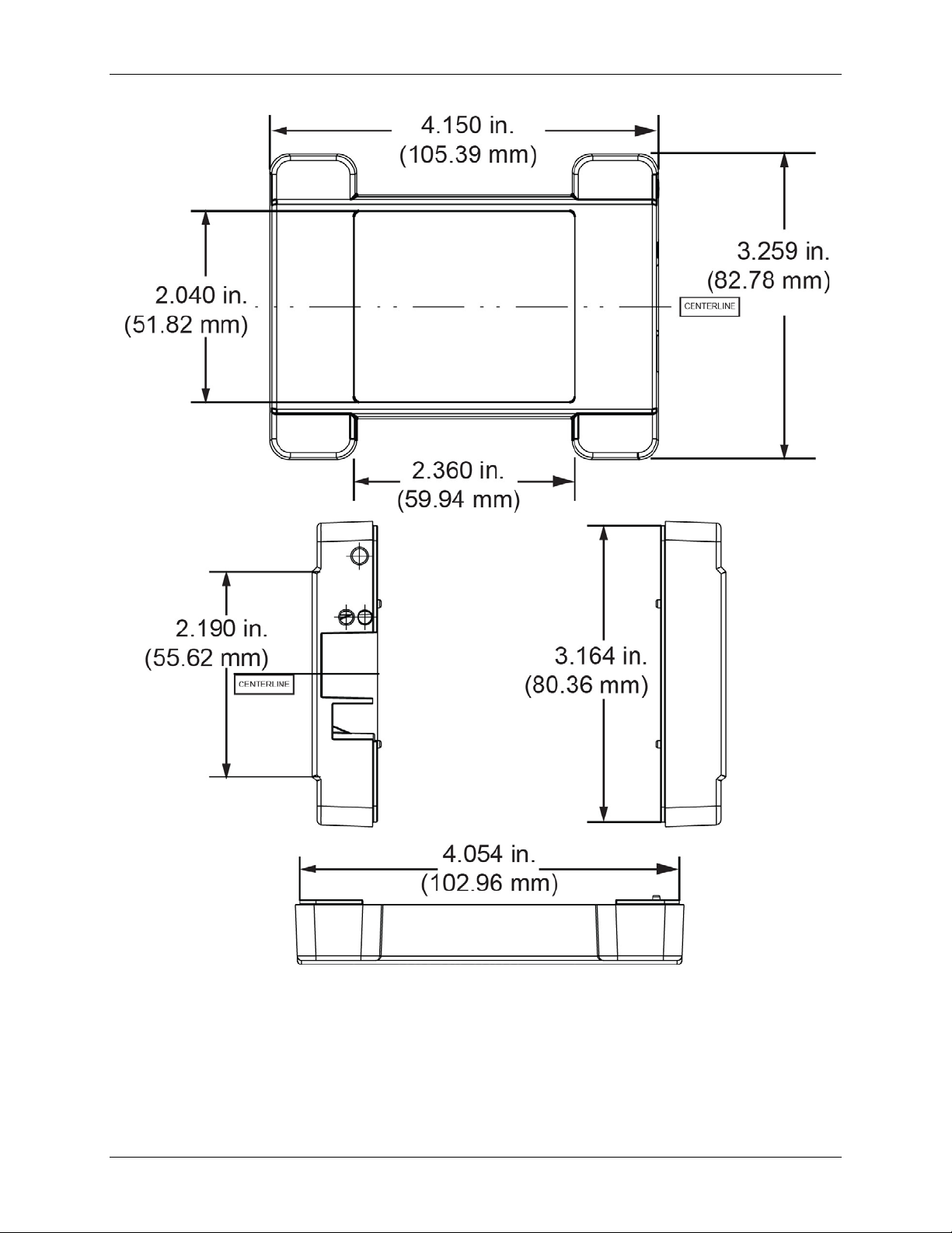
E-DIO24 User's Guide Functional Details
Figure 8. E-DIO24 bottom enclosure dimensions
15
E-DIO24 User's Guide Functional Details
Figure 9. E-DIO24 top enclosure dimensions
DIN-rail compatible
The E-DIO24can be mounted on a DIN rail using the ACC-205 DIN-rail accessory kit. Refer to our website for
more information.
16

Number of I/O
24, configured as 3 ports of 8 bits each (Port 0, Port 1, Port 2)
Configuration
Each bit can be independently configured for input or output
Each port has 47 kΩ resistors configurable as pull-up (default) or pull-down via
Digital I/O transfer rate
Any combination of DIO bits may be configured to become outputs and go to defined
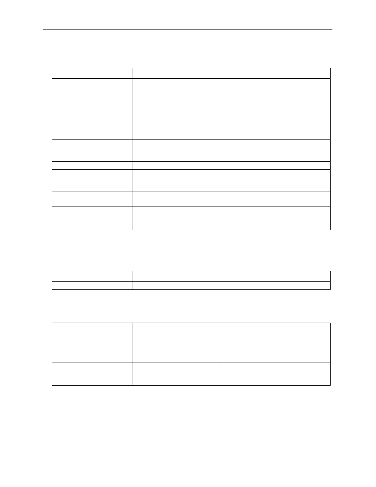
Power on and reset state
All bits are input unless the alarm functionality is enabled for them.
Input high voltage threshold
2.0 V min (Note 2)
Input high voltage limit
5.5 V absolute max
Input low voltage threshold
0.8 V max (Note 2)
–0.5 V absolute min
0 V recommended min
4.4 V min (IOH = –50 µA)
3.76 V min (IOH = –24 mA)
0.1 V max (IOL = 50 µA)
0.44 V max (IOL = 24 mA)
Specifications
All specifications are subject to change without notice.
Typical for 25 °C unless otherwise specified.
Specifications in italic text are guaranteed by design.
Digital input/output
Table 1. Digital input/output specifications
Parameter Specification
Digital type 5 V TTL input / CMOS output
Chapter 4
Pull-up configuration
(system-paced)
Alarm functionality
Input low voltage limit
Output high voltage
Output low voltage
Note 1: This is the typical throughput when the device and host are both connected by Ethernet to the same local
network. Throughput can vary significantly, and typical throughput is not guaranteed, if a wireless connection is
involved or data is sent over the internet.
Note 2: The digital input thresholds (P2D7 only) and counter input thresholds are different due to different buffer types.
internal jumpers W3 (port 1), W4 (port 2), and W5 (port 0).
100 to 5000 reads/writes per second, typical, on a local network (Note 1)
values when an Ethernet connection with a host is established or lost.
17
E-DIO24 User's Guide Specifications
Pin name
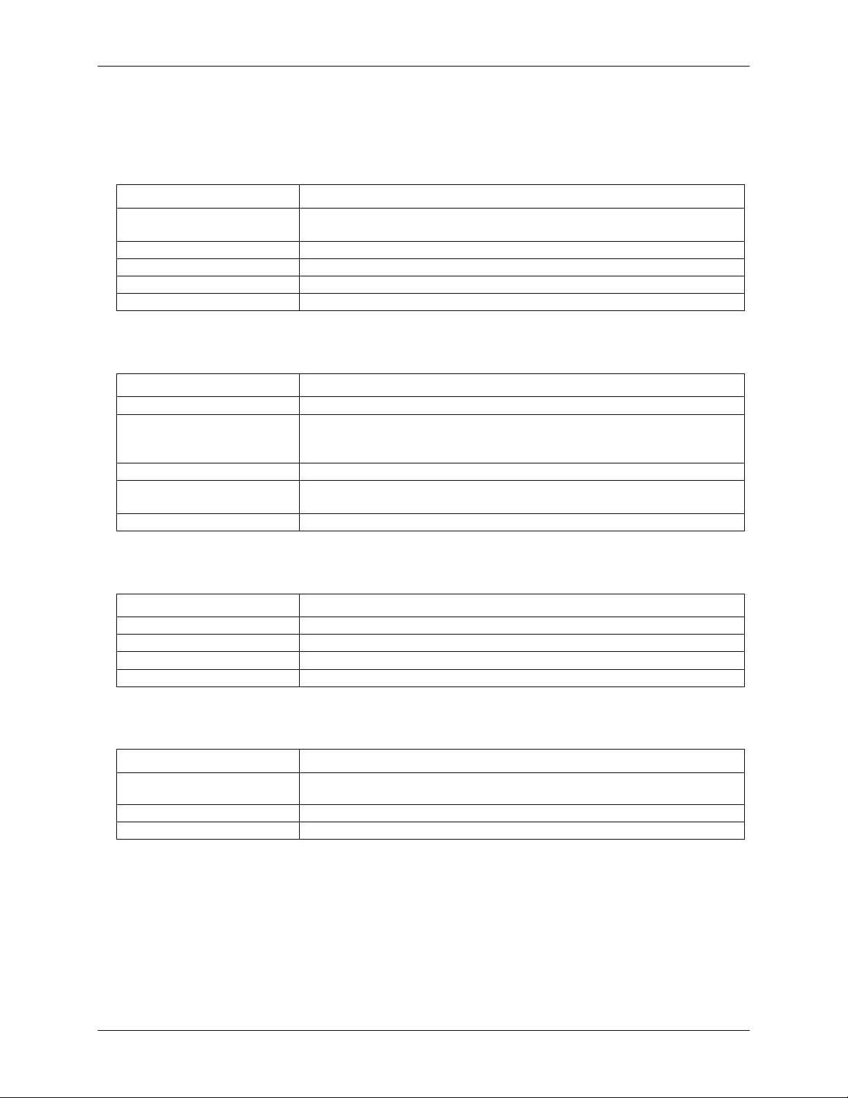
P2D7 (shared with digital I/O)
Counter type
Event counter
Number of channels
1
Input type
Schmitt trigger; uses port 2 digital I/O pull-up/down selection.
Resolution
32 bits
Input high voltage threshold
2.43 V typ (Note 3)
3.1 V max
Input high voltage limit
5.5 V absolute max
Input low voltage threshold
1.42 V typ (Note 3)
Input low voltage limit
–0.5 V absolute min
Input frequency
10 MHz max
High pulse width
50 ns min
Low pulse width
50 ns min
Non-volatile memory
4,096 bytes (272 bytes for settings, 3,824 bytes for user)
External power supply
5 V ±5% required
5 V, 1 A supply provided (PS-5V1AEPS)
Supply current
Quiescent current
160 mA typical (Note 4)
User output voltage range
Available at +VO terminal
4.40 V min to 5.25 V max; assumes supplied
User output current
Available at +VO terminal
10 mA max
Counter
Table 2. Counter specifications
Parameter Specification
Schmitt trigger hysteresis 1.01 V typ
0.6 V min
1.5 V max
1.9 V min
1.0 V min
2.0 V max
0 V recommended min
Note 3: The digital input thresholds (P2D7 only) and counter thresholds are different due to different buffer types.
Memory
Table 3. Memory specifications
Parameter Specification
Power
Table 4. Power specifications
Parameter Condition Specification
840 mA max, including all external loading
AC adapter is used
Note 4: This is the total quiescen t current requirement for th e device that includes the LEDs. This value does not
include any potential loading of the digital I/O bits or +VO terminal.
18
E-DIO24 User's Guide Specifications
100 Base-TX
10 Base-T
Communication rates
10/100 Mbps, auto-negotiated
Connector
RJ-45, 8 position
Cable length
100 meters (328 feet) max
Additional parameters
HP Auto-MDIX support
Protocols used
TCP (IPv4 only) and UDP
UDP: 54211 (discovery)
Network IP configuration
DHCP + link-local, DHCP, static, link-local
Network name publication
By NBNS; responds to b-node broadcasts, therefore only available on the local subnet
Factory default IP address
192.168.0.101
Factory default subnet mask
255.255.255.0
Factory default Gateway
192.168.0.1
Factory default DHCP setting
DHCP + link-local enabled
TCP sockets are not opened unless application sends the correct PIN connection
Number of concurrent sessions
1
Vulnerabilities
TCP Sequence Number Approximation Vulnerability
Network
Ethernet connection
Table 5. Ethernet connection specifications
Parameter Specification
Ethernet type
Network interface
Table 6. Factory default specifications
Parameter Specification
Network ports used
Network name
UDP: 6234 (bootloa de r onl y)
TCP: 54211 (commands)
E-DIO24-xxxxxx, where xxxxxx are the lower 6 digits of the device MAC
address
Network factory default settings
Table 7. Factory default specifications
Parameter Specification
Network security
Table 8. Factory default specifications
Parameter Specification
Security implementation
code; stored in non-volatile memory; may be changed by user; default value is 0000
19

E-DIO24 User's Guide Specifications
4.2 V < V
< 5.6 V: On
On when there is a valid host connection.
Both LEDs blinking continuously: In firmware update mode.
Left (green) – Link/activity indicator: on when there is a valid Ethernet link, and
Right (yellow) – Speed indicator: on f or 100 Mbps, off for 10 Mbps or no link.
Resets network and alar m configuration settings to factory default values.
constantly. The device may be returned to normal operation by cycling the power .
Storage temperature range
–40 °C to 85 °C max
Humidity
0% to 90% non-condensing max
Dimensions (L × W × H)
117.9 × 82.8 × 29.0 mm (4.64 × 3.26 × 1.14 in.)
LED displays and the factory reset button
Table 9. LED and button configurations
Parameter Specification
Power LED (top)
V
ext
Both LEDs blinking continuously: In firmware update mode
ext
< 4.2 V, V
> 5.6 V: Off (power fault)
ext
Activity LED (bottom)
Ethernet connector LEDS
Blinks when a command is received.
blinks when network activity is detected.
Press and hold for 4 seconds. The Power and Activity LEDs will both blink twice
and turn off to indicate that network settings have been restored to default values.
Factory reset button
Release the button to allow the device to reset and u se th e default settings.
If the reset button is released before the two LEDs bli nk, settings are not affected.
Holding the reset button at power on forces the device into firmware update mode
in case of a failed firmware update. In this mode, both LEDs blink together
Environmental
Table 10. Environmental speci ficat ion s
Parameter Specification
Operating temperature range 0 °C to 55 °C max
Mechanical
Table 11. Mechanical specif ic ation s
Parameter Specification
20

E-DIO24 User's Guide Specifications
Connector type
Screw terminal
Wire gauge range
16 AWG to 30 AWG
Pin
Signal name
Pin description
Pin
Signal name
Pin description
1
P0D0
Port 0 bit 0
17
P1D0
Port 1 bit 0
3
P0D2
Port 0 bit 2
19
P1D2
Port 1 bit 2
5
GND
Ground
21
GND
Ground
6
P0D4
Port 0 bit 4
22
P1D4
Port 1 bit 4
7
P0D5
Port 0 bit 5
23
P1D5
Port 1 bit 5
8
P0D6
Port 0 bit 6
24
P1D6
Port 1 bit 6
9
P0D7
Port 0 bit 7
25
P1D7
Port 1 bit 7
10
GND
Ground
26
+VO
User voltage output
11
GND
Ground
27
GND
Ground
12
P2D0
Port 2 bit 0
28
P2D4
Port 2 bit 4
14
P2D2
Port 2 bit 2
30
P2D6
Port 2 bit 6
16
GND
Ground
32
GND
Ground
Signal connector
Table 12. Screw terminal connector specifications
Parameter Specification
Table 13. Screw terminal pinout
2 P0D1 Port 0 bit 1 18 P1D1 Port 1 bit 1
4 P0D3 Port 0 bit 3 20 P1D3 Port 1 bit 3
13 P2D1 Port 2 bit 1 29 P2D5 Port 2 bit 5
15 P2D3 Port 2 bit 3 31 P2D7 Port 2 bit 7 / Counter
21

Declaration of Conformity
According to ISO/IEC 17050-1:2010
Manufacturer: Measurement Computing Corporation
Address: 10 Commerce Way
Suite 1008
Norton, MA 02766
USA
Product Cate gory: Electrical equipment for measurement, control and laboratory use.
Date and Place of Issue: October 15, 2015, Norton, Massachusetts USA
Test Report Number: EMI6779.15
Measurement Computing Corporation declares under sole responsibility that the product
E-DIO24
Complies with the essential requirements of the following applicable European Directives:
Electromagnetic Compatibility (EMC) Directive 2004/108/EC
Low Voltage Directive 2006/9 5/EC
RoHS Directive 2011/65/EU
Conformity is assessed in accordance to the following standards:
EMC:
Emissions:
EN 61326-1:2013 (IEC 61326-1:2012), Class A
EN 55011: 2009 + A1:2010 (IEC CISPR 11:2009 + A1:2010), Group 1, Class A
Immunity:
EN 61326-1:2013 (IEC 61326-1:2012), Controlled EM Environments
EN 61000-4-2:2008 (IEC 61000-4-2:2008)
EN 61000-4-3 :2010 (IEC61000-4-3:2010)
EN 61000-4-4 :2012 (IEC61000-4-4:2012)
EN 61000-4-5 :2005 (IEC61000-4-5:2005)
EN 61000-4-6 :2013 (IEC61000-4-6:2013)
EN 61000-4-11:2004 (IEC61000-4-11:2004)
Safety:
EN 61010-1 (IEC 61010-1)
Environmental Affairs:
Articles manufactured on or after the Date of Issue of this Declaration of Conformity do not contain any of the
restricted substances in concentrations/applications not permitted by the RoHS Directive.
Carl Haapaoja, Director of Quality Assurance

Measurement Computing Corporation
www.mccdaq.com
NI Hungary Kft
10 Commerce Way
Norton, Massachusetts 02766
(508) 946-5100
Fax: (508) 946-9500
E-mail:
info@mccdaq.com
H-4031 Debrecen, Hátar út 1/A, Hungary
Phone: +36 (52) 515400
Fax: +36 (52) 515414
http://hungary.ni.com/debrecen
 Loading...