

Page 1
1300 Henley Court
Pullman, WA 99163
509.334.6306
www.digilentinc.com
I/O Explorer™ USB Reference Manual
Revised April 15, 2016
This manual applies to the I/O Explorer USB rev. C
DOC#: 502-174
Copyright Digilent, Inc. All rights reserved.
Other product and company names mentioned may be trademarks of their respective owners.
Page 1 of 16
The I/O Explorer board.
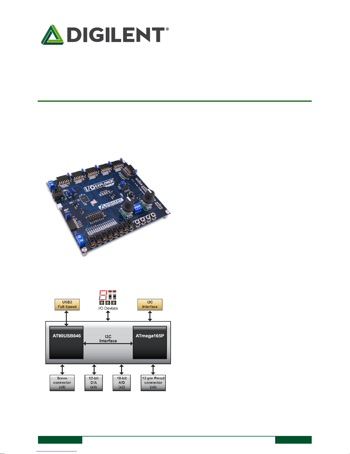
I/O Explorer USB block diagram.
Features include:
Two Atmel AVR microcontrollers:
AT90USB646 and ATmega165P
USB 2.0 Full Speed device
Fully software compatible with the Digilent
Adept Runtime system
C/C++/C#/Visual Basic callable API set using
the Digilent Adept System Software
Developer’s Kit (SDK)
5 12-pin and 1 6-pin Pmod ports
16 discrete LEDs
8 slide switches
4 push button switches
4 position DIP switch
2 rotary encoders with integral push button
speaker/buzzer
Two 10-bit A/D inputs
Four 12-bit D/A outputs
Up to 52 digital input/output pins
Connectors for up to 8 RC servos
1 hardware SPI master port
Up to 3 additional software SPI master ports
UART interface port
Provision for 4 additional RC servos using
Digilent PmodCON3
Provision for 2 additional quadrature
encoders via Pmod port
Provision for up to 8 additional 10-bit A/D
inputs using servo connectors
Multiple power supply options, including USB
powered
ESD protection and short circuit protection for
all I/O pins.
Overview
The Digilent I/O Explorer USB is a USB peripheral device that allows programmatic access from a personal
computer to various external Input/Output (I/O) devices.
Using the Digilent Adept Software Developer's Kit (SDK) and the Digilent Adept Runtime System it is possible to
write application programs running under either the Microsoft Windows or Linux operating systems that perform
Page 2

I/O Explorer™ USB Reference Manual
Copyright Digilent, Inc. All rights reserved.
Other product and company names mentioned may be trademarks of their respective owners.
Page 2 of 16
various kinds of I/O operations to devices on the I/O Explorer board itself, or through the I/O Explorer to devices
external to the computer.
The I/O Explorer provides a number of I/O devices on the board itself, as well as RC servo connectors, and Digilent
Pmod ports that allow access to devices external to the I/O Explorer.
In addition to its use as a dedicated USB peripheral device, the I/O Explorer can also be used as a microcontroller
development board. It features two Atmel AVR microcontrollers, one having USB device capability. Digilent makes
available the firmware images needed to restore it to the factory configuration as a USB peripheral device if it has
been reprogrammed with user defined firmware.
1 Functional Description
The Digilent USB I/O Explorer is a microcontroller board that is designed to be used as a USB peripheral device to
expand the I/O capabilities of a PC running either the Microsoft Windows operating system or the Linux operating
system. The Digilent Adept Software System provides the run-time software for operation of the board, and the
Digilent Adept Software Development Kit (SDK) allows the user to write custom application software to access and
control its features. The Digilent Adept SDK comes with a variety of sample programs that illustrate operation of
various features of the I/O Explorer.
The I/O Explorer provides a number of built-in I/O devices, such as switches, push buttons, LEDs, rotary encoders,
and a speaker/buzzer. It also provides a number of connectors that allow access to and control of devices external
to the I/O Explorer.
Operation of the I/O Explorer board as a Digilent Adept compatible device requires the installation of the Digilent
Adept software available for download from the Digilent web site: www.digilentinc.com. In addition to
downloading and installing the Digilent Adept software, the Digilent Adept SDK must be downloaded and installed
in order to make effective use of the board.
In addition to the Digilent Adept SDK, the user will require some software development tool that allows writing
application programs on the target operating system. The Digilent Adept System uses the C programming language
calling conventions and any development tool that provides the ability to call C functions in a DLL (on Windows) or
a shared library (on Linux) can be used. Some version of Microsoft Visual Studio is commonly used on Windows,
and some version of the GCC tool chain is normally used on Linux.
In addition to the primary design purpose of being a dedicated USB peripheral device, the I/O Explorer can also be
used as a microcontroller development board. The I/O Explorer contains two Atmel AVR microcontrollers: IC1, the
primary microcontroller is an AT90USB646 AVR microcontroller with USB capability; IC2, the secondary
microcontroller is an ATmega165P AVR device.
Development of custom firmware to run on the I/O Explorer requires the use of some development tool that
supports the Atmel AVR microcontroller family. The most common tool used is the free Atmel AVR Studio IDE and
assembler available for download from the Atmel web site. The free GCC based WinAVR C compiler system can be
used with Atmel’s AVR Studio and provides a very powerful C language programming environment. WinAVR is
available for free download from the internet from various sources.
In addition to the development tool software, using the I/O Explorer as a microcontroller development platform
requires a programming cable, or in-system-debugger to load the user firmware into the microcontroller. The I/O
Explorer is designed to allow use of the Atmel JTAG-ICE mk II or the Atmel AVR Dragon for in-system debug. In-
Page 3

I/O Explorer™ USB Reference Manual
Copyright Digilent, Inc. All rights reserved.
Other product and company names mentioned may be trademarks of their respective owners.
Page 3 of 16
system programming is normally accomplished using a Digilent programming cable, either the Digilent JTAG-USB
Programming Cable, or the Digilent JTAG-USB Full Speed Module. The use of an Atmel ISP In System Programmer is
also supported with the use of a suitable flying-lead cable (e.g. Digilent 6 Pin MTE Cable) to convert from the
Digilent 1x6 programming connector convention to the Atmel 2x3 connector convention.
For additional information useful in developing custom firmware for the board, the complete schematic is available
on the Digilent web site.
2 Power Supply
The I/O Explorer may be used either as a USB bus powered device or as a self powered device. Jumper JP6 is used
to select between these two options. Install a shorting block in the VUSB position for USB bus power. Install a
shorting block in the VEXT position for self power.
Power switch, SW10, is used to turn board power on or off. Ensure that the power switch is in the ON position to
operate the board.
When operating as a bus powered device, care should be taken in powering devices external to the I/O Explorer.
The 5V USB bus power supply is available at the Pmod ports and other points on the board. Care should be taken
not to exceed the 500mA current limit that USB bus powered devices are allowed to consume. Care should
particularly be taken not to short the USB 5V supply to ground or external voltage supplies as this could result in
damage to the USB hub or PC motherboard to which the I/O Explorer is connected.
When operating as a self powered device, there are three power supply connectors on the I/O Explorer for
connecting the external power supply: J13, J14, and J15. These three connectors are wired in parallel and only one
of the three should be used at a time.
The barrel connector, J13, will normally be used for desktop applications as a self powered device. J13 is the
connector used by the AC supply adapter optionally available from Digilent, or other sources. J13 is a 2.5mm x
5.5mm coaxial connector wired with the center terminal as the positive voltage.
J14 is a screw terminal connector for use with higher current battery packs, bench supplies or other power sources
where use of a hard wired power supply is desirable.
J15 is a two-pin male header that provides easy battery or battery-pack connection. Digilent has both two-cell and
four-cell AA battery holders with two pin connectors available for connection to J14.
The main operating voltage of the I/O Explorer can be selected between one of two voltages. Jumper JP7 is used to
select between these two voltages. With JP7 in the 3V3 position, the main board power bus is powered from the
output of the 3.3V main power supply regulator on the board. When JP7 is in the 5V0 position, the main power
supply regulator is bypassed, and the main board power bus is powered directly from the applied supply voltage.
When operating as a USB bus powered device, this will be the USB bus 5.0V power supply. When operating as a
self powered device, this will be the voltage of the external supply. In this case, the external supply should not
exceed 5.5V or damage to the board will result.
The main power supply regulator on the I/O Explorer is rated for external power from 3.6 to 9 volts DC. Using a
voltage outside this range could damage the board and connected devices.
The I/O Explorer has a second screw terminal connector, J10 that supplies power to the servo power bus, VS, to
power the RC hobby servo connectors. This allows servos to be powered from a separate power supply than the
Page 4

I/O Explorer™ USB Reference Manual
Copyright Digilent, Inc. All rights reserved.
Other product and company names mentioned may be trademarks of their respective owners.
Page 4 of 16
one powering the electronics on the I/O Explorer. This can be useful when using servos that require large amounts
of power. See the section on Servo Connectors below for a discussion of the options available for powering the VS
bus.
Jumper JP3 can be used to connect the I/O Explorer unregulated power bus VU to the servo power bus, VS. When
no shorting block is installed on JP3, the VU and VS busses are separate. When a shorting block is on JP3, the two
busses are joined and the VU bus can be powered in any of the previously indicated ways, or from connector J10.
The I/O Explorer can provide power to any peripheral modules attached to the Pmod ports and to I2C devices
powered from the I2C daisy chain connector, J12.
Each Pmod port provides power pins that can be powered from either unregulated voltage, VU, or regulated
voltage, 3V3, by setting the voltage jumper block to the desired position. Note that when the operating voltage
select jumper JP7 is in the 5V0 position, the USB or external power supply voltage will be supplied to the Pmod
ports regardless of the position of the voltage select jumpers at the connectors.
The I2C power connectors provides 3.3V when the main board operating voltage (selected by JP7) is 3.3V, or the
external supply voltage when JP7 is in the 5V0 position.
The 3.3V supply provided to the Pmod and I2C connectors is provided by the onboard voltage regulator. This
regulator is capable of providing a maximum of 500mA of current. The circuitry on the I/O Explorer will consume
less than 100mA in normal operation. The remaining current is available to provide power to attached Pmod and
I2C devices. The regulator is on the bottom of the board, near the power connectors, and will get warm when the
amount of current being used is close to its limit.
3 USB Operation
When operating using the normal factory firmware, the I/O Explorer functions as a USB 2.0 compliant full speed
device. Normal operation requires installation of the Digilent Adept Runtime software system, and it is accessible
to applications software developed using the Digilent Adept Software Developer’s Kit (SDK). The Digilent Adept
Software Developer’s Kit and the Digilent Adept Runtime system is available for download from the Digilent web
site: www.digilentinc.com
By replacing the factory firmware with end-user developed firmware, the I/O Explorer can function as a user
defined USB device.
The primary microcontroller (AT90USB646) contains a USB 2.0 Compliant, Full Speed Device controller. Refer to
the Atmel data sheet for the AT90USB646 and the USB 2.0 Specification for information on developing USB device
firmware.
4 On-board I/O Devices
The I/O Explorer provides the following I/O Devices on the board:
8 Slide switches
4 Push button switches
4 Position DIP switch
16 Discrete LEDs
Page 5

I/O Explorer™ USB Reference Manual
Copyright Digilent, Inc. All rights reserved.
Other product and company names mentioned may be trademarks of their respective owners.
Page 5 of 16
2 Rotary encoders with integral push buttons
Speaker/Buzzer
When operating the I/O Explorer using the factory firmware, these devices are accessible using the DGIO API set as
described in the DGIO Programmer’s Reference Manual contained in the Digilent Adept SDK. Refer to the section
Digilent Adept Port Descriptions below for details on the ports used for access to the on-board I/O devices.
5 Pmod Ports
The I/O Explorer has six Pmod ports for connecting Digilent peripheral modules. There are two styles of Pmod
ports: six-pin and twelve-pin. Both ports use standard pin headers with 100mil spaced pins. The six-pin ports have
the pins in a 1x6 configuration, while the twelve-pin ports use a 2x6 configuration. The six-pin ports provide four
I/O signals, ground, and a switchable power connection. The twelve-pin ports provide eight I/O signals, two
power, and two ground pins. The twelve-pin ports have the signals arranged so that one twelve-pin port is
equivalent to two of the six-pin ports. The power connection is switchable between the regulated 3.3V main board
supply and the unregulated input supply.
When operating the I/O Explorer using the factory firmware, the Pmod ports are accessible via a number of the API
sets provided by the Digilent Adept SDK. In addition to the other ways that they can be used, the I/O pins on the
Pmod ports can be accessed for direct pin input or output using the DPIO API functions described in the DPIO
Programmer’s Reference Manual contained in the Digilent Adept SDK. Refer to the section Digilent Adept Port
Descriptions below for information on the various ways that the Pmod ports are used.
Digilent Pmod peripheral modules can either be plugged directly into the ports on the I/O Explorer or attached via
cables. Digilent has a variety of Pmod interconnect cables available.
See the “Connector and Jumper Block Pinout Tables” section below for more information about connecting
peripheral modules and other devices to the I/O Explorer. These tables describe the relationship between the
various Adept software interfaces and the signals available on the connector pins.
6 Analog Inputs and Outputs
The I/O Explorer provides analog input channels and analog output channels via Analog to Digital (A/D) and Digital
to Analog (D/A) converters on the board. When using the factory firmware, these analog inputs and outputs are
accessed using the DAIO API functions provided by the Digilent Adept SDK and described in the DAIO
Programmer’s Reference Manual.
The A/D converters for the analog input channels are provided by the built-in A/D converters in the two
microcontrollers.
The two analog input channels accessible through DAIO port 0 are provided by the A/D converter in the primary
microcontroller. This port supports single sample input mode as well as continuous sampling input mode. These
two analog input channels have input protection diodes to protect from out-of-range input voltages and band
limiting input filters with a cutoff frequency of 2Khz. This port supports sample rates up to 4K samples per second.
This analog input port supports two selectable internal voltage references (2.56V and 3.3V) as well as an external
reference that can be applied to the AREF1 pin on connector J2.
Page 6

I/O Explorer™ USB Reference Manual
Copyright Digilent, Inc. All rights reserved.
Other product and company names mentioned may be trademarks of their respective owners.
Page 6 of 16
The analog inputs for DAIO port 0 are accessed via connectors JF and J1.
The eight analog input channels accessible through DAIO port 1 are provided by the A/D converter in the
secondary microcontroller. This port supports only single sample input mode. The inputs on this port are available
using the servo connectors S1-S8. These connectors and the corresponding I/O pins on the microcontroller are
shared between DAIO port 0, DPIO port 6, and DEMC port 3.
This analog input port supports two selectable internal voltage references (1.1V and 3.3V) as well as an external
reference that can be applied to the AREF2 pin on connector J5.
The four analog output channels accessible through DAIO port 2 are provided by a Microchip MCP4728 serial D/A
converter. This port supports only single sample output mode. The analog outputs for DAIO port 2 are accessible
via connectors JF and J1.
This analog output port supports two selectable voltage references (2.048V and 3.3V).
7 UART Interface
The I/O Explorer provides a Universal Asynchronous Receiver/Transmiter (UART) interface for asynchronous serial
communications.
The I/O signals for the UART interface are provided on Pmod connector JG. When using the factory firmware, the
UART interface is accessed using the DACI API functions provided in the Digilent Adept SDK and are described in
the DAIO Programmer’s Reference Manual. The UART interface is accessed as DACI port 0.
The signals provided at connector JG are logic level signals. If RS232 signal levels are required, a Digilent
PmodRS232 can be attached to connector JG to provide the level translation and a DB9 connector for connection
to standard RS232 serial devices.
8 RC Servo Connectors
The I/O Explorer provides eight 3-pin RC hobby servo connectors for direct control of servos in embedded
hardware actuator applications. The servo connectors are labeled S1-S8 and are accessible via the Adept system
DEMC servo interface. When programmed directly, the servo connectors are connected to the secondary
microcontroller. The servo connectors S1-S8 are accessible via DEMC port 3.
In addition to the on-board servo connectors, a second servo port, DEMC port 4, provides four additional servo
channels. This servo port can be used with a Digilent servo connector module, PmodCON3, connected to pins 7-12
of Pmod connector JE.
RC servos use a pulse width modulated signal, PWM, to control the servo position. When directly programming
the secondary microcontroller, the servo connectors on the I/O Explorer board are intended to be driven using
timer interrupts rather than directly by the pulse width modulators in the internal timers. Digilent has a reference
design available that illustrates using timer interrupts to control signal timing for the PWM signals to control RC
servos.
Page 7

I/O Explorer™ USB Reference Manual
Copyright Digilent, Inc. All rights reserved.
Other product and company names mentioned may be trademarks of their respective owners.
Page 7 of 16
SCL
SDA
SCL
SDA
Pull-ups
Enabled
Pull-ups
Disabled
3V3
GND
3V3
GND
There are three power options for servo connections: a common power bus (VU) for the I/O Explorer and servos;
separate on-board power busses for the I/O Explorer (VU) and the servos (VS); or an on-board power bus for the
I/O Explorer (VU) an external power bus for servos.
For the first case above: Install a shorting block on JP3 to connect the VS servo power bus to the VU power bus.
The servo power bus is then powered from the same source as the VU power bus. Powering a large number of
servos from USB power is not recommended. USB should only be used to power a couple of servos to avoid
exceeding the 500mA that a USB device is allowed to use.
For the second case above: Remove the shorting block from jumper JP3 to make the VS servo power bus
independent from the VU bus. In this case, the VS bus is powered from screw terminal connector J10.
Finally, for very high servo current applications, a separate power bus external to the I/O Explorer can be used to
provide servo power. In this case, remove the shorting block on JP1, tie the external servo power bus ground to
the I/O Explorer ground through the ground terminal on J10, and use pin 1 on the servo connectors to bring the
servo control signals out to the servos. The servo power and ground connections are made off-board.
The on-board servo power bus can be used to provide a maximum of 2A to each servo connector and 5A total to all
servo connectors.
9 Digilent Two Wire Serial Interface (DTWI)
The Digilent Two Wire Serial Interface (DTWI) provides a medium speed serial comunications interface compatible
with the Inter-Integrated Circuit (I2CTM) Interface defined by Philips. The I2C interface provides master and slave
operation using 7 bit device addressing. Each device is given a unique address, and the protocol provides the
ability to address packets to a specific device or to broadcast packets to all devices on the bus.
Access to the DTWI bus is provided using the DTWI API functions as described in the DTWI Programmer’s
Reference Manual in the Digilent Adept SDK.The DTWI connector, J12, provides two positions for connecting to the
I2C signals, power and ground. By using two-wire or four-wire MTE cables (available separately from Digilent) a
daisy chain of multiple I2C-compatible devices can be created.
The I2C bus is an open-collector bus. Devices on the bus actively drive the signals low. The high state on the I2C
signals is achieved by pull-up resistors when no device is driving the lines low. One device on the I2C bus must
provide the pull-up resistors. The I2C bus on the I/O Explorer provides selectable pull-up resistors that can be
enabled or disabled via jumper blocks JP4 and JP5. The pull-ups are enabled by installing shorting blocks and are
disabled by removing the shorting blocks. The shorting blocks are placed so that they line up with the SCL and SDA
labels on the board. Only one device on the bus should have the pull-ups enabled.
Jumper settings for I2C pull-up resistors.
Page 8

I/O Explorer™ USB Reference Manual
Copyright Digilent, Inc. All rights reserved.
Other product and company names mentioned may be trademarks of their respective owners.
Page 8 of 16
10 Private I2C Bus
When the I/O Explorer is operating using user developed firmware in the primary microcontroller, there is a
private I2C bus controlled by the primary microcontroller that is used to talk to two peripheral devices: The
secondary microcontroller, and the Microchip MCP4728 Digital to Analog (D/A) converter.
When running the factory firmware in the secondary microcontroller, this microcontroller appears as an I2C slave
device on the private bus. The command protocol for this interface is described in the document: Digilent I/O
Explorer Slave Device Communications Protocol available on the Digilent web site. This document is contained in
the reference design example that illustrates the used of the command protocol to talk to the secondary
microcontroller. The primary microcontroller can send commands to the secondary microcontroller for access to
many of the on-board I/O devices, such as the switches, push buttons, LEDs, etc.
In addition to the secondary microcontroller, there is also a Microchip MCP4728, four channel, D/A converter on
the private I2C bus. When using the factory firmware in the primary microcontroller, this D/A converter provides
the analog outputs accessible through the DAIO API functions. When running user defined firmware on the
primary microcontroller, this device is directly accessible to the user firmware.
The AT90USB646 microcontroller has a single TWI controller. This TWI controller is used to provide the public
DTWI (I2C) interface, and is not used for the private I2C bus. The private I2C bus is controlled using a ‘bit-banged’
software I2C implementation. Digilent provides a reference design example as part of the I/O Explorer support
documentation to illustrate this ‘bit-banged’ I2C implementation.
11 Developing Custom Firmware for the I/O Explorer
Although the I/O Explorer is primarily intended to function as a dedicated USB peripheral device to provide I/O
expansion capability for PC application programs, it can also be used as a microcontroller development platform to
run user developed custom firmware.
Connectors are provided for in-system-programming and for debugging firmware running on each microcontroller.
Connectors JP1 and J3 are the programming and debugging connectors respectively for the primary
microcontroller, IC1, an Atmel AT90USB646. Connectors JP2 and J6 are the programming and debugging
connectors respectively for the secondary microcontroller, IC2, an Atmel ATmega165P.
The programming connectors are intended for use with a Digilent JTAG/SPI programming cable, such as the
Digilent JTAG-USB Full Speed Module, although other programmers can be used with a suitable connector adapter.
The debugging connectors are suitable for use with an Atmel JTAG ICE mk II or an Atmel AVR Dragon for in-system
programming and debugging.
In order to restore the I/O Explorer to its original functionality after having programmed it with custom firmware,
it is necessary to re-program the original firmware into whichever of the two microcontrollers have been
programmed with custom firmware. Digilent makes the factory firmware images available as part of the support
documents for the I/O Explorer on the Digilent web site. There are two firmware image files for each
microcontroller: one to restore the program flash memory, and one to restore the EEPROM. Both firmware images
must be programmed into the microcontroller.
The filenames for the firmware image files for the primary microcontroller are of the form:
AvrFW_29_000003F2_XXXX.hex and AvrFw_29_000003F2_XXXX.eep, where “XXXX” represents the firmware
version number. The .hex file is the image for the program flash, and the .eep file is the image for the EEPROM.
Page 9

I/O Explorer™ USB Reference Manual
Copyright Digilent, Inc. All rights reserved.
Other product and company names mentioned may be trademarks of their respective owners.
Page 9 of 16
Similarly, the filenames for the firmware image files for the secondary microcontroller are of the form:
AvrFw_210174_0101_XXXX.hex and AvrFw_210174_0101_XXXX.eep, where “XXXX” represents the version
number.
In order to completely restore the board to the correct state for use as a Digilent Adept Compatible USB device it is
necessary to restore the device serial number after programming the firmware and EEPROM images into the
primary microcontroller. This is accomplished using the AdeptUtil program that is contained in the Adept
Command Line Utilities. These utility programs are installed when the Adept Runtime System software is installed.
The correct device serial number is: “210174nnnnnnnn”, where “nnnnnnnn” is the last six digits of the bar code
label attached to the bottom of the board. After reprogramming the firmware onto the primary microcontroller,
attach the board to a USB port on the PC, turn it on, and then use the AdeptUtil program to set the serial number.
The device user name will be the default name: “ioexp”.
12 Digilent Adept Port Summary
The following summarizes the ports accessible via the Digilent Adept SDK when using the I/O Explorer as a USB
peripheral device using the standard firmware.
Pin Input/Output Interface (DPIO) Ports
Port 0 8 Bits IN/OUT Pmod connector JA1-JA4, JA7-JA10
Port 1 8 Bits IN/OUT Pmod connector JB1-JB4, JB7-JB10
Port 2 8 Bits IN/OUT Pmod connector JC1-JC4, JC7-JC10
Port 3 8 Bits IN/OUT Pmod connector JD1-JD4, JC7-JC10
Port 4 4 Bits IN/OUT Pmod connector JE1-JE4
Port 5 4 Bits IN/OUT Pmod connector JE7-JE10
Port 6 8 Bits IN/OUT Servo connectors S1-S8
Port 7 4 Bits IN/OUT Pmod connector JG1-JG4
Page 10

I/O Explorer™ USB Reference Manual
Copyright Digilent, Inc. All rights reserved.
Other product and company names mentioned may be trademarks of their respective owners.
Page 10 of 16
General Sensor and U/I Device Interface (DGIO) Ports
Port 0
Channel 0 16 Bits, Discrete OUT LEDs LD0-LD15
Channel 1 8 Bits, Discrete IN Slide Switches SW0-SW7
Channel 2 4 Bits, Discrete IN Push Button Switches BTN0-BTN3
Channel 3 4 Bits, Discrete IN DIP Switch (SW8) positions 1-4 (DSW0-DSW3)
Port 1
Channel 0 2 Bits, Discrete IN Rotary Encoder push buttons
Channel 1 Single value, Ranged IN Rotary Encoder ENC1
Channel 2 Single value, Ranged IN Rotary Encoder ENC2
Port 2
Channel 0 Single value, Ranged OUT Speaker/Buzzer frequency
Port 3
Channel 0 Single value, Ranged IN Quadrature encoder input on JE7-JE8
Channel 1 Single value, Ranged IN Quadrature encoder input on JE9-JE10
Serial Peripheral Interface (DSPI) Ports
Port 0 HW SPI controller Pmod connector JD1-JD4
Port 1 SW SPI controller Pmod connector JA1-JA4
Port 2 SW SPI controller Pmod connector JB1-JB4
Port 3 SW SPI controller Pmod connector JC1-JC4
Two Wire Serial Interface (DTWI) Ports
Port 0 HW TWI controller TWI daisy chain connector J12
Asynchronous Serial Communications Interface (DACI) Ports
Port 0 HW UART controller Pmod connector JG3-JG4
Analog Input/Output Interface (DAIO) Ports
Port 0 2 Channels, 10-bit IN Connector JF1-JF2, J1 pins 1,3
Port 1 8 Channels, 10-bit IN Servo connectors S1-S8
Port 2 4 Channels, 12-bit OUT Connector JF7-JF10, J1 pins 5,7,9,11
Page 11

I/O Explorer™ USB Reference Manual
Copyright Digilent, Inc. All rights reserved.
Other product and company names mentioned may be trademarks of their respective owners.
Page 11 of 16
Electro-Mechanical Control Interface (DEMC) Ports
Port 0 Unipolar stepper motor Pmod connector JA7-JA10
Port 1 Unipolar stepper motor Pmod connector JC7-JC10
Port 2 Brushed DC motor Pmod connector JB7-JB10
Port 3 8 channel servo control Servo connectors S1-S8
Port 4 4 channel servo control Pmod connector JE7-JE10
13 Connector Usage by Digilent Adept Port
The following summarizes the connectors on the board and how they are used by the Digilent Adept system ports.
Pmod Connector JA
DPIO Port 0 JA1-JA4, JA7-JA10
DEMC Port 0 JA7-JA10
DSPI Port 1 JA1-JA4
Pmod Connector JB
DPIO Port 1 JB1-JB4, JB7-JB10
DEMC Port 2 JB7-JB10
DSPI Port 2 JB1-JB4
Pmod Connector JC
DPIO Port 2 JC1-JC4, JC7-JC10
DEMC Port 1 JC7-JC10
DSPI Port 3 JC1-JC4
Pmod Connector JD
DPIO Port 3 JD1-JD4, JD7-JD10
DSPI Port 0 JD1-JD4
Pmod Connector JE
DPIO Port 4 JE1-JE4
DPIO Port 5 JE7-JE10
DEMC Port 4 JE7-JE10
DGIO Port 3, Chan 0 JE7-JE8
DGIO Port 3, Chan 1 JE9-JE10
Page 12

I/O Explorer™ USB Reference Manual
Copyright Digilent, Inc. All rights reserved.
Other product and company names mentioned may be trademarks of their respective owners.
Page 12 of 16
MCU Port
Bit
Signal
Connector
Pin
Notes
RA00
U1-PA0/AD0
JA-01
RA01
U1-PA1/AD1
JA-02
RA02
U1-PA2/AD2
JA-03
RA03
U1-PA3/AD3
JA-04
RA04
U1-PA4/AD4
JA-07
RA05
U1-PA5/AD5
JA-08
RA06
U1-PA6/AD6
JA-09
RA07
U1-PA7/AD7
JA-10
RB00
U1-PB0/SS/PCINT0
JD-01
RB01
U1-PB1/SCK/PCINT1
JD-04
RB02
U1-PB2/MOSI/PCINT2
JD-02
RB03
U1-PB3/MISO/PCINT3
JD-03
RB04
U1-PB4/OC2A/PCINT4
JD-07
RB05
U1-PB5/OC1A/PCINT5
JD-08
RB06
U1-PB6/OC1B/PCINT6
JD-09
RB07
U1-PB7/OC1C/PCINT7
JD-10
Pmod Connector JG
DPIO Port 7 JG1-JG4
Servo Connectors S1-S8
DPIO Port 6
DAIO Port 1
DEMC Port 3
Connector JF
DAIO Port 0 JF1-JF2
DAIO Port 2 JF7-JF10
Connector J1
DAIO Port 0 pin 1 & 3
DAIO Port 2 pin 5, 7, 9, 11
Connector J12
DTWI Port 0
14 Microcontroller Pin, and Connector Tables
14.1 IC1, AT90USB646 Port Connections
Page 13

I/O Explorer™ USB Reference Manual
Copyright Digilent, Inc. All rights reserved.
Other product and company names mentioned may be trademarks of their respective owners.
Page 13 of 16
RC00
U1-RC0/A8
JB-01
RC01
U1-RC1/A9
JB-02
RC02
U1-RC2/A10
JB-03
RC03
U1-RC3/A11/T3
JB-04
RC04
U1-RC4/A12/OC3C
JB-07
RC05
U1-RC5/A13/OC3B
JB-08
RC06
U1-RC6/A14/OC3A
JB-09
RC07
U1-RC7/A15/ICP3
JB-10
RD00
U1-PD0/SCL/INT0
J12-1,J12-2
I2C bus SCL
RD01
U1-PD1/SDA/INT1
J12-3,J12-4
I2C bus SDA
RD02
U1-PD2/RXD1
JG-03
RD03
U1-PD3/TXD1
JG-04
RD04
U1-PD4/ICP1
JG-02
RD05
U1-PD5/XCK1
JG-01
RD06
BTWI-SCL
J11-01
Private I2C bus SCL
RD07
BTWI-SDA
J11-02
Private I2C bus SDA
RE00
U1-PE0/WR
JC-01
RE01
U1-PE1/RD
JC-02
RE02
U1-PE2/ALE
JC-03
RE03
U1-PE3/UID
JC-04
RE04
U1-PE4/TOSC1/INT4
JC-07
RE05
U1-PE5/TOSC2/INT5
JC-08
RE06
U1-PE6/AIN0/INT6
JC-09
RE07
U1-PE7/AIN1/INT7
JC-10
RF00
U1-PF1/ADC0
JF-01,J1-01
DAIO Port 0, ch 0
RF01
U1-PF2/ADC1
JF-02, J1-03
DAIO port 0, ch 1
RF02
LINK
N/A
USB Link LED
RF03
PWR_ON
N/A
Main power supply on/off control
RF04
U1-PF4/ADC4/TCK
JE-01
RF05
U1-PF5/ADC5/TMS
JE-02
RF07
U1-PF6/ADC6/TDO
JE-03
RF07
U1-PF7/ADC7/TDI
JE-04
MCU
Port Bit
Signal
Connector
Pin
Notes
RA00
U2-PA0
N/A
DIP Switch 1, DGIO port 0, chan 3
RA01
U2-PA1
N/A
DIP Switch 2, DGIO port 0, chan 3
RA02
U2-PA2
N/A
DIP Switch 3, DGIO port 0, chan 3
RA03
U2-PA3
N/A
DIP Switch 4, DGIO port 0, chan 3
RA04
U2-PA4
N/A
Push button BTN0, DGIO port 0, chan 2
RA05
U2-PA5
N/A
Push button BTN1, DGIO port 0, chan 2
RA06
U2-PA6
N/A
Push button BTN2, DGIO port 0, chan 2
RA07
U2-PA7
N/A
Push button BTN3, DGIO port 0, chan 2
14.2 IC2, ATmega165P Port Connections
Page 14

I/O Explorer™ USB Reference Manual
Copyright Digilent, Inc. All rights reserved.
Other product and company names mentioned may be trademarks of their respective owners.
Page 14 of 16
RB00
U2-SS/PB0
N/A
Switch SW0, DGIO port 0, chan 1
RB01
U2-SCK/PB1
N/A
Switch SW1, DGIO port 0, chan 1
RB02
U2-MOSI/PB2
N/A
Switch SW2, DGIO port 0, chan 1
RB03
U2-MISO/PB3
N/A
Switch SW3, DGIO port 0, chan 1
RB04
U2-OC0A/PCIN12/PB4
JE-07
Also SPKR, Speaker/Buzzer output, DGIO Port 2, DPIO
port 7
RB05
U2-OC1A/PCINT13/PB5
JE-08
DPIO port 7
RB06
U2-OC1B/PCINT14/PB6
JE-09
DPIO port 7
RB07
U2-OC2A/PCINT15/PB7
JE-10
DPIO port 7
RC00
U2-PC0
N/A
LED LD8, DGIO Port 0, chan 0
RC01
U2-PC1
N/A
LED LD9, DGIO Port 0, chan 0
RC02
U2-PC2
N/A
LED LD10, DGIO Port 0, chan 0
RC03
U2-PC3
N/A
LED LD11, DGIO Port 0, chan 0
RC04
U2-PC4
N/A
LED LD12, DGIO Port 0, chan 0
RC05
U2-PC5
N/A
LED LD13, DGIO Port 0, chan 0
RC06
U2-PC6
N/A
LED LD14, DGIO Port 0, chan 0
RC07
U2-PC7
N/A
LED LD15, DGIO Port 0, chan 0
RD00
U2-ICP1/PD0
N/A
LED LD0, DGIO Port 0, chan 0
RD01
U2-INT0/PD1
N/A
LED LD1, DGIO Port 0, chan 0
RD02
U2-PD2
N/A
LED LD2, DGIO Port 0, chan 0
RD03
U2-PD3
N/A
LED LD3, DGIO Port 0, chan 0
RD04
U2-PD4
N/A
LED LD4, DGIO Port 0, chan 0
RD05
U2-PD5
N/A
LED LD5, DGIO Port 0, chan 0
RD06
U2-PD6
N/A
LED LD6, DGIO Port 0, chan 0
RD07
U2-PD7
N/A
LED LD7, DGIO Port 0, chan 0
RE00
U2-RXD/PCINT0/PE0
N/A
Encoder ENC1, DGIO Port 1, chan 1
RE01
U2-TXD/PCINT1/PE1
N/A
Encoder ENC1, DGIO Port 1, chan 1
RE02
U2-XCK/AIN0/PCINT2/PE2
N/A
Encoder ENC2, DGIO Port 1, chan 2
RE03
U2-AIN1/PCINT3/PE3
N/A
Encoder ENC2, DGIO Port 1, chan 2
RE04
BTWI-SCL
J11-01
Private I2C bus SCL
RE05
BTWI-SDA
J11-02
Private I2C bus SDA
RE06
U2-DO/PCINT6/PE6
N/A
Enocder ENC1 button, DGIO Port 1, chan 0
RE07
U2-CLKO/PCINT7/PE7
N/A
Encoder ENC2 button, DGIO Port 1, chan 0
RF00
U2-ADC0/PF0
S1
DEMC port 3, DAIO port 1, DPIO port 6
RF01
U2-ADC1/PF1
S2
DEMC port 3, DAIO port 1, DPIO port 6
RF02
U2-ADC2/PF2
S3
DEMC port 3, DAIO port 1, DPIO port 6
RF03
U2-ADC3/PF3
S4
DEMC port 3, DAIO port 1, DPIO port 6
RF04
U2-ADC4/TCK/PF4
S5
DEMC port 3, DAIO port 1, DPIO port 6
RF05
U2-ADC5/TMS/PF5
S6
DEMC port 3, DAIO port 1, DPIO port 6
RF07
U2-ADC6/TDO/PF6
S7
DEMC port 3, DAIO port 1, DPIO port 6
RF07
U2-ADC7/TDI/PF7
S8
DEMC port 3, DAIO port 1, DPIO port 6
RG00
U2-PG0
N/A
Switch SW4, DGIO port 0, chan 1
RG01
U2-PG1
N/A
Switch SW5, DGIO port 0, chan 1
RG02
U2-PG2
N/A
Switch SW6, DGIO port 0, chan 1
RG03
U2-T1/PG3
N/A
Switch SW7, DGIO port 0, chan 1
RG04
SPKEN
N/A
Speaker/Buzzer enable, DGIO port 2
Page 15

I/O Explorer™ USB Reference Manual
Copyright Digilent, Inc. All rights reserved.
Other product and company names mentioned may be trademarks of their respective owners.
Page 15 of 16
Label
Function
JA-JE & JG
Pmod connectors
These connectors are used to access many of the I/O functions of the board. Refer to the Digilent
Adept Port Summary table and the Connector Usage By Digilent Adept Port tables for more
information.
JPA-JPE &
JPG
Power select jumpers for Pmod connectors JA-JE & JG
Place a shorting block in the VU position to supply input power (normally 5V) to the Pmod
connector. Place a shorting block in the 3V3 position to supply regulated power (normally 3.3V) to
the Pmod connector.
JF
Analog Input/Output Connector
This connector provides access to the analog input signals for DAIO port 0 and the analog output
signals for DAIO port 2.
Pin 1 AIN0
Pin 2 AIN1
Pin 3 N/C
Pin 4 N/C
Pin 5 GND
Pin 6 VU or 3V3
Pin 7 AOUT0
Pin 8 AOUT1
Pin 9 AOUT2
Pin 10 AOUT3
Pin 11 GND
Pin 12 VU or 3V3
JPF
Power select jumper for connector FJ
This jumper selects the voltage supplied to the supply pins on JF. Place a shorting block near the
board edge to select input power (normally 5V). Place the sorting block away from the board
edge to select regulated power (normally 3.3V).
J1
Analog Input/Output Connector
This connector provides access to the same signals as JF. The signal connections are labeled on the
board. All even numbered pins on the connector are connected to GND.
The voltage supplied on pin 13 (VJPF) is the voltage selected by JPF.
J2
A/D Converter Reference Input
This pin is used to supply the reference voltage for the A/D converter in the primary
microcontroller (used by DAIO port 0) when the port is operating using an external reference. The
voltage applied at this pin must not exceed the operating voltage of the board (normally 3.3V).
The reference voltage is applied to the AREF1 pin.
J3
Primary Microcontroller (AT90USB646) Debug Connector
This connector allows use of an Atmel JTAG ICE mkII or AVR Dragon to perform in-system
programming and debug of code running in the primary microcontroller. Note: the fuses must be
set to enable the JTAG interface to allow in-system debug.
J4
USB Connector
Micro B connector used to connect I/O Explorer to USB host port.
J5
A/D Converter Reference Input
This pin is used to supply the reference voltage for the A/D converter in the secondary
microcontroller (used by DAIO port 2) when the port is operating using an external reference. The
voltage applied at this pin must not exceed the operating voltage of the board (normally 3.3V).
The reference voltage is applied to the AREF2 pin.
J6
Secondary Microcontroller (ATmega165P) Debug Connector
This connector allows use of an Atmel JTAG ICE mkII or AVR Dragon to perform in-system
programming and debug of code running in the secondary microcontroller. Note: the fuses must
be set to enable the JTAG interface to allow in-system debug.
14.3 Connector Descriptions and Jumper Settings
Page 16

I/O Explorer™ USB Reference Manual
Copyright Digilent, Inc. All rights reserved.
Other product and company names mentioned may be trademarks of their respective owners.
Page 16 of 16
J7-J9
Ground Posts
These provide a GND connection for use when using external test equipment, such as an
oscilloscope, to probe signals on the board.
J10
Servo Bus Power
This screw terminal connector is used to provide power to the servo power bus VS when the servo
power bus is being powered separately from the board main power bus.
J11
Internal I2C Bus
This connector provides access to the two signals for the internal I2C bus used to communicate
between the two microcontrollers and the MCP4728 DAC.
J12
TWI BUS Daisy Chain Connector
This connector is used to connect external devices to the DTWI bus.
J13-J15
External Power Supply Connectors
These three connectors are wired in parallel and are used to connect an external power source to
the board when operating the I/O Explorer as a self-powered USB device, or when not using USB.
JP1
Primary Microcontroller (AT90USB646) In-System-Programming Connector
This connector is used to access the primary microcontroller for in-system-programming. It is
intended for use with a Digilent programming cable, although other Atmel AVR in-system
programmers will work with a suitable cable adapter.
JP2
Secondary Microcontroller (ATmega165P) In-System-Programming Connector
This connector is used to access the secondary microcontroller for in-system-programming. It is
intended for use with a Digilent programming cable, although other Atmel AVR in-system
programmers will work with a suitable cable adapter.
JP3
Servo Bus Power Select
Insert a shorting block on this jumper to join the servo power bus, VS, to the main board power
bus, VU. With the shorting block installed, the VS bus is powered from the main board power
supply. With the shorting block removed, the VS bus is powered via connector J10.
JP4 & JP5
TWI Bus Pull-up Enable
These jumpers are used to enable/disable the pull-ups on the DTWI bus. Installing the shorting
blocks enables the pull-ups, removing the shorting blocks disables them.
The pull-ups on the I/O Explorer are implemented using current mirrors, rather than simple pullup resistors. This provides improved reliability when driving longer busses.
JP6
Main Power Source Select
This jumper is used to select the main power source for the board. Place a shorting block in the
VUSB position to power the board from the USB connector. Place a shorting block in the VEXT
position to power the board from one of the external power connectors J13, J14, or J15. An
external power supply should provide a regulated 5V. An external voltage greater than 5.5V
should never be applied or damage to the board will occur.
J7
Operating Voltage Select
This jumper is used to select the operating voltage for the board. Place a shorting block in the 3V3
position to operate the board from the internal 3.3V regulator. Place a shorting block in the 5V0
position to operate the board from the input supply (either USB or externally applied 5V) voltage.
Page 17

Mouser Electronics
Authorized Distributor
Click to View Pricing, Inventory, Delivery & Lifecycle Information:
Digilent:
410-174P 410-174
 Loading...