

Page 1
DDiiggiilleenntt EEtthheerrnneett MMoodduullee
TM
RReeffeerreennccee MMaannuuaal
Revision: Aug 25, 2004 246 East Main | Pullman, WA 99163
l
www.digilentinc.com
(509) 334 6306 Voice and Fax
Overview
The Digilent Ethernet Module adds a 10Mbit
Ethernet port to Digilent system boards. The
port can be used to program system boards, or
to transfer data between a PC and a system
board.
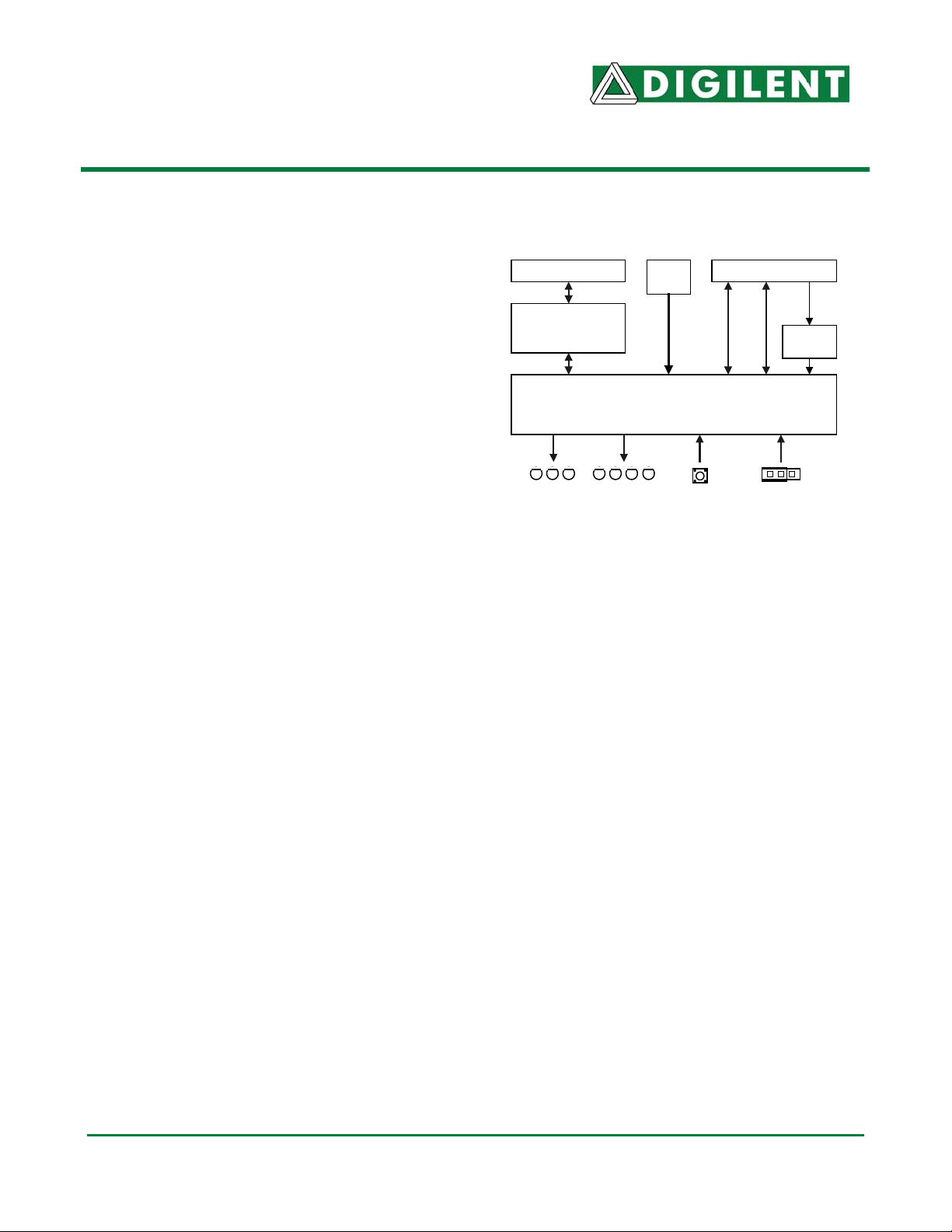
RJ-45 Connector
Transformer 1:1.41
(Transformers, Inc
XF2006CE)
Clock
(4.8MHz)
Expansion Connector
3.3V
2.5VDC
JTAG
Module Bus
regulator
The Ethernet module is built around the
UBICOM IP2022
Ubicom IP2022 chip that provides both a
media access controller (MAC) and physical
interface (PHY). The Ubicom chip drives the
four JTAG programming signals, and it also
communicates with the system board via a 14signal interface modeled after the “Enhanced
Parallel Port” (EPP) protocol. Firmware in the
Ubicom chip works with Digilent’s PC-based
3 User
LEDs
Figure 1. Ethernet Module Block Diagram
4 Status
LEDs
Pushbutton
1 jumper
(config reset)
Adept software to coordinate JTAG
programming and user data transfers.
For JTAG programming, the Digilent Adept
software tools can transfer .bit or .svf files
directly to the Ubicom chip, where the resident
firmware then drives the JTAG chain as
required. See the Digilent Adept Reference
Manual for more information. Both the Adept
software and reference manual are available
for download from the Digilent website.
For user data transfers, Digilent provides a
DLL, API, the required Windows drivers, and a
VHDL reference design (for inclusion in the
system board). The DLL, API, and drivers can
be downloaded and installed as a part of the
Digilent Adept software available at the Digilent
website. The VHDL reference design is
available as a separate download. See the
Digilent Port Communications Reference
Manual, the Digilent Parallel Interface Model
Reference Manual, and the VHDL source file
“dpimref.vhd” for more information).
The Digilent Ethernet Module is compatible
with all newer Digilent system boards
(including the S-3 Starter, Pegasus, D2SB, and
D2FT boards). It can also be used with the
older D2 and D2E for user data transfers (but
not for programming – see the individual board
documentation for more information). The
module should generally be connected to the
A1, B1, or C1 expansion connector for proper
operation. The module can be connected at
other expansion connectors, but JTAG
programming will not be available.
In operation, it is recommended that the
system board be turned off prior to connecting
the Ethernet module.
UbiCom IP2022
The Ubicom IP2022 provides an “all in one”
10Mbit Ethernet connectivity solution that
includes a MAC, PHY, and processor. Digilent
has written firmware for the processor that
allows the Ubicom part to easily support JTAG
programming and user data transfers. Digilent
also supplies Windows DLLs, APIs, and drivers
that can be used in custom Windows
applications to transfer data between a system
board and an attached PC.
Copyright Digilent, Inc. All rights reserved 3 pages Doc: 500-029
Page 2

Ethernet Module Reference Manual
The firmware in the Ubicom chip can be
modified using the Ubicom UNIVDNET kit
available from Ubicom. Digilent does not offer
any independent method or user support for
modifying the firmware.
Module Initialization
Before the Ethernet Module can be used, it
must be associated with a unique ID tag so
that the Digilent Adept software can locate it.
The Adept software can locate a module using
any one of three ID tags: an alphanumeric
name; a MAC address; or an IP address.
Before the module can be connected to a
general network, it must also be assigned a
unique IP address. Digilent provides an
“Ethernet Administrator” tool as a part of the
Adept software that can be used to assign ID
tags, including an IP address (see the Digilent
Adept Reference Manual for more information).
The Ubicom chip is configured with a unique
MAC address during manufacturing. The MAC
address is printed on a sticker affixed to the
board. By default, DHCP service is enabled on
the module, so that IP addresses and a subnet
mask can be automatically assigned from a
DHCP server when the board is first attached
to a network. If a DHCP server is not available,
then the subnet mask and IP address stored in
the Ubicom part will be used. The default
subnet and IP settings are shown below. Note
these settings may not be suitable for a given
installation, and they may need to be changed
(using the Ethernet Administrator) before the
module can be used.
Default settings on the module are:
• Module ID (DModNet1)
• IP address (192.168.0.2)
• Subnet mask (255.255.255.0)
• Default Gateway (0.0.0.0)
• DHCP setting (enabled)
These default settings can be automatically
restored at any time by loading a shorting
Digilent, IncTM
www.digilentinc.com
block on the Configuration Reset Jumper (JP1)
and power-cycling the board.
If the Ethernet Module fails to respond, the IP
address and subnet mask may not be
compatible with the current subnet. In this
event, the Configuration Reset jumper should
be shorted to restore factory defaults.
Connecting to Module
After the Ethernet module has been initialized,
it is ready to be used by applications. To use
the module either for JTAG programming or
user data transfers, it must first be identified
within the Adept software. Modules are
identified by adding one or more of their ID
tags to a “Device Table” list. This list is
accessed through the “Communications
Module” dialog box in Adept Suite (see the
Digilent Adept Reference Manual for more
information). Once the module has been
identified, JTAG programming and user data
transfers can commence.
Application Software
Digilent provides a Software Development Kit
that contains the DLLs, APIs, and necessary
Windows drivers to allow users to create their
own application software to transfer data to a
system board over the Ethernet. Digilent also
provides two application programs that can be
used to transfer data. These applications,
called Export (used for JTAG programming)
and Transport (for user data transfers) are
available as a part of the Adept software. See
the Digilent Software Development Kit
Reference Manual and Digilent Adept
Reference Manual for more information on
these applications.
User I/O
The Ethernet Module contains several I/O
devices, including an “ID” pushbutton, a
configuration reset jumper, and three status
LEDs.
© Digilent, Inc. Page 2 of 2
Page 3

Ethernet Module Reference Manual
ID button
When this button is pressed, the Ethernet
Module sends a UDP broadcast containing all
of the current settings. This broadcast is
captured and displayed in the Communications
Modules dialog box (see Digilent Adept Suite
User’s Manual).
Configuration Jumper
The configuration jumper at JP1 will be
sampled by the firmware when the board is
powered on, and periodically thereafter. When
loaded, the firmware will reset all factory
defaults listed above. The jumper must be
removed before the module can be used.
Status LEDs
Lnk: High when a solid Ethernet connection
is made.
Act: High when the board is actively
responding to a command.
Col: High when a packet collision is
detected.
Other Useful Information
The following items are all available for free
download from the Digilent website.
Documents
• Digilent Adept Reference Manual
• Digilent Port Communications Reference
Manual
• Digilent Parallel Interface Model Reference
Manual
• Digilent JTAG Scan Reference Manual
Software
• Digilent Adept Suite
• Digilent Adept Software Developers Kit
Reference Designs
• VHDL source file “dpimref.vhd”
Digilent, IncTM
www.digilentinc.com
Pinout table
The table below provides the pin assignments
for the expansion connector.
Pin # Signal
1 TDI
2 TDO
3 TMS
4 TCK
5 INT
6 JTSEL
7 WAIT
8 RESET
9 /DSTB
10 WRITE
11 DB7
12 ASTB
13 DB5
14 DB6
15 DB3
16 DB4
17 DB1
18 DB2
19
20 DB0
21
22
23
24
25
26
27
28
29
30
31
32
33
34
35
36
37 VDD33
38
39 GND
40 VU
© Digilent, Inc. Page 3 of 3
 Loading...