

Page 1
DMC60C Reference Manual
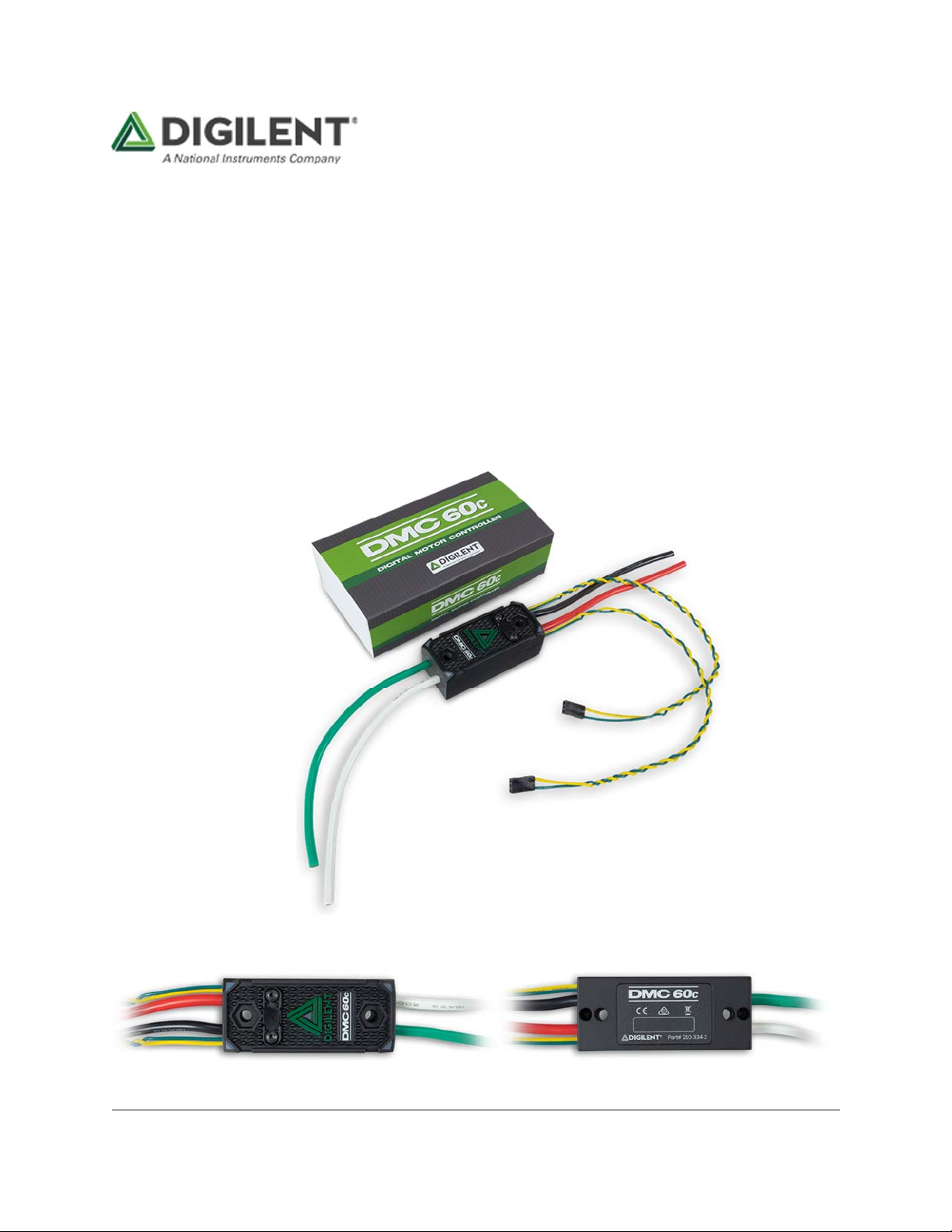
The DMC60C is the feature-packed, CAN-enabled successor to the DMC60. It is a powerful,
compact, FIRST Robotics Competition (FRC) approved motor controller designed for use with any
12-24V brushless DC motor. The DMC60C features an open loop PWM control mode, two internal
closed loop control modes (voltage compensation, current control), two external closed loop control
modes (position, velocity), and a follower control mode. These features are made available in
competition with an easy-to-use API, complete with examples, in C/C++, Java, and LabVIEW. The
DMC60C also features a web configuration utility that can be installed on any FRC configured
roboRIO. This configuration utility enables live configuration of several DMC60C parameters
including closed loop PID constants. This makes the DMC60C an ideal component in any robotics
application.
Page 2
Features
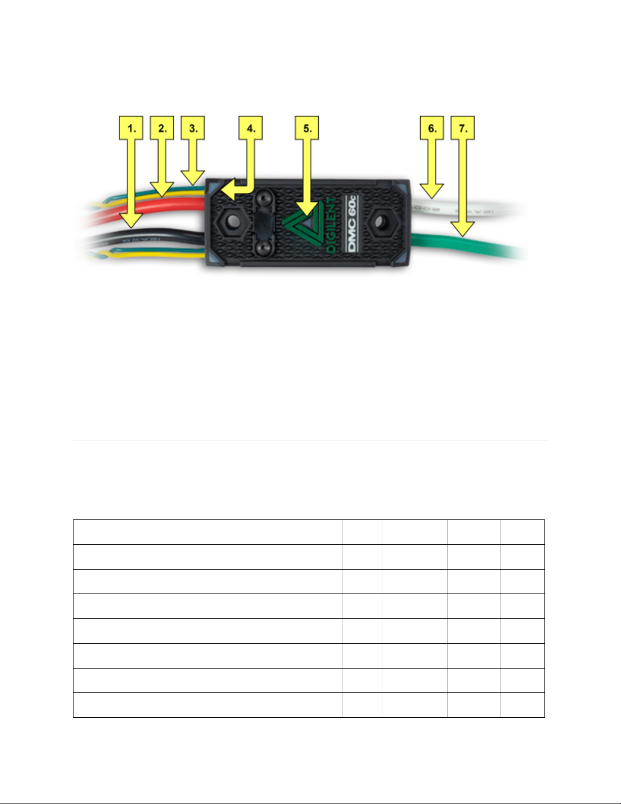
Callout Feature Description CalloutFeature Description
1 Input Ground (GND) 5 Brake/Coast CAL Button
2 Positive Input (V+) 6 Positive Output (M+)
3 Input Signal Cables (x2) 7 Output Ground (M-)
4 Status LEDs (x4)
Specifications
1Electrical
PARAMETER MIN NOMINAL MAX UNIT
Input Voltage 6 12 28 V
Continuous Current
Surge Current (2 seconds)
PWM Input Signal Pulse Width 0.6 1-2 2.4 ms
PWM Input Signal Period 2.9
PWM Input Signal Throttle Dead Band
100
4%
60 A
100 ms
A
PWM Input Signal Resolution
1
μs
Page 3
PARAMETER MIN NOMINAL MAX UNIT
PWM Input Signal Logic High Threshold 1.0
PWM Input Signal Logic Low Threshold
PWM Output Signal Frequency
2Mechanical
The DMC60C’s aluminum case is electrically isolated and may be mounted directly to a robot using
zip-ties or #8-32 screws. The case may become hot after pro-longed use in high current
applications. For optimum performance it is recommended that the DMC60C be mounted in a
location that allows airflow over the top of the case and around both sides of the case.
15625
0.4 V
V
Hz
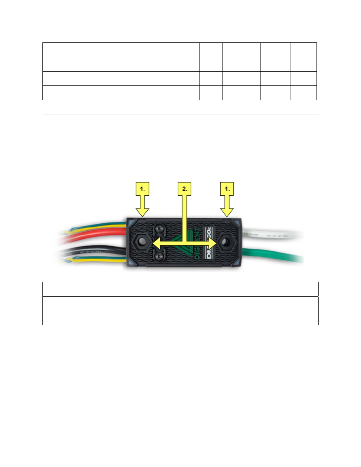
Callout Feature Description
1 Zip Tie Grooves
2 Mounting Holes and #8 Bolt/Nut Pocket Clearance
Mechanical Specifications Table
PARAMETER VALUE
DMC60C Length 2.76 in (70.0 mm)
DMC60C Width 1.18 in (30.0 mm)
DMC60C Height 1.00 in (25.4 mm)
Mounting Hole Spacing 2.00 in (50.8 mm)
Page 4

Functional Description
1PowerInputConnections
The DMC60C's black and red wires, labeled GND and V+ on the housing, respectively, are used to
carry input power from a chosen power source to the DMC60C. The black wire is to be connected to
the ground or negative terminal of the power source. The red wire is to be connected to the positive
terminal of the power source. When powering the DMC60C via a Power Distribution Panel (PDP),
this typically means that the DMC60C's red wire should be connected to the PDP's red terminal and
the DMC60C's black wire should be connected to the PDP's black terminal.
The DMC60C does not feature output short protection, and as such, shorting the output leads can
result in catastrophic failure. Therefore it is recommended that a 40 Amp breaker (or fuse) be placed
in line with the DMC60C's positive input lead (red wire).
The DMC60C does NOT include input reverse polarity protection. Reversing the polarity of the
inputs may result in permanent damage to the DMC60C.
2MotorOutputConnections
The DMC60C's green and white wires, labeled M- and M+ on the housing, respectively, are used to
carry a control signal from the DMC60C to a connected motor. The green wire is to be connected to
the negative lead of the motor. The white wire is to be connected to the positive lead of the motor.
The stall current associated with the motor may be very high. Therefore it is recommended that
these connections be made through crimped connectors or by soldering the leads directly together.
If the DMC60C output leads are not long enough to reach the motor then they may be extended. It is
recommended that 12 AWG (or thicker) stranded wire be used and that the wires be soldered
directly together.
3InputSignalCableConnections
The DMC60C can either be controlled by CAN signals applied on the input signal cables, or by PWM
input signals applied via one of the two input signal cables. Usage of the CAN protocol to control the
DMC60C is outside of the scope of this manual. Take a look at one of the guides on the DMC60C
Resource Center for more information on how to use the CAN protocol to control the DMC60C.
The DMC60C continually measures the positive pulse width of the PWM Input Signal applied to the
Input Signal Cable and maps it to an output voltage, or duty cycle. By default, a positive pulse width
of 1.0 milliseconds corresponds to 100% duty cycle in the reverse direction (current flow from M- to
M+), a positive pulse width of 2.0 milliseconds corresponds to 100% duty cycle in the forward
direction (current flow from M+ to M-), and a positive pulse width of 1.5 milliseconds (+/- 4%)
Page 5
corresponds to neutral. When a neutral pulse width is detected, the present Brake/Coast setting is
applied to the output. The DMC60C expects the PWM Input Signal to have an input period between
2.9 and 100 milliseconds. The allows te update rate to be as high as 344 Hz or as low as 10 Hz.
The DMC60C's Input Signal Cable features a 0.1“ pitch 3-pin female header that is compatible with
most RC / PWM Servo Controllers, allowing the DMC60C to be readily wired directly to those
devices. The Input Signal Cable consists of two wires, the signal wire (yellow), and the ground wire
(green).
4MotorControllerLEDs
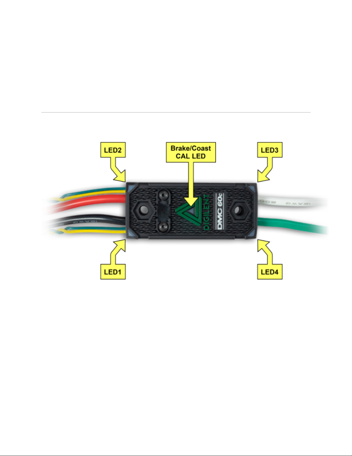
Figure 4.1 DMC60C LED Label Callout
The DMC60C contains four RGB (Red, Green, and Blue) LEDs and one Brake/Coast CAL LED. The
four RGB LEDs are located in the corners and are used to indicate status during normal operation,
as well as when a fault occurs. The Brake/Coast CAL LED is located in the center of the triangle,
which is located at the center of the housing, and is used to indicate the current Brake/Coast setting.
When the center LED is off, the device is operating in coast mode. When the center LED is
illuminated, the device is operating in brake mode. The Brake/Coast mode can be toggled by
pressing down on the center of the triangle, and then releasing the button.
At power-on, the RGB LEDs illuminate Blue, continually getting brighter. This lasts for approximately
five seconds. During this time, the motor controller will not respond to an input signal, nor will the
output drivers be enabled. After the initial power-on has completed, the device begins normal
operation and what gets displayed on the RGB LEDs is a function of the input signal being applied,
as well as the current fault state. Assuming that no faults have occurred, the RGB LEDs function as
follows:
Page 6

Table 4.1 LED Patterns in PWM Operating Mode
A
A
A
A
A
Servo Input Signal Applied LED State
No Input Signal or Invalid Input Pulse
Width
Neutral Input Pulse Width
Positive Input Pulse Width
Negative Input Pulse Width
Table 4.2 LED Patterns in CAN Operating Mode
lternate between top (LED1 and LED2) and bottom (LED3
and LED4) LEDs being illuminated Red and Off.
ll 4 LEDs illuminated Orange.
LEDs blink Green in a clockwise circular pattern (LED1 →
LED2 → LED3 → LED4 → LED1). The LED update rate is
proportional to the duty cycle of the output and increases
with increased duty cycle. At 100% duty cycle, all 4 LEDs
are illuminated Green.
LEDs blink Red in a counter-clockwise circular pattern
(LED1 → LED4 → LED3 → LED2 → LED1). The LED
update rate is proportional to the duty cycle of the output
and increases with increased duty cycle. At 100% duty
cycle, all 4 LEDs are illuminated Red.
CAN Bus Control State LED State
No Input Signal or CAN bus error
detected
No CAN Control Frame received within
the last 100ms or the last control frame
specified modeNoDrive (Output
Disabled)
Valid CAN Control Frame received
within the last 100ms. The specified
control mode resulted in a Neutral Duty
Cycle being applied to Motor Output
Valid CAN Control Frame received
within the last 100ms. The specified
control mode resulted in a Positive Duty
Cycle being Motor Output
lternate between top (LED1 and LED2) and bottom (LED3
and LED4) LEDs being illuminated Red and Off.
lternate between top (LED1 and LED2) and bottom (LED3
and LED4) LEDs being illuminated Orange and Off.
ll 4 LEDs illuminated solid Orange.
LEDs blink Green in a clockwise circular pattern (LED1 →
LED2 → LED3 → LED4 → LED1). The LED update rate is
proportional to the duty cycle of the output and increases
with increased duty cycle. At 100% duty cycle, all 4 LEDs
are illuminated Green.
Page 7

Valid CAN Control Frame received
within the last 100ms. The specified
control mode resulted in a Negative
Duty Cycle being Motor Output
LEDs blink Red in a counter-clockwise circular pattern
(LED1 → LED4 → LED3 → LED2 → LED1). The LED
update rate is proportional to the duty cycle of the output
and increases with increased duty cycle. At 100% duty
cycle, all 4 LEDs are illuminated Red.
5Brake/CoastMode
The DMC60C's response when a neutral duty cycle is applied to the output depends on the
Brake/Coast setting. When the DMC60C is configured for Brake Mode, the M+ and M- leads are
internally shorted when a neutral duty cycle is applied to the output, which causes an attached motor
to resist rotation. If an attached motor is spinning, then its speed decreases at a much quicker rate
than it would if the M+ and M- leads were allowed to float. When configured for Coast Mode, the M+
and M- leads float when a neutral duty cycle is applied to the output.
The current Brake/Coast setting is displayed by the Brake/Coast CAL LED, which is in the center of
the triangle located at the center of the housing. When the device is operating in Brake Mode, the
LED is illuminated Red. When the device is operating in Coast Mode, the LED is off. The
Brake/Coast setting can be toggled by pressing down on the center of the triangle, then releasing
the button.
The Brake/Coast setting is stored in non-volatile memory and is re-stored automatically after power
cycles.
When the DMC60C is connected to a CAN bus the Brake/Coast setting may be overridden by the
CAN control frame. When the Brake/Coast override is active the Brake/Coast CAL LED is overridden
to display the setting specified by the CAN control frame. During this time the DMC60C employs the
Brake/Coast mode that is specified in the CAN frame when applying the neutral duty cycle to the
output.
6InputSignalCalibration
The DMC60C accepts PWM input signals with a positive pulse width between 0.6 and 2.4
milliseconds. Due to variations in controllers, it may be necessary to adjust, or calibrate, the pulse
widths that correspond to the maximum forward and reverse duty cycles, as well as the neutral input.
To perform calibration, follow these steps:
1. Press and hold the Brake/Coast CAL button. After approximately 5 seconds, the top and
bottom LEDs will begin to alternate between Blue and Off. This indicates that calibration has
started.
2. While continuing to hold the button, use the controller to move between full forward and
full reverse (perhaps by moving a joystick), making sure to reach both extremes. This may
be repeated more than once, but there is no required minimum.
Page 8

3. Return the controller to neutral (return the joystick to the neutral position).
4. Release the Brake/Coast CAL button.
5. If calibration was successful, then the top and bottom LEDs will quickly alternate between
Green and Off and the new calibration constants will be stored in non-volatile memory. If
calibration failed, then the top and bottom LEDs will quickly alternate between Red and Off
and the device will continue to operate using the existing calibration constants.
Note: Calibration may only be performed while a servo input signal is present.
To restore default calibration:
1. Disconnect the power source from the DMC60C.
2. Hold the Brake/Coast CAL button down.
3. While continuing to hold the button, apply power to the DMC60C.
4. Continue holding down the button until the top and bottom LEDs alternate quickly between
Green and Off.
5. Release the Brake/Coast CAL button.
Note: This will also restore all DMC60C settings to their factory default state.
7InternalTemperatureMonitoringandOverTemperatureProtection
The DMC60C features an onboard thermistor, which allows the temperature of the circuit board to
be continuously monitored. When the motor controller detects that the temperature of the circuit
board has exceeded 70°C it will begin to decrease the duty cycle of the output. Additionally, the color
of the LED indicators will be changed to Cyan (forward) or Fuchsia (reverse) to indicate that the
device is operating in reduced duty cycle mode. As the temperature continues to rise, the duty cycle
will be further reduced at a rate of approximately 2.85% per degree C until the temperature of the
PCB exceeds 100°C, at which point the output duty cycle will be set to 0% and an over temperature
fault is signaled. The motor controller will continue to operate with a decreased duty cycle until the
temperature of the PCB falls below 70°C, at which point, it will resume outputting the duty cycle that
corresponds to the input signal.
8InputVoltageMonitoringandUnderVoltageProtection
The DMC60C continuously monitors the input voltage. If the input voltage falls below 5.75 Volts (+/2%) for 5 or more seconds, then the output duty cycle will be set to 0% and an under voltage fault is
signaled. The output will remain disabled until the fault is cleared (3 seconds), at which point it may
be re-enabled if the under-voltage condition is no longer present.
Page 9
9FaultIndicators
When a fault condition is detected, the output duty cycle is reduced to 0% and a fault is signaled.
The output then remains disabled for 3 seconds. During this time the onboard LEDs (LED1-4) are
used to indicate the fault condition. The fault condition is indicated by toggling between the top
(LED1 and LED2) and bottom (LED3 and LED4) LEDs being illuminated Red and off. The color of
the bottom LEDs depends on which faults are presently active. The table below describes how the
color of the bottom LEDs maps to the presently active faults.
Table 9.1 Fault Indicator LED Colors
Color Over Temperature Under Voltage
Green Present Not Present
Blue Not Present Present
Cyan / Aqua Present Present
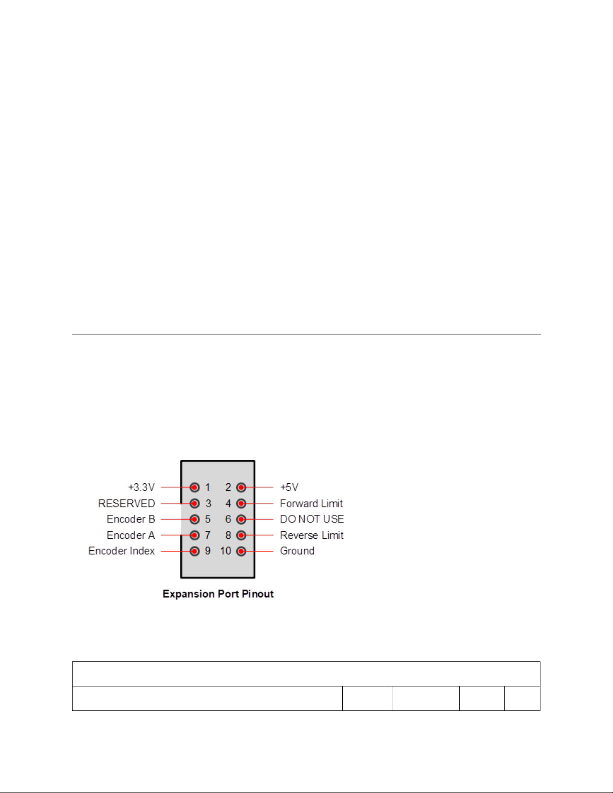
10ExpansionConnector
The DMC60C includes a 10-pin (2 x 5, 0.050” pitch) expansion port that allows sensors to be directly
attached to the controller. Presently it supports direct attachment of limit switches and quadrature
encoders. The figure below shows the pinout. Please note that any sensor attached to the expansion
port should be powered through pin 1 (+3.3V) and/or pin 2 (+5V) and should not be powered by an
external voltage supply.
Figure 10.1 DMC60C Expansion Port Pinout
10.1ExpansionPortElectricalSpecifications
Table 10.1.1 Expansion Port Electrical Specifications
PARAMETER MIN NOMINAL MAX UNIT
Page 10

+3.3V Supply Voltage 3.135 3.3 3.465 V
A
A
+3.3V Supply Current
0.050
+5V Supply Voltage 4.75 5.0 5.25 V
+5V Supply Current
Digital Input Signal Logic High Threshold1) (Encoder
A, B, Index, Fwd/Rev Limit)
Digital Input Signal Logic Low Threshold (Encoder A,
B, Index, Fwd/Rev Limit)
1)
All expansion port digital input pins tolerate input voltages up to 5.5V. Each of these pins is
2.64
0
0.100
5.5 V
0.66 V
clamped to the 3.3V supply through a 200 ohm resistor and a Schottky diode
11LimitSwitches
The DMC60C expansion port includes pins for attaching both forward and reverse limit switches.
These input pins can be individually configured to interface with a normally open or normally closed
switch using Digilent’s web-based configuration utility on the RoboRio or by sending the appropriate
CAN frame on the CAN bus. Additionally, the enable/disable state of the limit switch inputs can be
overridden by the CAN control frame.
By default, both the forward and reverse limit switch inputs are enabled and configured to interface
with normally open switches. When a limit switch is active the DMC60C will not allow the motor
output to be driven in the associated direction. Any attempt to drive the output in the direction of an
active limit switch will result in the neutral duty cycle being applied to the H-Bridge.
The onboard Microcontroller uses internal pull-ups on both pins, and as a result, no external pull-ups
are required. The diagrams that follow show how to wire switches to the forward and reverse limit
switch inputs.
Page 11

Figure 11.1
Figure 11.2
Figure 11.3
Page 12

Figure 11.4
12QuadratureEncoderInput
The DMC60C can perform closed loop velocity and closed loop position control. Velocity and
position measurements are made using a quadrature encoder. A quadrature encoder may be
attached to the Encoder A, Encoder B, and Encoder Index (optional) pins of the DMC60C expansion
port. Please note that the encoder should be powered by the +3.3V or +5V pins of the expansion
port, and that these pins should never be connected to each other.
Figure 12.1 DMC60C Quadrature Encoder Connection
Table 12.1 Quadrature Encoder Input Specifications
PARAMETER MAXIMUM
Quadrature Encoder Counts per Revolution 78,643,200 / Max RPM
Quadrature Encoder RPM 78,643,200 / Max Counts Per Revolution
Page 13

13QuadratureEncoderIndex
The DMC60C expansion port includes a pin (Encoder Index) for attaching a digital sensor or a
switch to automatically clear the quadrature encoder’s position count. The onboard Microcontroller
uses an internal pull-up, which makes it possible to attach a switch directly without the need for an
external pull-up.
The DMC60C can be configured to clear the position count in response to a rising or falling (default)
edge on the Encoder Index pin. By default, this functionality is disabled, and any input applied to the
Encoder Index pin is ignored by the DMC60C.
The DMC60C may also be configured to clear the position count based on the logic level of a signal
applied to the Forward Limit or Reverse Limit pins of the expansion connector. By default, this
functionality is disabled. The active state required to clear the position count is dependent on the
configuration of the associated limit switch input. For example, if the Forward Limit switch is
configured as a normally open switch then a logic ‘0’ on the Forward Limit pin will cause the position
count to be cleared when this functionality is enabled. If the Forward Limit switch is configured as a
normally closed switch, then a logic ‘1’ on the Forward Limit pin causes the position count to be
cleared when this functionality enabled. Please note that the position count continues to be cleared
for as long as the associated pin remains driven to the active state.
The figures below show how to attach a switch to the Encoder Index pin of the expansion port.
Figure 13.1
Figure 13.2
Page 14

14RestoringFactoryDefaultConnections
Perform the following steps to restore factory default settings:
1. Disconnect the power source from the DMC60C.
2. Hold the Brake / CAL button down.
3. While continuing to hold the button, apply power to the DMC60C.
4. Continue holding down the button until the top and bottom LEDs alternate quickly between
Green and Off.
5. Release the Brake / CAL button.
The manufacture date string, hardware revision number string, and serial number string will be
retained. All other non-volatile configuration variables, including the CAN bus device number, are
reset to their factory default stat
https://reference.digilentinc.com/dmc‐60c/hardware‐reference‐manual/2‐4‐19
 Loading...