


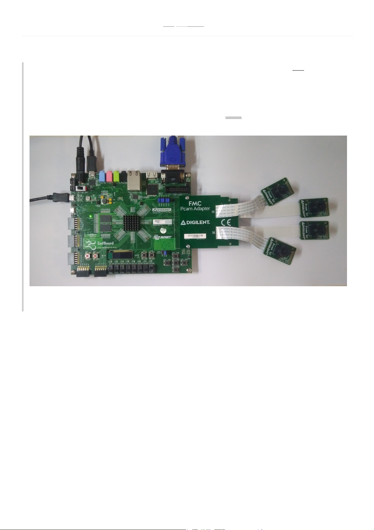
Fig1.The demo in action - displaying all four Pcam 5C data.
This project demonstrates the usage of the FMC Pcam Adapter as an interface from one up to four different Pcam cameras
and the ZedBoard platform. The Video Stream from each different camera is getting in through the MIPI/FMC
connectors and out through the carrier VGA port. For errors and feed-back messages, an uart interface is present.
Not Used U
512MBDDR3 (128M x 32)
256 Mb QSPI Flash X
USB-JTAG
10/100/1G Ethernet X
ZedBoard FMC Pcam Adapter One to Four Camera
Demo
Overview
Description
Features Used

Basic familiarity with Vivado & SDK
This experience can be found by walking through our “Getting Started with Vivado” guide
ZedBoard board
12V voltage supply
2 Micro-USB cables. One for programming and the other one for the uart interface
1 VGA cable
From 1 to 4 Pcam-5C cameras
VGA monitor
Vivado Design Suite & Xilinx SDK 2018.2
Version 2018.2 is the only one used for testing the project
Not Used U
USB OTG 2.0 X
SD Card X
USB 2.0 FS USB-UART bridge
5 Digilent Pmod™ compatible headers X
1 LPC FMC
1 AMS Header X
2 Reset Buttons (1 PS, 1 PL) X
7 Push Buttons (2 PS, 5 PL) X
8 dip/slide switches (PL) X
9 User LEDs X
HDMI Output X
VGA (12-bit Color)
128×32OLEDDisplay X
Audio, headphone, microphone X
Prerequisites
Skills
Hardware
Software
Downloads
ZedBoard FMC Pcam Adapter Project Repository –ZIPGIT Repo
Please follow the instructions that are listed in the chapter “DEMO” of the README file (checkhere). Keep in mind
that you have to export the hardware platform and the bitstream file before launching SDK. Return to this guide
when prompted to check for additional hardware requirements and setup.
Plug one end of the VGA cable into the VGA port of the ZedBoard and the other end into your VGA monitor.
Attach a USB micro cable between the J7 programming port and your computer. Also, attach a second USB micro
cable between J14 UART port and your computer. After this, attach an external 12V power supply. Finally, make sure
that VADJ is set to 3V3 and all the MIOs pins are connected to SIG andGND. This sets the primary boot mode to
JTAG.
Fig.2 Overall setup
Download and Launch the ZedBoard FMC Pcam-Adapter Demo

First, you have to make sure that all the Pcam connectors in which you want to insert the FFC cable are open. Pull the
black plastic tab on the edge of the connector out, away from the opening of the connector. This opens the connector,
as it can be seen in the first image bellow.
Insert the FFC with the contacts facing up, toward the Pcam 5C PCB. The blue side (without contacts exposed)
should be facing down on the Pcam side. Repeat the same procedure with the Pcam connector on the FMC Pcam
Adapter, as you can see in the image number 2.
Fig.3 First image shows the bottom of the FMC Pcam Adapter with the connectors left open, and the second image shows the FFC cable
with the contacts facing up
After this, please ensure the FFC is fully inserted, and press both sides of the black plastic tab back towards the rest of
the connector to latch the FFC in. Bellow you can see two cables which are fully inserted.
Repeat the same procedure with the camera C and D. But, this time the cables should go trough the two slots which
are present on the Adapter. If the cable has become disconnected from the Pcam 5C or the FMC Pcam Adapter,
please repeat the steps presented above.
Fig.4 Two properly connected cameras, and four properly connected cameras

Finally, after you connected all the cameras, you have to connect the FMC connector to the ZedBoard. To ensure that
it stays firmly in place you should use one or two bolts as you can see in the image bellow.
Fig.5 Final setup
To see the UART communication channel, open a terminal program on your computer set to 115200 baud rate, 8 data
bits, no parity bit and 1 stop bit. On startup, the ZedBoard will show feed-back and error messages on the serial
console.
Fig.6 Serial terminal that shows the Init. message

If a camera is unconnected you will receive an warning message. The program will skip this warning and will start to
initialize the rest of the cameras.
Fig.7 Serial terminal that shows the Init. message and the incorrectly init of camera A
As I said before, if a camera is unconnected the project will continue the initialization of the rest of the cameras, and
the VGA monitor will output a gray image, signaling the lack of video data in the DDR memory.
Fig.8 Output VGA image with the camera A disconnected
 Loading...