

Page 1
You are here:: Digilent Documentation / Reference / Instrumentation / Analog Discovery Studio
/ Breadboard Canvas Reference Manual
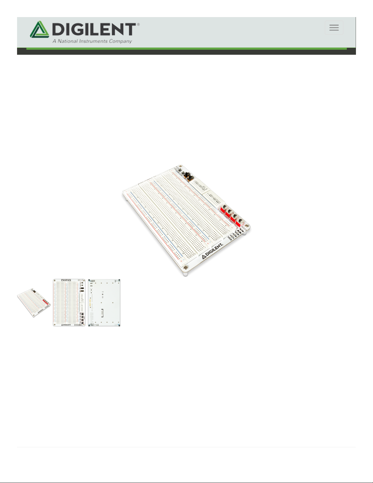
The Breadboard Canvas is a replaceable and removable prototyping surface for the Analog Discovery Studio. The bulk of
the Breadboard Canvas consists of 2 regular sized breadboards and three power rails. At the top of the board, two small
breadboards contain the power access pins for the power supplies, and pin breakouts for the included I/O. Two switches,
LEDs, and buttons are integrated into the Breadboard Canvas for convenience. The power supply access pins can be
switched on and off via the power supply switches, and the status is indicated by the power indicator LEDs. The
Breadboard Canvas is included with the Analog Discovery Studio.
The Breadboard Canvas is designed to connect to the Analog Discovery Studio via standoffs. Magnets are located within
each of the holes that the standoffs slot into in order to hold the Canvas in place. The Breadboard Canvas can be removed
from the Analog Discovery Studio and swapped out with other canvases.
Warning! Do not swap out Canvases while the Analog Discovery Studio is turned on.
Breadboard Canvas Reference Manual
Mechanical Design
Digilent uses cookies to ensure you get the best experience on our websites. By using our site you agree to our use of cookies.
Got it!
Learn More
Page 2

The Analog Discovery Studio Breadboard Canvas has two regular-size breadboards and three power rails mounted to the
canvas surface.
Each of the Analog Discovery Studio's power supplies, both variable and fixed, are connected to the canvas, accessible
via the power supplies breadboard.
The power access pins for the variable supplies, labeled V+ and V-, are connected to the Analog Discovery Studio's
programmable power supplies. They can be programmed to voltage levels from 1 to 5V (V+) and -1 to -5V (V-) through
the use of WaveForms' Power Supplies instrument.
Four fixed supplies are available, +12V, -12V, 5.0V, and 3.3V.
The power access pins can be enabled or disabled via the set of four switches adjacent to the power supplies breadboard.
Green status LEDs, associated with each supply, turn on when power is available on that pin (when the supply is enabled,
and the ADS is turned on).
Since each power supply is sourced directly from the Analog Discovery Studio, the minimum and maximum current and
power available for each supply depends on the Analog Discovery Studio's specifications. See the Analog Discovery
Studio Specifications for more information.
The Analog Discovery Studio Breadboard Canvas features a variety of common components which can be used within a
circuit under test.
Each of the components described in this section is accessed via pins on the small breadboard adjacent to SW2, referred
to as the Built-in IO Breadboard.
Two switches are available on the Breadboard Canvas. When switched to the “On” position (switched away from the
breadboard surface), they provide a connection between the 5.0V power rail and the corresponding pins (SW1, SW2) on
the Built-in I/O Breadboard. The 5.0V power rail must be enabled to use the buttons.
A circuit diagram detailing how the switches are connected to the Built-in I/O Breadboard can be seen below.
Two user buttons are also available. When pressed, they provide a connection between the 5.0V power rail and the
corresponding pins (BTN1, BTN2) on the Built-in I/O Breadboard. The 5.0V power rail must be enabled to use the buttons.
A circuit diagram detailing how the buttons are connected to the Built-in I/O Breadboard can be seen below.
Breadboards
Power Supplies
Built-in Components
User Switches
User Buttons
Page 3
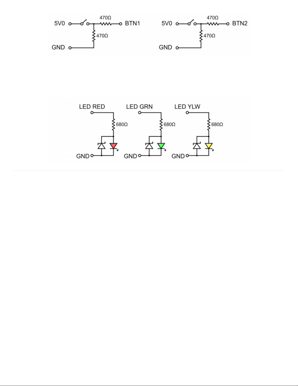
Three light emitting diodes, each of a different color, red, green, and yellow, are available on the Breadboard Canvas.
These LEDs can be controlled by providing power to the corresponding pin on the Built-in I/O Breadboard.
A circuit diagram detailing how the LEDs are connected to the Built-in I/O Breadboard can be seen below.
User LEDs
 Loading...