

Page 1
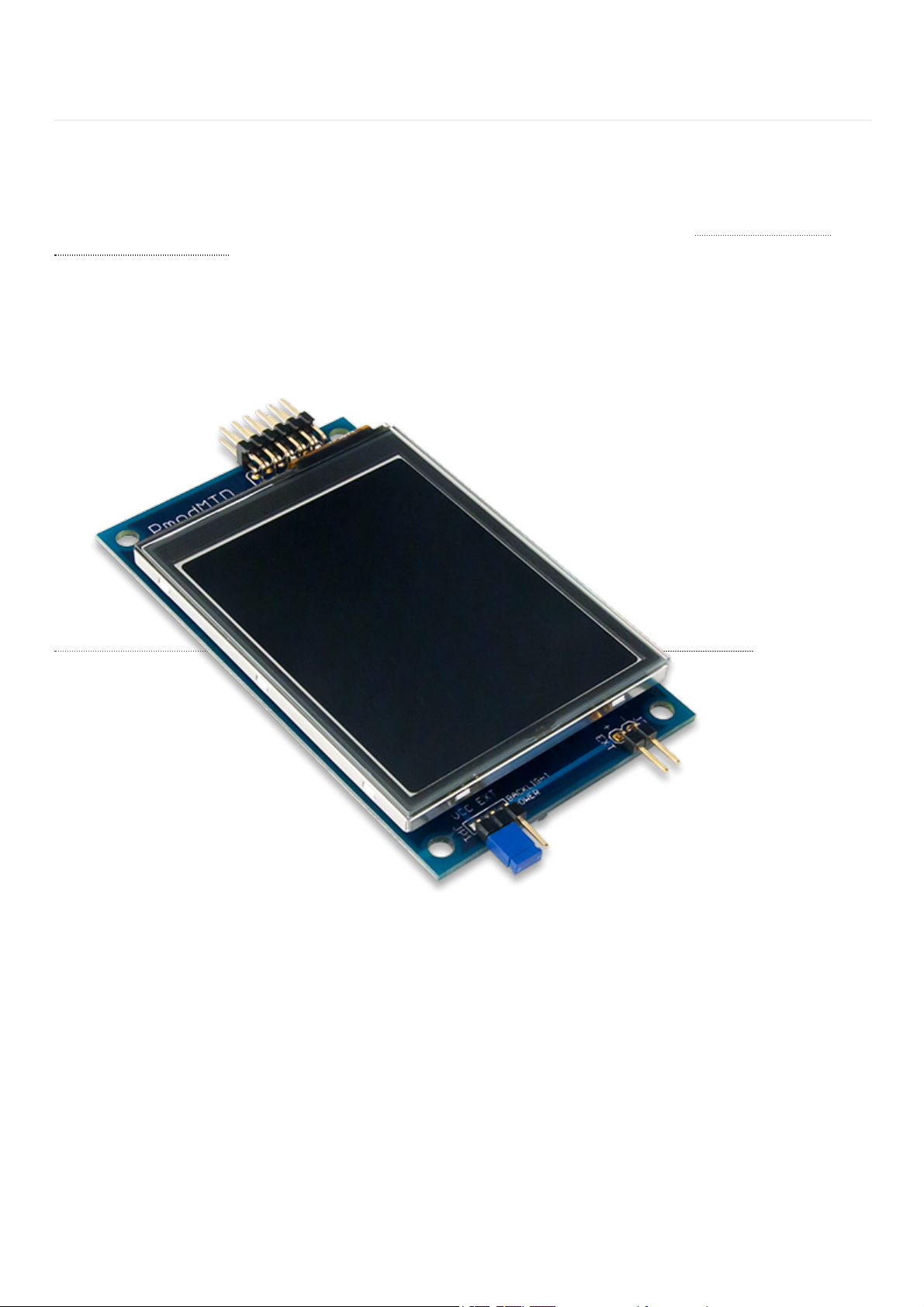
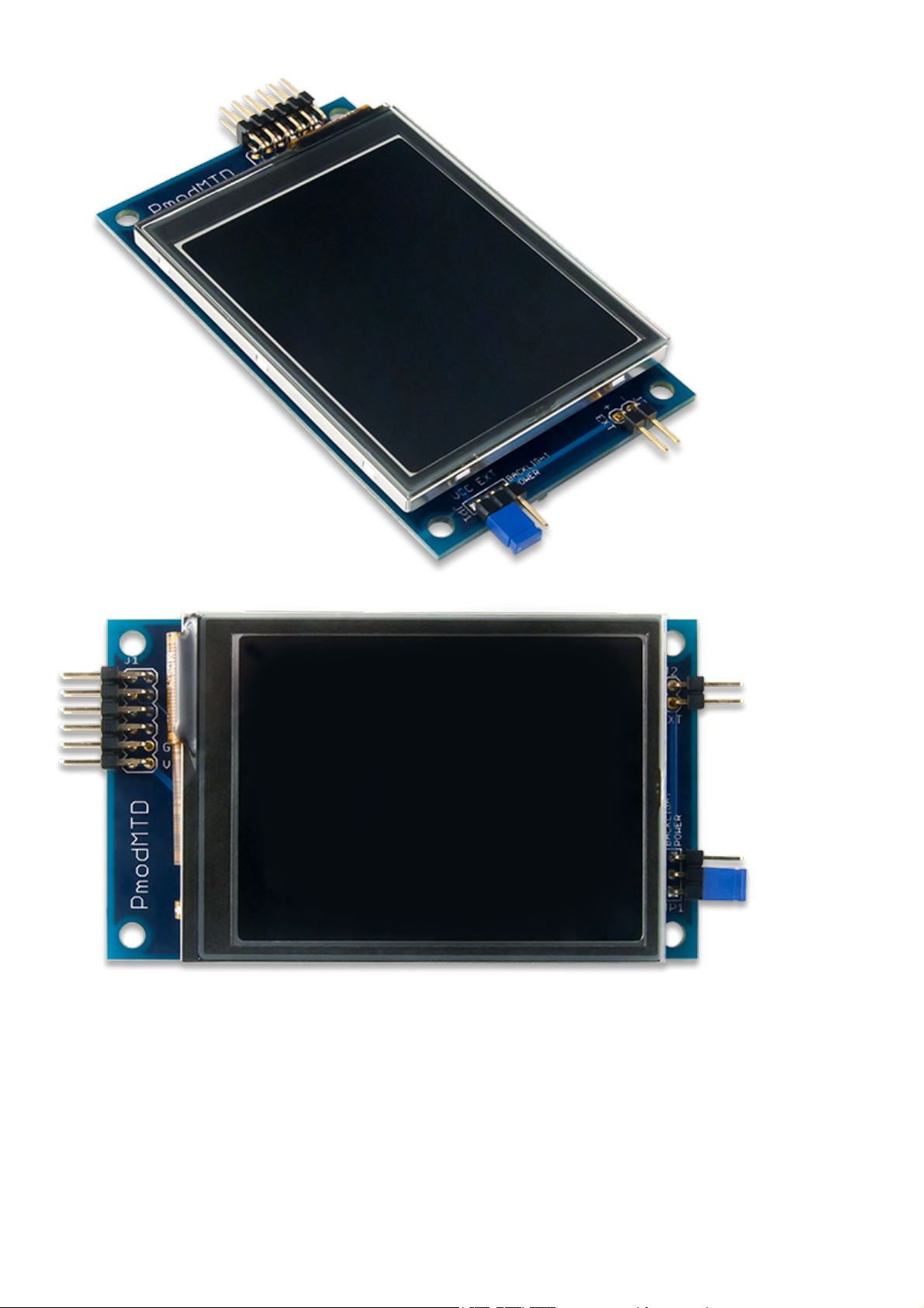
The Digilent Pmod MTDS (Revision A) is a gorgeous 2.8“ touchscreen display with a powerful on-board microcontroller
that performs graphics processing tasks. The display is a capacitive touchscreen with QVGA resolution (320×240) and 2
finger multi-touch support.
The most compelling aspect of the Pmod MTDS is the programming experience provided by itsMulti-Touch Display
System (MTDS) Firmwareand the associated libraries. These allow you to design sleek, stylish user interfaces very quickly
and with very little code. The timing dependent tasks are handled by the firmware, so integrating the display into existing
projects is also a snap. Some of the key functionality provided by the libraries include the ability to draw basic shapes and
text, draw images stored on microSD with binary transparency, draw buttons and easily check if they have been pressed,
and check the status and location of the user's two fingers. The libraries are supported in Arduino IDE and Xilinx SDK,
and have been tested with Ardiuno, chipKIT and Arty host boards.
Pmod MTDS Reference Manual
Page 2
Page 3

Page 4
Pmod MTDS PDF
2.8” Display with QVGA resolution (320×240)
2 Finger Capacitive touch panel
Powerful PIC32MZ Microcontroller
Multi-Touch Display System (MTDS) Firmware
Design a beautiful UI with only a few lines of code using libraries for Arduino IDE and Xilinx SDK
Follows the DigilentPmod Interface Specification 1.0, Type 2A (Expanded SPI)
Table 1. Pmod MTDS Specifications
* IfVCCis selected as the Backlight Power source then the minimum voltage is 2.7 V.
Parameter Min Typical Max
Pmod Power Supply Voltage (VCC) 2.2* 3.3 5.5
Optional External Power Supply Voltage (VEXT) 2.7 5.0 6
Header J1 Header J2 (External Backlight Po
Pin Signal Description Pin Signal Description Pin Signal Description
1 CS Chip Select 7 NC Not
Connected
1 VEXT External Power Suppl
Connection
Download This Reference Manual
Features
Specifications
Pinout Table Diagram
Page 5
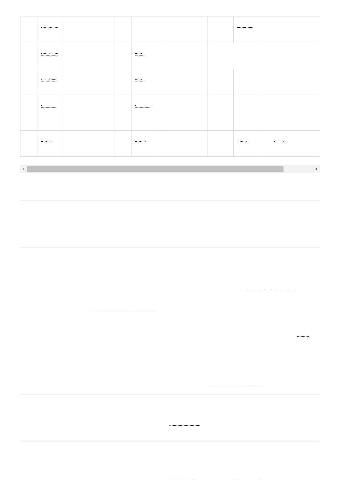
Table 2. Pmod MTDS Pinout
* Pins 9 and 10 of J1 are attached to the PIC32, but are not used by the firmware and should be treated as if they are not connected.
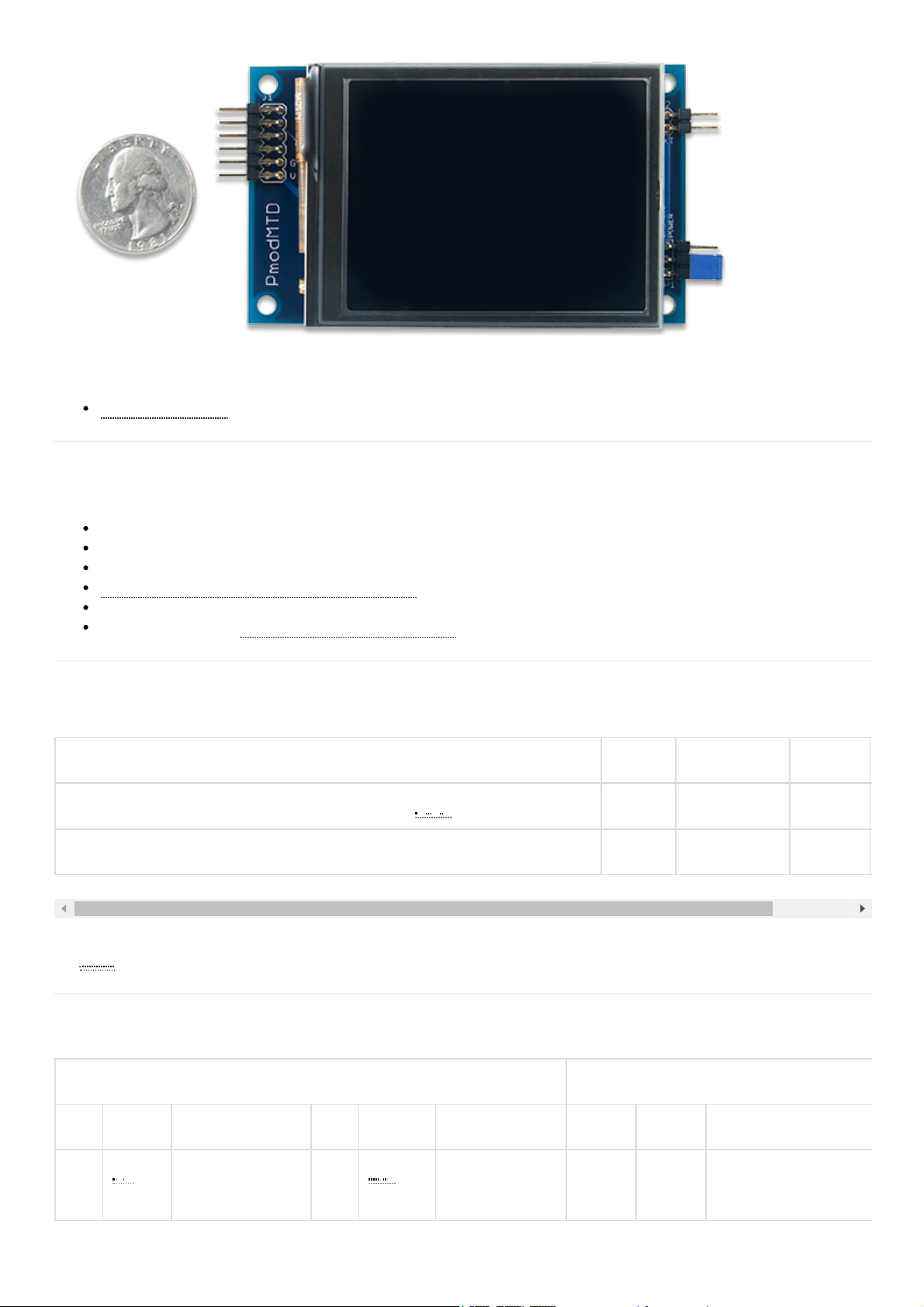
The pins on the pin header are spaced 100 mil apart. The PCB is 3.45 inches long on the sides parallel to the pins on the
pin header and 2.00 inches long on the sides perpendicular to the pin header.
The Pmod MTDS has an on-board PIC32MZ microncontroller that is running the MTDS firmware. To communicate with
the device, you must use the MTDS and MyDisp libraries available and documented on theMTDS resource center.
Arduino and chipKIT host boards should use the Arduino IDE libraries, and Xilinx FPGA or Zynq based host boards
should use the Pmod MTDS IP core and the libraries included with it. For information on downloading and using the
Pmod MTDS IP core see theUsing Pmod IPs Tutorial. After exporting to Xilinx SDK, follow the README.txt guide
included in the examples folder.
JP1 is used to select how to power the display's backlight. A single jumper should be loaded across 2 of the three pins in
order to select the power source. When the jumper is loaded across the bottom 2 pins the backlight is powered byVCCon
the Pmod connector, and when it is loaded across the top two pins the backlight is powered by an external power supply
attached to J2. This external power supply must meet the minimum and maximum voltage requirements outlined in the
Specifications table above.
The microSD connector allows the MTDS firmware to draw and save images to an attached microSD card. In order to
work properly, the microSD card must be formatted as FAT32. Image files should be saved as Windows Bitmap files
(.bmp). For more information see the MTDS documentation available on theMTDS resource center.
The Pmod MTDS communicates with the host board via theSPI protocol, however the implementation of this physical
interface is handled by the MTDS libraries and it is not necessary to understand the details for its use.
2 MOSI Master Out
Slave In
8 RESET Active-Low
Reset
2 GND Power Supply Ground
3 MISO Master In Slave
Out
9 NC* Not
Connected
Jumpers
4 SCLK Serial Clock 10 NC* Not
Connected
Name State Description
5 GND Power Supply
Ground
11 GND Power Supply
Ground
JP1 EXT Use External power su
attached to J2 to powe
Backlight
6 VCC Power Supply
(3.3V/5V)
12 VCC Power Supply
(3.3V/5V)
JP1 VCC UseVCCfrom Pmod
to power Backlight
Physical Dimensions
Functional Description
Serial Communication
Quick Usage
Page 6

To get started with the Pmod MTDS quickly, go to theMTDS resource centerand follow the instructions found there for
your host platform.
The schematics of the Pmod MTDS are availablehere.
More specific information about how to use the Pmod MTDS can be found at theMTDS resource center.
If you have any questions or comments about the Pmod MTDS, feel free to post them under the appropriate section
(“Add-on Boards”) of theDigilent Forum.
Additional Information
 Loading...