

Page 1
1300 Henley Court
Pullman, WA 99163
509.334.6306
www.digilentinc.com
PmodRS232™ Reference Manual
Revised April 15, 2015
This manual applies to the PmodRS232 rev. B
DOC#: 502-068
Copyright Digilent, Inc. All rights reserved.
Other product and company names mentioned may be trademarks of their respective owners.
Page 1 of 2
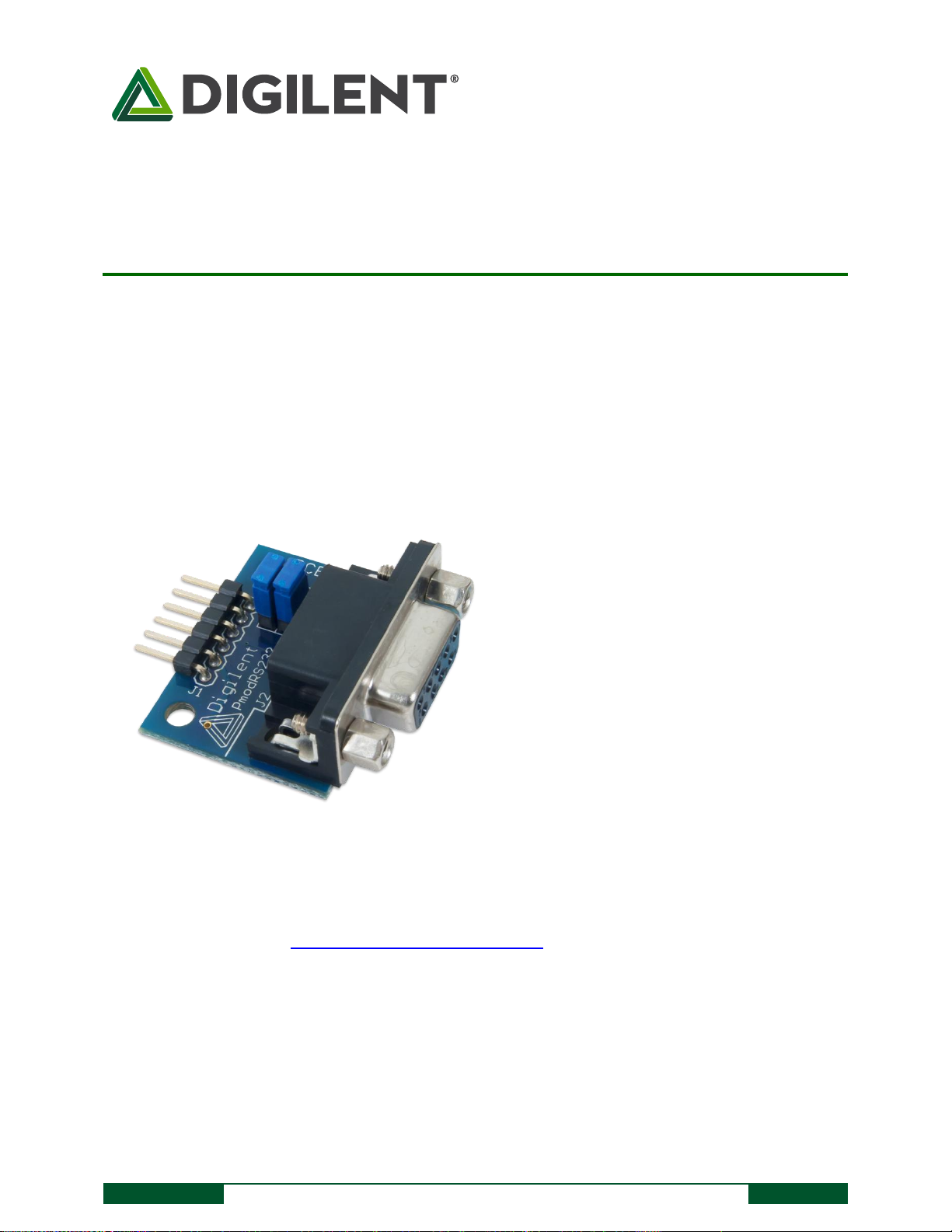
The PmodRS232.
A DB9 connector and 6-pin header.
Optional RTS and CTS handshaking
functions.
Converts between digital logic voltage levels
to RS232 voltage levels.
Features include:
Overview
The Digilent PmodRS232 converts between digital logic voltage levels to RS232 voltage levels. The RS232 module is
configured as a data communications equipment (DCE) device. It connects to data terminal equipment (DTE)
devices, such as the serial port on a PC, using a straight-through cable.
1 Functional Description
The PmodRS232 utilizes the Maxim Integrated MAX3232 transceiver to allow the system board to communicate
with UART compatible devices or other components that use a serial interface.
2 Interfacing with the Pmod
The PmodRS232 communicates with the host board via the UART protocol. The arrangement of the pins is the
the old UART communication style so that a crossover cable will be required if attaching this Pmod to one of the
dedicated UART Pmod headers on a Digilent system board.
Page 2
PmodRS232™ Reference Manual
Copyright Digilent, Inc. All rights reserved.
Other product and company names mentioned may be trademarks of their respective owners.
Page 2 of 2
JP1
JP2
Communication
Unloaded
Pins 1 and 2 are shorted together
3-wire communication
Pin 1 connected to pin 1 of JP2 and
pin 2 connected to pin 2 of JP2
Pin 1 connected to pin 1 of JP1 and
pin 2 connected to pin 2 of JP2
5-wire communication
Pin
Signal
Description
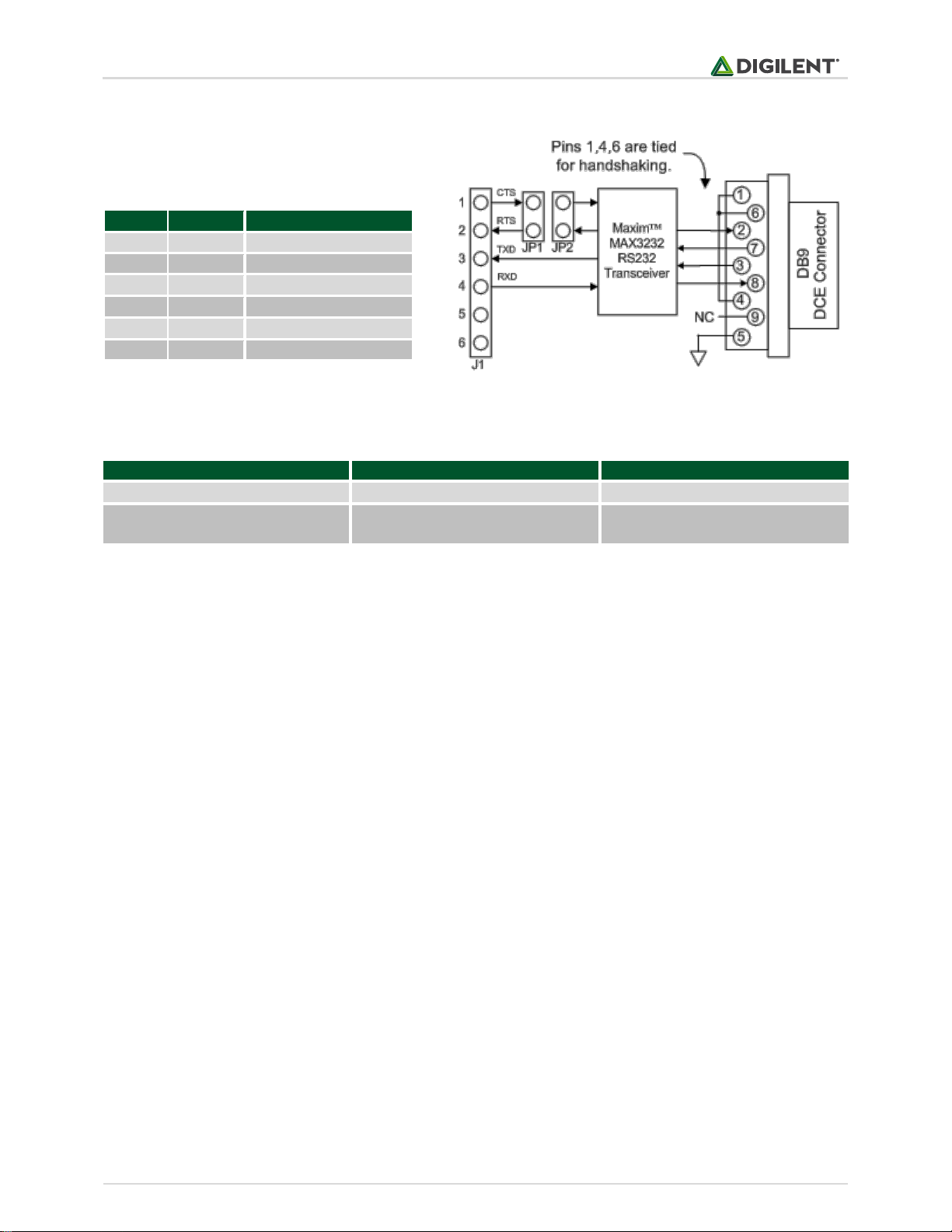
1
CTS
Clear to Send
2
RTS
Ready to Send
3
TXD
Transmit Data
4
RXD
Receive Data
5
GND
Power Supply Ground
6
VCC
Power Supply (3.3V/5V)
Figure 1. PmodRS232 block diagram.
Table 1. Connector J1 pin descriptions.
A pinout description table and diagram for the PmodRS232 are provided below:
Table 2. Jumper block settings.
There are two jumper blocks on the PmodRS232; JP1 and JP2. These jumper blocks allow the PmodRS232 to
communicate in either a 3-wire or 5-wire operation. When the jumper block on JP2 is loaded and the block on JP1
is unloaded, the on-board chip has its RTS and CTS lines tied together, indicating to the MAX3232 that it is free to
transfer data whenever it receives any and enabling 3-wire communication. JP1 must be unloaded in this
configuration to ensure that pins 1 and 2 on the Pmod header are not shorted together which could potentially
damage the system board.
5-wire communication requires that pin 1 of JP1 is connected to pin 1 of JP2, and that pin 2 of both JP1 and JP2 are
tied together as well, effectively allowing for CTS/RTS handshaking between the Pmod header and the on-board
chip. Both the fifth wire in this configuration and the third wire in the 3-wire communication is the ground signal
line.
Any external power applied to the PmodRS232 must be within 3V and 5.5V; however, it is recommended that
Pmod is operated at 3.3V.
3 Physical Dimensions
The pins on the pin header are spaced 100 mil apart. The PCB is 1 inch long on the sides parallel to the pins on the
pin header and 1.3 inches long on the sides perpendicular to the pins on the pin header. The DB9 connector adds
an additional 0.25 inches to the length of the PCB that is parallel to pins on the pin header.
 Loading...