

Page 1
DDiiggiilleenntt CCeerreess RReeffeerreennccee MMaannuuaal
Revision: August 11, 2005 246 East Main | Pullman, WA 99163
l
www.digilentinc.com
(509) 334 6306 Voice and Fax
TM
Overview
The Ceres board provides a ready -made
development platform for Digilent C-Mod
boards. It contains a 40-pin DIP socket to hold
C-Mods, and a collection of useful I/O devices
connected to the socket pins. The Ceres/CMod board combination makes an ideal
platform for students or engineers who want to
experiment with modern design technologies
and/or Xilinx CPLD devices. The Ceres board
can operate from a wall-plug power supply
(included), or up to 40 hours on two AA
batteries. Ceres features include:
• An user-settable oscillator (0.5Hz - 4KHz);
• 4-digit, high-bright seven-segment display;
• 4 debounced buttons and 8 slide switches;
• 8 LEDs in three different colors (red, green,
and yellow);
• 40-pin Dip format receptacle for use with
the C-Mod line of boards;
• 40-pin expansion connector capability.
• Attached C-Mod boards can be
programmed with JTAG3 cable.
The Ceres/C-Mod board makes an excellent
platform for introducing programmable
technologies in instructional lab settings. The
C-mod boards can host a wide range of
designs, from simple logic circuits to complex
state machines. The CPLDs use non-volatile
configuration memory, so designs can be
completed outside the lab and brought in for
evaluation. The Ceres/C-mod combination is
fully compatible with all versions of the Xilinx
CAD tools, including the free WebPack tools
available at the Xilinx website. When
purchased in combination, the Ceres/C-Mod
ships with a programming cable and a power
source, so designs can be implemented
immediately without the need for any additional
hardware.
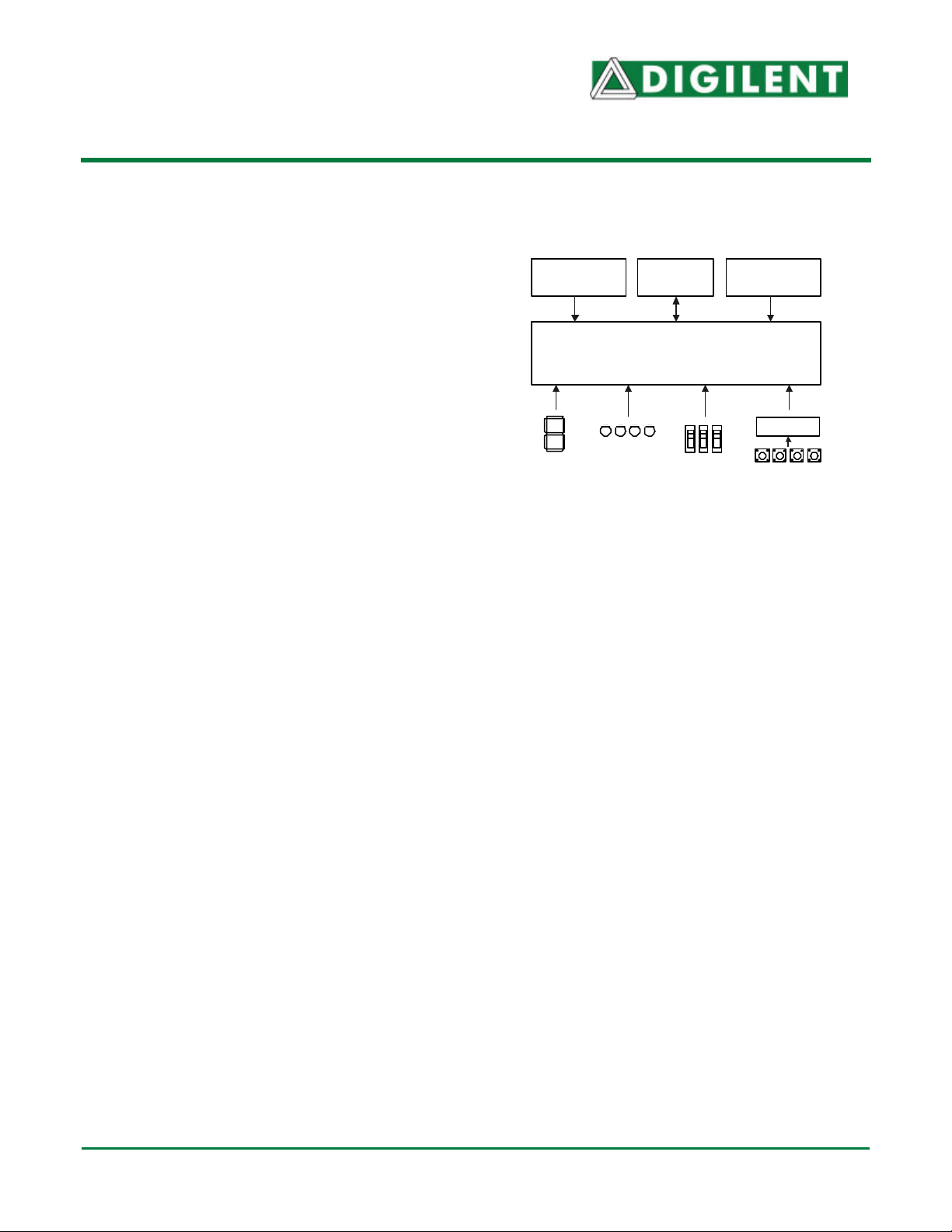
Power/Battery
Jack
Four 7-seg.
displays
Figure 1. Ceres Block Diagram
Expansion
Connector
C-Mod Board Socket
40-pin 600-mil DIP
8 LEDs
8 switches
Functional description
The Ceres board provides a power supply and
collections of I/O devices that can be used by
C-Mod boards. Ceres boards can host different
C-Mod boards, so designs can easily be
retargeted to different CPLD devices for
experimentation. Current C-Mod boards
include the C-Mod 95 (XC9572XL), the C-Mod
C2 (XC2C64), and the C-Mod XCR
(XCR3064XL).
The Ceres board can be powered from a wallplug power supply or from a 2AA battery pack.
A 40-pin expansion connector makes all DIP
connector signals available to external circuits.
Ceres/C-Mod JTAG Configuration
C-Mod boards contain a JTAG port for
programming, but the Ceres board does not.
The C-Mod JTAG port consists of a pattern of
six offset holes that are not normally loaded
with header pins. A row of 6 unattached
header pins can be inserted into the end of a
JTAG3 cable, and the other side of the header
can be inserted into the offset hole patterns.
Adjustable clock
(0.5Hz to 4KHz)
Debounce
4 buttons
© Digilent, Inc. 4 pages Doc: 502-048
Page 2
Ceres Reference Manual Digilent, Inc.
Once the C-Mod board is connected to the PC
via the JTAG cable, the configuration software
will automatically detect the CPLD. For more
information, see the “Configuration” section of
the C-Mod reference manual.
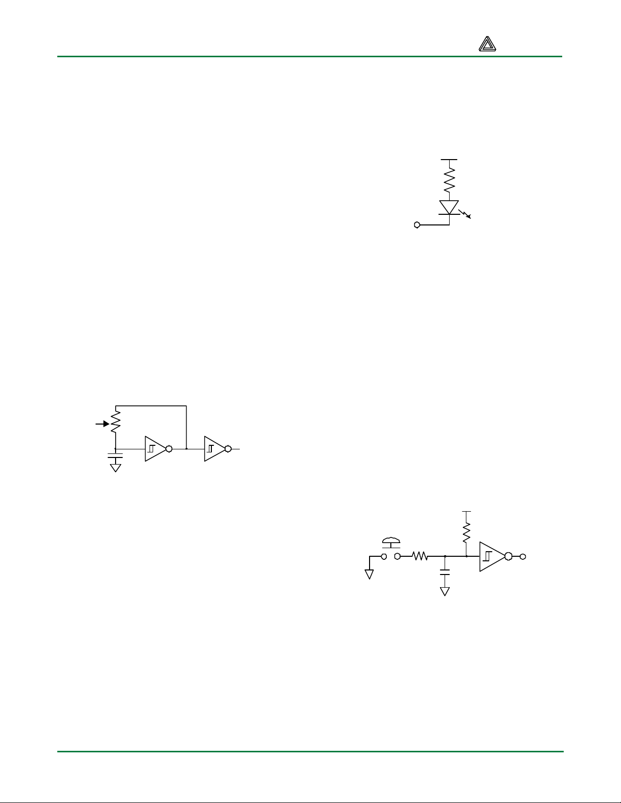
Oscillator
The Ceres board provides an user-adjustable
oscillator that can produce a clock signal in the
0.5 to 4KHz range. The oscillator circuit uses
an auto-feedback Schmidt-trigger inverter, with
a variable resistor and fixed 4.7uF capacitor in
the feedback path. The variable resistor is a
15-turn precision potentiometer that can be
adjusted from 0 to 500K ohms, providing an
RC time constant that varies by several orders
of magnitude. This clock source provides an
adequate frequency range for experiments that
run from “human time” (i.e., less than 1 Hz) to
the audio range. The oscillator output drives
the CLK0 input of the CPLD via a second
Schmidt trigger.
User
MCLK
Figure 2. Ceres Oscillator
Power Supplies
The CERES board can be powered from any
wall-plug transformer that uses a 2.1mm
center-positive jack, and that produces at least
100mA in the 5VDC to 9VDC range. The board
can also be powered from a secondary power
connector that bypasses the onboard
regulator. This 2-pin header can accommodate
a 2AA battery pack or any other power source
that outputs at least 100mA at 2.5VDC to
4.0VDC (if a supply of more than 4VDC is
applied to the secondary connector, the C-Mod
will be permanently damaged). During
operation, the board consumes less than
80mA with all LEDs and LED segments
illuminated.
Discrete LEDs
Eight individual LEDs are provided for circuit
outputs. The LED cathodes are tied to Vdd via
240-ohm resistors, and the LED cathodes are
driven directly from the C-Mod board.
240 ohms
Figure 3. LED circuit
Button Inputs
The Ceres contains four normally open
pushbuttons. Button outputs are pulled to Vdd
by a 47K resistor. When the button is pressed,
the output is connected to GND via a 4.7K
resistor. This results in a logic signal that is low
(1/10th of Vdd) only while the button is actively
pressed, and high at all other times. The
buttons are debounced with an RC filter and
Schmidt-trigger inverter as shown in the figure
below. This circuit creates a logic high signal
when the button is pressed. The debounce
circuit provides ESD protection and creates a
signal with clean edges, so the BTN# signals
can be used as clock signals if desired.
Vdd
47K
4.7K
.1uF
Figure 4. Pushbutton circuit
Slide Switches
Eight slide switches are provided for circuit
inputs. The slide switches use a 4.7Kohm
series resistor for nominal input protection.
www.digilentinc.com ® Digilent, Inc. Page 2
Page 3

Ceres Reference Manual Digilent, Inc.
Common anode
Vdd
a
SW #
4.7KΩ
GND
signal
Figure 5. Slide Switches
Seven Segment LED display
The Ceres board contains a 4-digit common
anode seven-segment LED display. The
display is multiplexed, which means only seven
cathode signals exist to drive all 28 segments
in the display. Four digit-enable signals drive
the common anodes, and these signals
determine which digit the cathode signals
illuminate.
Anodes are connected via
transistors for greater current
Vdd
AN0AN1AN2AN3
f
e
b
g
c
d
a f g e d c b
Figure 7. Common Anode Detail
This connection scheme creates a multiplexed
display, where driving the anode signals and
corresponding cathode patterns of each digit in
a repeating, continuous succession can create
the appearance of a 4-digit display. Each of the
four digits will appear bright and continuously
illuminated if the digit enable signals are driven
low once every 1 to 16ms (for a refresh
frequency of 1KHz to 60Hz). For example, in a
60Hz refresh scheme, each digit would be
illuminated for ¼ of the refresh cycle, or 4ms.
The controller must assure that the correct
cathode pattern is present when the
corresponding anode signal is driven.
Refresh period = 1ms to 16ms
Digit period = Refresh / 4
AN0
AN1
a b c d e f g dp
Cathodes are connected to
Xilinx device via 100 Ω resistors
AN2
AN3
Figure 6. Common Anode Sseg display
The seven anodes of each digit’s LEDs are
connected together into one “common anode”
circuit node. The display has four such nodes
named AN0 – AN3, and the signals that drive
these nodes serve as digit enables. Driving an
anode signal low enables the corresponding
digit. The cathodes of similar segments on all
four displays are connected into seven circuit
nodes labeled CA through CG. Driving cathode
signals low illuminates segments on any digit
whose digit enable is low.
www.digilentinc.com ® Digilent, Inc. Page 3
To illustrate the process, if AN0 is driven low
while CB and CC are driven low, then a “1” will
be displayed in digit position 0. Then, if AN1 is
driven low while CA, CB and CC are driven
low, then a “7” will be disp layed in digit position
1. If AN0 and CB, CC are driven low for 4 ms,
and then AN1 and CA, CB, CC are driven low
for 4 ms in an endless succession, the display
will show “71” in the rightmost two digits.
Digit 0
Figure 8. Sseg signal timing
Digit 1 Digit 2 Digit 3
Page 4

Ceres Reference Manual Digilent, Inc.
Digit Cathode Signals
Shown
0
1 1 0 0 1 1 1 1
2
3
4
5
6
7
8
9
Figure 9. Sseg cathode signals for digits
Expansion connector
An expansion connector labeled J1 is included
on the edge of the Ceres board to allow
designs to be expanded beyond the board. No
connector is loaded during manufacturing to
allow greater flexibility (so that wi re-wrap pins
can be loaded, or a male or female connector).
All available CPLD signals are routed to the
connector, including signals that drive onboard devices. Where feasible, on-board
devices are decoupled from the CPLD with
series resistors so that all pins may be used as
inputs or outputs by the expansion connector.
VCC and GND are also routed to the
connector so that attached devices can draw
power from the Ceres board. Table 1 shows
the signals routed to the expansion connector.
a b c d e f g
0 0 0 0 0 0 1
0 0 1 0 0 1 0
0 0 0 0 1 1 0
1 0 0 1 1 0 0
0 1 0 0 1 0 0
0 1 0 0 0 0 0
0 0 0 1 1 1 1
0 0 0 0 0 0 0
0 0 0 1 1 0 0
40 Pin DIP Socket
The Ceres Board is designed to accept any
one of several C-Mod boards. C-Mods can
easily be inserted into or removed from the 40
pin DIP socket. To add or change a C-Mod
board, power off the Ceres (disconnect the
power supply), remove an existing C-Mod
board if needed, and press the new C-Mod into
the DIP socket, ensuring that Pin 1 on the CMod is aligned with Pin 1 on the socket. Table
2 shows the signals routed to the 40-pin DIP
socket.
Table 2. Ceres board 40-DIP pinout
Pin Signal Pin Signal Pin Signal Pin Signal
1 CA 11 CG 21 GND 31 LED6
2 CB 12 AN3 22 SW6 32 LED5
3 CC 13 AN2 23 SW5 33 BTN0
4 CD 14 AN1 24 SW4 34 BTN1
5 NC 15 AN0 25 SW3 35 MCLK
6 NC 16 SW7 26 SW2 36 LED4
7 NC 17 DP 27 SW1 37 LED3
8 NC 18 BTN3 28 BTN2 38 LED2
9 CE 19 NC 29 SW0 39 LED1
10 CF 20 VCC 30 LED7 40 LED0
Table 1. Ceres expansion connector pinout
Pin Signal Pin Signal Pin Signal Pin Signal
1 GND 11 SW4 21 NC 31 LED4
2 VU 12 BTN2 22 AN1 32 CE
3 VCC 13 SW3 23 NC 33 LED3
4 NC 14 BTN1 24 AN2 34 CD
5 SW7 15 SW2 25 LED7 35 LED2
6 NC 16 BTN0 26 AN3 36 CC
7 SW6 17 SW1 27 LED6 37 LED1
8 NC 18 DP 28 CG 38 CB
9 SW5 19 SW0 29 LED5 39 LED0
10 BTN3 20 AN0 30 CF 40 CA
www.digilentinc.com ® Digilent, Inc. Page 4
 Loading...